California Code of Regulations
Title 24, Part 5
California Building
Standards Commission
Based on the 2009 Uniform Plumbing Code®
California Code of Regulations
Title 24, Part 5
California Building
Standards Commission
Based on the 2009 Uniform Plumbing Code®

EFFECTIVE DATE: January 1, 2011
(For Errata and supplements, See History Note Appendix)
Public Domain: U.S. Court of Appeals, Fifth Circuit, 99-40632
Copyright© to 2009 UPC© Held by
INTERNATIONAL ASSOCIATION OF PLUMBING AND MECHANICAL OFFICIALS
5001 East Philadelphia Street
Ontario, California 91761-2816
Copyright© to all California State Provisions
Held By
CALIFORNIA BUILDING STANDARDS COMMISSION
2525 Natomas Park Drive, Suite 130
Sacramento, CA 95833-2936
First Printing, July 1, 2010
Printed in The United States
This document is the 5th of 12 Parts of the official triennial compilation and publication of the adoptions, amendments and repeal of administrative regulations to California Code of Regulations, Title 24, also referred to as the California Building Standards Code. Part 5 is known as the California Plumbing Code and incorporates, by adoption, the 2009 edition of the Uniform Plumbing Code of the International Association of Plumbing and Mechanical Officials with the California amendments.
The California Building Standards Code is published in its entirety every three years by order of the California legislature, with supplements published in intervening years. The California legislature delegated authority to various State agencies, boards, commissions and departments to create building regulations to implement the State′s statutes. These building regulations or standards, have the same force of law, and take effect 180 days after their publication unless otherwise stipulated. The California Building Standards Code applies to occupancies in the State of California as annotated.
A city, county, or city and county may establish more restrictive building standards reasonably necessary because of local climatic, geological or topographical conditions. Findings of the local condition(s) and the adopted local building standard(s) must be filed with the California Building Standards Commission to become effective and may not be effective sooner than the effective date of this edition of California Building Standards Code. Local building standards that were adopted and applicable to previous editions of the California Building Standards Code do not apply to this edition without appropriate adoption and the required filing.
To familiarize yourself with the format of this code, it is suggested that users review the following contents:
Should you find publication (e.g., typographical) errors or inconsistencies in this code or wish to offer comments toward improving its format, please address your comments to:
California Building Standards Commission
2525 Natomas Park Drive, Suite 130
Sacramento, CA 95833-2936
Phone: (916) 263-0916
FAX: (916) 263-0959
Web Page: www.bsc.ca.gov
The 2010 California Building Standards Code (Code) was developed through the outstanding collaborative efforts of the Department of Housing and Community Development, the Division of State Architect, the Office of the State Fire Marshal, the Office of Statewide Health Planning and Development, the California Energy Commission, and the Building Standards Commission (Commission).
This collaborative effort included the assistance of the Commission’s Code Advisory Committees and many other volunteers that worked tirclessly to assist the Commission in the production of this Code.
Governor Arnold Schwarzenegger
Members of the Building Standards Commission
Acting Secretary Tom Sheehy – Chair
Isam Hasenin –-Vice-Chair
James Barthman
Craig Daley
Susan Dowty
Tony Hoffman
Christina Jamison
Stephen Jensen
Michael Paravagna
Steven Winkel
Richard Sawhill
David Walls – Executive Director
Thomas Morrison –
Deputy Executive Director
For questions on California state agency amendments; please refer to the contact list on the following page.
| California Energy Commission | |
| Energy Hotline | (800) 772-3300 or (916) 654-5106 |
| Building Efficiency Standards Appliance Efficiency Standards Compliance Manual/Forms | |
| California State Lands Commission | |
| Marine Oil Terminals | (562) 499-6317 |
| California State Library | |
| Resources and Information | (916) 654-0261 |
| Government Publication Section | (916) 654-0069 |
| Corrections Standards Authority | |
| Local Adult Jail Standards | (916) 324-1914 |
| Local Juvenile Facility Standards | (916) 324-1914 |
| Department of Consumer Affairs—Acupuncture Board | |
| Office Standards | (916) 445-3021 |
| Department of Consumer Affairs—Board of Pharmacy | |
| Pharmacy Standards | (916) 574-7900 |
| Department of Consumer Affairs—Bureau of Barbering and Cosmetology | |
| Barber and Beauty Shop and | (916) 574-7570 |
| College Standards | (800) 952-5210 |
| Department of Consumer Affairs—Bureau of Home Furnishings and Thermal Insulation | |
| Insulation Testing Standards | (916) 574-2041 |
| Department of Consumer Affairs—Structural Pest Control Board | |
| Structural Standards | (800) 737-8188 (916) 561-8708 |
| Department of Consumer Affairs—Veterinary Medical Board | |
| Veterinary Hospital Standards | (916) 263-2610 |
| Department of Food and Agriculture | |
| Meat & Poultry Packing Plant Standards | (916) 654-1447 |
| Dairy Standards | (916) 654-1447 |
| Department of Public Health | |
| Organized Camps Standards | (916) 449-5661 |
| Public Swimming Pools Standards | (916) 449-5693 |
| Asbestos Standards | (510) 620-2874 |
| Department of Housing and Community Development | |
| Residential—Hotels, Motels, Apartments Single-Family Dwellings | (916) 445-9471 |
| Permanent Structures in Mobilehome and Special Occupancy Parks | (916) 445-9471 |
| Factory-Built Housing, Manufactured Housing and Commercial Modular | (916) 445-3338 |
| Mobilehomes—Permits & Inspections Northern Region | (916) 255-2501 |
| Northern Region | (916) 255-2501 |
| Southern Region | (951) 782-4420 |
| Employee Housing Standards | (916) 445-9471 |
| Department of Water Resources | |
| Gray Water Installations Standards | (916) 651-9667 |
| Division of the State Architect—Access Compliance | |
| Access Compliance Standards | (916) 445-8100 |
| Division of the State Architect—Structural Safety | |
| Public Schools Standards | (916) 445-8100 |
| Essential Services Building Standards | (916) 445-8100 |
| Community College Standards | (916) 445-8100 |
| Division of the State Architect—State Historical Building Safety Board | |
| Alternative Building Standards | (916) 445-8100 |
| Office of Statewide Health Planning and Development | |
| Hospital Standards | (916) 440-8409 |
| Skilled Nursing Facility Standards | (916) 440-8409 |
| Clinic Standards | (916) 440-8409 |
| Permits | (916) 440-8409 |
| Office of the State Fire Marshal | |
| Code Development and Analysis | (916) 445-8200 |
| Fire Safety Standards | (916) 445-8200 |
| Fireplace Standards | (916) 445-8200 |
| Day-Care Centers Standards | (916) 445-8200 |
| Exit Standards | (916) 445-8200 |
Revised: February 24, 2010
The advantages of a uniform plumbing code adopted by various local jurisdictions has long been recognized. Disorder in the industry as a result of widely divergent plumbing practices and the use of many different, often conflicting, plumbing codes by local jurisdictions influenced the Western Plumbing Officials Association (now the International Association of Plumbing and Mechanical Officials [IAPMO]) to form a committee of plumbing inspectors, master and journeyman plumbers, and sanitary and mechanical engineers, assisted by public utility companies and the plumbing industry to create a basic plumbing document for general use. The product of this effort, the first edition of the Uniform Plumbing Code® (UPC®) was officially adopted by IAPMO in 1945. The widespread use of this code over the past five decades by jurisdictions throughout the United States and internationally is testament to its merit.
With the publication of the 2003 Edition of the Uniform Plumbing Code®, another significant milestone was reached. For the first time in the history of the United States, a plumbing code was developed through a true consensus process. The 2009 edition represents the most current approaches in the plumbing field and is the second edition developed under the ANSI consensus process. Contributions to the content of the code were made by every segment of the built industry, including such diverse interests as consumers, enforcing authorities, installers/maintainers, insurance, labor, manufacturers, research/standards/testing laboratories, special experts, and users.
The UPC is designed to provide consumers with safe and sanitary plumbing systems while, at the same time, allowing latitude for innovation and new technologies. The public at large is encouraged and invited to participate in IAPMO's open consensus code development process. This code is updated every three years. A code development timeline and other relevant information is available at IAPMO's website at www.iapmo.org.
The Uniform Plumbing Code® is dedicated to all those who, in working to achieve "the ultimate plumbing code," have unselfishly devoted their time, effort, and personal funds to create and maintain this, the finest plumbing code in existence today.
The 2009 Uniform Plumbing Code® is supported by the American Society of Sanitary Engineering (ASSE), the Mechanical Contractors Association of America (MCAA), the Plumbing-Heating-Cooling Contractors National Association (PHCC-NA), the United Association (UA), and the World Plumbing Council (WPC). The presence of these logos, while reflecting support, does not imply any ownership of the copyright to the UPC, which is held exclusively by IAPMO. Further, the logos of these associations indicates the support of IAPMO's open, consensus process being used to develop IAPMO's codes and standards.
The addresses of the organizations are as follows:
ASSE–901 Canterbury Road, Suite A• Westlake, OH 44145-7201 • (440) 835-3040
MCAA– 1385 Piccard Drive • Rockville, MD 20850 • (301) 869-5800
PHCC-NA– PO Box 6808 • Falls Church, VA 22046 • (800) 533-7694
UA – 901 Massachusetts Avenue NW • Washington, DC 20001 • (202) 628-5823
WPC – WPC Secretary • c/o Mechanical Contractors Association of Alberta
•204 2725-12 St. NE Calgary • Alberta T2E 7J2, Canada • +1-40-325-072-37
P.O. Box 2005 • Marmion, Wester Australia 6020 • +61-8-9448-0430
Code changes made to the original amalgamated code are marked in the margins as follows.
An arrow denotes a deletion
A vertical line denotes a change
| CHAPTER 1 ADMINISTRATION – DIVISION I | 3 | |
|---|---|---|
| 1.1.0 | General | 3 |
| 1.1.1 | Title | 3 |
| 1.1.2 | Purpose | 3 |
| 1.1.3 | Scope | 3 |
| 1.1.4 | Appendices | 4 |
| 1.1.5 | Referenced Codes | 4 |
| 1.1.6 | Non-Building Standards, Orders, and Regulations | 4 |
| 1.1.7 | Order of Precedence and Use | 4 |
| 1.1.8 | City, County, or City and County Amendments, Additions or Deletions | 5 |
| 1.1.9 | Effective Date of this Code | 5 |
| 1.1.10 | Availability of Codes | 5 |
| 1.1.11 | Format | 5 |
| 1.1.12 | Validity | 5 |
| 1.2.0 | Building Standards Commission | 5 |
| 1.2.2 | Alternative Materials, Design, and Methods of Construction and Equipment | 6 |
| 1.3.0 | Corrections Standards Authority | 6 |
| 1.4.0 | Department of Consumer Affairs | 6 |
| 1.5.0 | Reserved for California Energy Commission | 6 |
| 1.6.0 | Department of Food and Agriculture | 6 |
| 1.7.0 | Department of Public Health | 6 |
| 1.8.0 | Department of Housing and Community Development (HCD) | 7 |
| 1.8.1 | Purpose | 7 |
| 1.8.2 | Authority and Abbreviations | 7 |
| 1.8.3 | Local Enforcing Agency | 8 |
| 1.8.4 | Permits, Fees, Applications, and Inspections | 8 |
| 1.8.5 | Right of Entry for Enforcement | 9 |
| 1.8.6 | Local Modification by Ordinance or Regulation | 9 |
| 1.8.7 | Alternate Materials, Designs, Tests, and Methods of Construction | 10 |
| 1.8.8 | Appeals Board | 10 |
| 1.8.9 | Unsafe Buildings or Structures | 11 |
| 1.8.10 | Other Building Regulations | 11 |
| 1.9.0 | Division of the State Architect | 12 |
| 1.9.1 | Division of the State Architect–Access Compliance | 12 |
| 1.9.2 | Division of the State Architect–Structural Safety | 12 |
| 1.10.0 | Office of Statewide Health Planning and Development | 12 |
| 1.10.1 | OSHPD 1 | 12 |
| 1.10.2 | OSHPD 2 | 12 |
| 1.10.3 | OSHPD 3 | 13 |
| 1.10.4 | OSHPD 4 | 13 |
| 1.11.0 | Office of the State Fire Marshal | 13 |
| 1.11.1 | SFM-Office of the State Fire Marshal | 13 |
| 1.11.2 | Duties and Powers of the Enforcing Agency | 14 |
| 1.11.3 | Construction Documents | 16 |
| 1.11.4 | Fees | 16 |
| 1.11.5 | Inspections | 17 |
| 1.11.6 | Certificate of Occupancy | 17 |
| 1.11.7 | Temporary Structures and Uses | 17 |
| 1.11.8 | Service Utilities | 17 |
| 1.11.9 | Stop Work Order | 17 |
| 1.11.10 | Unsafe Buildings, Structures, and Equipment | 17 |
| 1.12.0 | Reserved for the State Librarian | 17 |
| 1.13.0 | Department of Water Resources (DWR) | 17 |
| 1.14.0 | Reserved for the State Lands Commission | 17 |
| DIVISION II–ADMINISTRATION | 19 | |
| 101.0 | Title, Scope, and General | 19 |
| 101.1 | Title | 19 |
| 101.2 | Purpose | 19 |
| 101.3 | Plans Required | 19 |
| 101.4 | Scope | 19 |
| 101.5 | Application to Existing Plumbing System | 19 |
| 102.0 | Organization and Enforcement | 20 |
| 102.1 | Authority Having Jurisdiction | 20 |
| 102.2 | Duties and Powers of the Authority Having Jurisdiction | 20 |
| 102.3 | Violations and Penalties | 20 |
| 103.0 | Permits and Inspections | 21 |
| 103.1 | Permits | 21 |
| 103.2 | Application for Permit | 21 |
| 103.3 | Permit Issuance | 21 |
| 103.4 | Fees | 22 |
| 103.5 | Inspections | 23 |
| 103.6 | Connection Approval | 24 |
| 103.7 | Unconstitutional | 24 |
| 103.8 | Validity | 24 |
| Table 1-1 | Plumbing Permit Fees | 25 |
| CHAPTER 2 DEFINITIONS | 29 | |
| 201.0 | General | 29 |
| 202.0 | Definition of Terms | 29 |
| CHAPTER 3 GENERAL REGULATIONS | 41 | |
| 301.0 | Materials - Standards and Alternates | 41 |
| 301.1 | Minimum Standards | 41 |
| 301.2 | Alternate Materials and Methods of Construction Equivalency | 41 |
| 301.3 | Flood Hazard Resistance | 41 |
| 301.4 | Alternative Engineered Design | 42 |
| 301.5 | One- and Two-Family Dwellings. [HCD 1 & HCD 2] | 42 |
| 302.0 | Iron Pipe Size (IPS) Pipe | 42 |
| 303.0 | Disposal of Liquid Waste | 42 |
| 304.0 | Connections to Plumbing System Required | 42 |
| 305.0 | Sewers Required | 42 |
| 306.0 | Damage to Drainage System or Public Sewer | 42 |
| 307.0 | Industrial Wastes | 43 |
| 308.0 | Location | 43 |
| 309.0 | Improper Location | 43 |
| 310.0 | Workmanship | 43 |
| 310.4 | Installation Practices | 43 |
| 311.0 | Prohibited Fittings and Practices | 43 |
| 311.8 | Screwed Fittings | 43 |
| 311.12 | [OSHPD 1, 2 & 4] Services/Systems and Utilities | 43 |
| 312.0 | Independent Systems | 43 |
| 313.0 | Protection of Piping, Materials, and Structures | 44 |
| 313.5 | Protectively Coated Pipe | 44 |
| 313.8 | Waterproofing of Openings | 44 |
| 313.10 | Sleeves | 44 |
| 313.12 | Ratproofing | 44 |
| 314.0 | Hangers and Supports | 44 |
| Table 3-1 | Hanger Rod Sizes | 45 |
| 315.0 | Trenching, Excavation, and Backfill | 45 |
| 315.3 | Open Trenches | 45 |
| 316.0 | Joints and Connections | 45 |
| 316.1 | Types of Joints | 45 |
| 316.2 | Special Joints | 46 |
| 316.3 | Flanged Fixture Connections | 46 |
| 316.4 | Prohibited Joints and Connections | 46 |
| 317.0 | Increasers and Reducers | 46 |
| 318.0 | Food-Handling Establishments | 46 |
| 319.0 | Test Gauges | 47 |
| 320.0 | [Not permitted for OSHPD 1, 2, 3 & 4] Medical Gas and Vacuum Systems | 47 |
| Table 3-2 | Hangers and Support | 48 |
| CHAPTER 4 PLUMBING FIXTURES AND FIXTURE FITTINGS | 51 | |
| 401.0 | Materials - General Requirements | 51 |
| 401.1 | Quality of Fixtures | 51 |
| 401.2 | Lead | 51 |
| 402.0 | Water-Conserving Fixtures and Fittings | 51 |
| 402.2 | Water Closets | 51 |
| 402.3 | Urinals | 51 |
| 402.4 | Metered Faucets | 52 |
| 402.5 | Emergency Safety Showers | 52 |
| 402.6 | Installation | 52 |
| 403.0 | Overflows | 52 |
| 404.0 | Strainers and Connections | 52 |
| 404.1 | Strainers | 52 |
| 404.2 | Connections | 52 |
| 405.0 | Prohibited Fixtures | 52 |
| 405.2 | Prohibited Urinals | 52 |
| 406.0 | Special Fixtures and Specialties | 52 |
| 406.1 | Water and Waste Connections | 52 |
| 406.3 | Special Use Fixtures | 53 |
| 406.4 | Zinc Alloy Components | 53 |
| 406.5 | Drinking Fountains. [HCD 1 & HCD 2] | 53 |
| 407.0 | Installation | 53 |
| 407.1 | Cleaning | 53 |
| 407.2 | Joints | 53 |
| 407.3 | Securing Fixtures | 53 |
| 407.4 | Wall-Hung Fixtures | 53 |
| 407.5 | Setting | 53 |
| 407.6 | Installations for Persons with Disabilities | 53 |
| 407.7 | Supply Fittings | 53 |
| 408.0 | Water Closets | 53 |
| 408.2 | Water Closet Seats | 53 |
| 408.3 | Securing Floor-Mounted, Back-Outlet Water Closet Bowls | 53 |
| 408.4 | Closet Rings (Closet Flanges) | 53 |
| 409.0 | Urinals | 54 |
| 410.0 | Flushing Devices for Water Closets and Urinals | 54 |
| 410.1 | Flushing Devices Required | 54 |
| 410.2 | Automatic Flushing Tanks | 54 |
| 410.3 | Flushometer Valves | 54 |
| 410.4 | Water Supply for Flush Tanks | 54 |
| 410.5 | Overflows in Flush Tanks | 54 |
| 411.0 | Floor Drains and Shower Stalls | 54 |
| 411.2 | Location of Floor Drains | 54 |
| 411.3 | Food Storage Areas | 54 |
| 411.4 | Floor Slope | 54 |
| 411.10 | Location of Valves and Heads | 56 |
| 411.11 | Water Supply Riser | 56 |
| 412.0 | Minimum Number of Required Fixtures | 56 |
| 412.1 | Fixture Count | 56 |
| 412.2 | Access to Fixtures | 56 |
| 412.3 | Separate Facilities | 56 |
| 412.4 | Fixture Requirements for Special Occupancies | 56 |
| 412.5 | Facilities in Mercantile and Business Occupancies Serving Customers | 56 |
| 412.6 | Toilet Facilities for Workers | 56 |
| 412.7 | [CA]Cosmetology | 56 |
| 412.8 | [CA]Cosmetology Establishments | 56 |
| 412.9 | [DPH] Commissaries Serving Mobile Food Preparation Units | 57 |
| 412.10 | [DPH] Employee Lavatories in Food Establishments | 57 |
| 413.0 | Fixtures and Fixture Fittings for Persons with Disabilities | 57 |
| 413.1 | Limitation of Hot Water Temperature for Public Lavatories | 57 |
| 414.0 | Bathtubs and Whirlpool Bathtubs | 57 |
| 414.5 | Limitation of Hot Water in Bathtubs and Whirlpool Bathtubs | 57 |
| 415.0 | Installation of Fixture Fittings | 57 |
| 416.0 | Bidets | 57 |
| 416.1 | Materials | 57 |
| 416.2 | Backflow Protection | 57 |
| 416.3 | Limitation of Water Temperature in Bidets | 57 |
| 417.0 | Future Fixtures | 57 |
| 418.0 | Shower and Tub-Shower Combination Control Valves | 57 |
| Table 4-1 | Minimum Plumbing Facilities | 58 |
| Table A | Occupant Load Factor | 62 |
| Table 4-2 | [OSHPD 1, 2, 3 & 4] Minimum Plumbing Facilities | 63 |
| CHAPTER 5 WATER HEATERS | 71 | |
| Part I | 71 | |
| 501.0 | General | 71 |
| 502.0 | Definitions | 71 |
| 502.1 | Appliance Categorized Vent Diameter/Area | 71 |
| 502.2 | Chimney | 71 |
| 502.3 | Chimney, Factory-Built | 71 |
| 502.4 | Chimney, Masonry | 71 |
| 502.5 | Chimney, Metal | 71 |
| 502.6 | Combustible Material | 71 |
| 502.7 | Direct-Vent Appliances | 71 |
| 502.8 | Flue Collar | 71 |
| 502.9 | Gas Vent, Type B | 71 |
| 502.10 | Gas Vent, Type L | 71 |
| 502.11 | Indirect-Fired Water Heater | 71 |
| 502.12 | Vent | 71 |
| 502.13 | Vent Connector | 71 |
| 502.14 | Venting System | 71 |
| 502.15 | Water Heater | 71 |
| 503.0 | Permits | 71 |
| Table 5-1 | First Hour Rating | 71 |
| 504.0 | Inspection | 72 |
| 504.1 | Inspection of Chimneys or Vents | 72 |
| 504.2 | Final Water Heater Inspection | 72 |
| 505.0 | Water Heater Requirements | 72 |
| 505.1 | Location | 72 |
| 505.3 | Clearance | 72 |
| 505.4 | Pressure-Limiting Devices | 72 |
| 505.5 | Temperature-Limiting Devices | 72 |
| 505.6 | Temperature, Pressure, and Vacuum Relief Devices | 72 |
| 506.0 | Oil-Burning and Other Water Heaters | 72 |
| 506.4 | Indirect-Fired Water Heaters | 72 |
| 507.0 | Air for Combustion and Ventilation | 73 |
| 507.1 | General | 73 |
| 507.2 | Indoor Combustion Air | 73 |
| 507.3 | Indoor Opening Size and Location | 74 |
| 507.4 | Outdoor Combustion Air | 74 |
| 507.5 | Combination Indoor and Outdoor Combustion Air | 74 |
| 507.6 | Engineered Installations | 74 |
| 507.7 | Mechanical Combustion Air Supply | 74 |
| 507.8 | Louvers, Grilles, and Screens | 74 |
| 507.9 | Combustion Air Ducts | 75 |
| 508.0 | Other Water Heater Installation Requirements | 75 |
| 508.2 | Protection from Seismic Damage | 75 |
| 508.5 | Relief Valve Discharge | 75 |
| 508.6 | Added or Converted Appliances | 75 |
| 508.7 | Types of Gases | 76 |
| 508.8 | Safety Shutoff Devices for Unlisted LP-Gas Appliance Used Indoors | 76 |
| 508.9 | Use of Air or Oxygen Under Pressure | 76 |
| 508.10 | Protection of Gas Appliances from Fumes or Gases Other than Products of Combustion | 76 |
| 508.11 | Process Air | 76 |
| 508.12 | Building Structural Members | 76 |
| 508.13 | Flammable Vapors | 76 |
| 508.14 | Installation in Residential Garages | 76 |
| 508.15 | Installation in Commercial Garages | 76 |
| 508.16 | Installation in Aircraft Hangars | 77 |
| 508.17 | Gas Appliance Physical Protection | 77 |
| 508.18 | Venting of Flue Gases | 77 |
| 508.19 | Extra Device or Attachment | 77 |
| 508.20 | Adequate Capacity of Piping | 77 |
| 508.21 | Avoiding Strain on Gas Piping | 77 |
| 508.22 | Gas Appliance Pressure Regulators | 77 |
| 508.23 | Venting of Gas Appliance Pressure Regulators | 77 |
| 508.24 | Bleed Lines for Diaphragm-Type Valves | 77 |
| 508.25 | Combination of Appliances | 77 |
| 508.26 | Installation Instructions | 77 |
| 508.27 | Protection of Outdoor Appliances | 78 |
| 509.0 | Appliances on Roofs | 78 |
| 509.1 | General | 78 |
| 509.2 | Installation of Appliances on Roofs | 78 |
| 509.3 | Access to Appliances on Roofs | 78 |
| 509.4 | Appliances in Attics | 78 |
| 510.0 | Venting of Appliances | 79 |
| 510.1 | General | 79 |
| 510.2 | Specification for Venting | 79 |
| 510.3 | Design and Construction | 79 |
| 510.4 | Type of Venting System to Be Used | 80 |
| 510.5 | Masonry, Metal, and Factory-Built Chimneys | 80 |
| Table 5-2 | Type of Venting System to Be Used | 82 |
| 510.6 | Gas Vents | 83 |
| 510.7 | Single-Wall Metal Pipe | 84 |
| Table 5-3 | Clearance for Connectors | 85 |
| Table 5-4 | Reduction of Clearances with Specified Forms of Protection | 86 |
| 510.8 | Through-the-Wall Vent Termination | 87 |
| 510.9 | Condensation Drain | 88 |
| 510.10 | Vent Connectors for Category I Gas Utilization Appliances | 88 |
| Table 5-5 | Minimum Thickness for Galvanized Steel Vent Connector for Low-Heat Appliances | 89 |
| Table 5-6 | Minimum Thickness for Steel Vent Connectors for Medium-Heat Appliances and Commercial and Industrial Incinerators | 89 |
| 510.11 | Vent Connectors for Category II, Category III, and Category IV Gas Utilization Appliances | 90 |
| 510.12 | Draft Hoods and Draft Controls | 90 |
| 510.13 | Manually Operated Dampers | 91 |
| 510.14 | Automatically Operated Vent Dampers | 91 |
| 510.15 | Obstructions | 91 |
| 511.0 | Sizing of Category I Venting Systems | 91 |
| 511.2 | Additional Requirements to Multiple Appliance Vent Table 5-14 through Table 5-22 | 93 |
| Table 5-7 | Vent Connector Maximum Length | 93 |
| 512.0 | Direct-Vent Appliances | 95 |
| Table 5-8 | Type B Double-Wall Gas Vent | 98 |
| Table 5-9 | Type B Double-Wall Gas Vent | 101 |
| Table 5-10 | Masonry Chimney | 103 |
| Table 5-11 | Masonry Chimney | 105 |
| Table 5-12 | Single-Wall Metal Pipe or Type B Asbestos Cement Vent | 107 |
| Table 5-13 | Exterior Masonry Chimney | 108 |
| Table 5-14 | Type B Double-Wall Vent | 109 |
| Table 5-15 | Type B Double-Wall Vent | 113 |
| Table 5-16 | Masonry Chimney | 115 |
| Table 5-17 | Masonry Chimney | 117 |
| Table 5-18 | Single-Wall Metal Pipe or Type B Asbestos Cement Vent | 119 |
| Table 5-19 | Exterior Masonry Chimney | 119 |
| Table 5-20 | Exterior Masonry Chimney | 120 |
| Table 5-21 | Exterior Masonry Chimney | 121 |
| Table 5-22 | Exterior Masonry Chimney | 122 |
| Part II | Sizing of Venting Systems Serving Appliances Equipped with Draft Hoods, Category I Appliances, and Appliances Listed for Use with Type B Vents | 123 |
| G.1 | Examples Using Single Appliance Venting Tables | 123 |
| G.2 | Examples Using Common Venting Tables | 127 |
| Table G.2.3 | Masonry Chimney Liner Dimensions with Circular Equivalents | 128 |
| J.1 | Example of Combination Indoor and Outdoor Combustion Air Opening | 130 |
| Table A.9.3.2.1 | Standard Method Volume, All Appliances | 131 |
| CHAPTER 6 WATER SUPPLY AND DISTRIBUTION | 135 | |
| 601.0 | Hot and Cold Water Required | 135 |
| 601.2 | Identification of a Potable and Non-potable Water System | 135 |
| Table 6-1 | Minimum Length of Color Field and Size of Letters | 135 |
| 601.5 | [CA] Schools of Cosmetology and Cosmetological Establishments | 135 |
| Table 6-2 | Backflow Prevention Devices, Assemblies, and Methods | 136 |
| 601.6 | [AGR] Meat and Poultry Processing Plants | 137 |
| 601.7 | [AGR] Collection Centers and Facilities | 137 |
| Table 6-3 | Minimum Airgaps for Water Distribution | 137 |
| 601.8 | [AGR] Renderers | 138 |
| 601.9 | [AGR] Horse Meat and Pet Food Establishments | 138 |
| 602.0 | Unlawful Connections | 138 |
| 603.0 | Cross-Connection Control | 138 |
| 603.1 | Approval of Devices or Assemblies | 138 |
| 603.2 | Backflow Prevention Devices, Assemblies, and Methods | 139 |
| 603.3 | General Requirements | 139 |
| 603.4 | Specific Requirements | 139 |
| 604.0 | Materials | 141 |
| Table 6-4 | Materials for Building Supply and Water Distribution Piping and Fittings | 142 |
| 604.11 | PEX | 143 |
| 604.12 | Flexible Corrugated Connectors | 143 |
| 604.13 | PEX-AL-PEX and PE-AL-PE | 143 |
| 604.14 | Water Heater Connectors | 144 |
| 605.0 | Valves | 144 |
| 606.0 | Joints and Connections | 144 |
| 606.1 | Types of Joints | 144 |
| 606.2 | Use of Joints | 145 |
| 607.0 | Gravity Supply Tanks | 145 |
| 608.0 | Water Pressure, Pressure Regulators, Pressure Relief Valves, and Vacuum Relief Valves | 145 |
| 608.1 | Inadequate Water Pressure | 145 |
| 608.2 | Excessive Water Pressure | 145 |
| 608.7 | Vacuum Relief Valves | 145 |
| 609.0 | Installation, Testing, Unions, and Location | 146 |
| 609.1 | Installation | 146 |
| 609.4 | Testing | 146 |
| 609.5 | Unions | 146 |
| 609.6 | Location | 146 |
| 609.8 | Low-Pressure Cutoff Required on Booster Pumps for Water Distribution Systems | 146 |
| 609.9 | Disinfection of Potable Water System | 146 |
| 609.10 | Water Hammer [Not Adopted by HCD] | 147 |
| 610.0 | Size of Potable Water Piping | 147 |
| 610.8 | Size of Meter and Building Supply Pipe Using Table 6-6 | 147 |
| 610.9 | Size of Branches | 148 |
| 610.10 | Sizing for Flushometer Valves | 148 |
| 610.11 | Sizing Systems for Flushometer Tanks | 148 |
| 610.12 | Sizing for Velocity | 148 |
| 610.13 | Exceptions | 148 |
| Table 6-5 | Water Supply Fixture Units (WSFU) and Minimum Fixture Branch Pipe Sizes | 149 |
| Table 6-6 | Fixture Unit Table for Determining Water Pipe and Meter Sizes | 150 |
| Table 6-7 | Flushometer Fixture Units for Water Sizing Using Table 6-5 | 151 |
| Table 6-8 | Sizing of Residential Water Softeners | 151 |
| 611.0 | Drinking Water Treatment Units | 151 |
| 611.1 | Compliance with Standard | 151 |
| 611.2 | Airgap Discharge | 151 |
| 611.3 | Connection Tubing | 151 |
| 611.4 | Sizing of Residential Softeners | 151 |
| 612.0 | [OSHPD 1, 2, 3 & 4] Domestic Hot-Water Distribution Systems for Health Facilities and Clinics | 151 |
| Table 6-9 | [OSHPD 1, 2, 3 & 4] Hot Water Use | 151 |
| 613.0 | Dialysis Water-Distribution Systems | 152 |
| 614.0 | Identification of Potable and Non-potable Water Lines | 152 |
| 614.1 | Uses Not Permitted | 152 |
| 614.4 | [OSHPD 1] Emergency Water Supply | 152 |
| CHAPTER 7 SANITARY DRAINAGE | 155 | |
| Part I Drainage Systems | 155 | |
| 701.0 | Materials | 155 |
| 701.3 | Lead | 155 |
| 701.4 | Ferrules and Bushings | 155 |
| Table 7-2(a) | Caulking Ferrules | 155 |
| Table 7-2(b) | Soldering Bushings | 155 |
| 702.0 | Fixture Unit Equivalents | 156 |
| Table 7-1 | Materials for Drain, Waste Vent Pipe, and Fittings | 156 |
| Table 7-4 | Discharge Capacity In Gallons per Minute (Liters per Second) For Intermittent Flow Only | 156 |
| 703.0 | Size of Drainage Piping | 156 |
| Table 7-3 | Drainage Fixture Unit Values (DFU) | 157 |
| 704.0 | Fixture Connections (Drainage) | 158 |
| 705.0 | Joints and Connections | 158 |
| 705.1 | Types of Joints | 158 |
| Table 7-5 | Maximum Unit Loading and Maximum Length of Drainage and Vent Piping | 158 |
| 705.2 | Use of Joints | 159 |
| 705.3 | Special Joints | 159 |
| 706.0 | Changes in Direction of Drainage Flow | 159 |
| 707.0 | Cleanouts | 159 |
| Table 7-6 | Cleanouts | 160 |
| 708.0 | Grade of Horizontal Drainage Piping | 160 |
| 709.0 | Gravity Drainage Required | 160 |
| 710.0 | Drainage of Fixtures Located Below the Next Upstream Manhole or Below the Main Sewer Level | 160 |
| 710.12 | Grinder Pump Ejector | 161 |
| 710.13 | Macerating Toilet Systems | 161 |
| 711.0 | Suds Relief | 162 |
| 712.0 | Testing | 162 |
| 712.1 | Media | 162 |
| 712.2 | Water Test | 162 |
| 712.3 | Air Test | 162 |
| Part II Building Sewers | 162 | |
| 713.0 | Sewer Required | 162 |
| 714.0 | Damage to Public Sewer or Private Sewage Disposal System | 162 |
| 715.0 | Building Sewer Materials | 163 |
| 716.0 | Markings | 163 |
| 717.0 | Size of Building Sewers | 163 |
| 717.1 | [AGR] Meat and Poultry Processing Plants | 163 |
| 718.0 | Grade, Support, and Protection of Building Sewers | 163 |
| 719.0 | Cleanouts | 163 |
| 720.0 | Sewer and Water Pipes | 164 |
| 721.0 | Location | 164 |
| Table 7-7 | Minimum Horizontal Distance Required From Building Sewer | 164 |
| Table 7-8 | Maximum/Minimum Fixture Unit Loading on Building Sewer Piping | 164 |
| 722.0 | Abandoned Sewers and Sewage Disposal Facilities | 164 |
| 723.0 | Building Sewer Test | 165 |
| 724.0 | [AGR] Meat and Poultry Processing Plant Drainage | 165 |
| 725.0 | [AGR] Collection Center and Facilities Drainage | 165 |
| 726.0 | [AGR] Drainage and Plumbing, General | 165 |
| 727.0 | [OSHPD 1] Emergency Sanitary Drainage | 165 |
| CHAPTER 8 INDIRECT WASTES | 169 | |
| 801.0 | Indirect Wastes | 169 |
| 801.1 | Airgap or Airbreak Required | 169 |
| 801.2 | Food and Beverage Handling Establishments | 169 |
| 801.3 | Bar and Fountain Sink Traps | 169 |
| 801.4 | Connections from Water Distribution System | 169 |
| 801.5 | Sterilizers | 169 |
| 801.6 | Drip or Drainage Outlets | 169 |
| 802.0 | Approvals | 169 |
| 803.0 | Indirect Waste Piping | 169 |
| 804.0 | Indirect Waste Receptors | 169 |
| 805.0 | Pressure Drainage Connections | 170 |
| 806.0 | Sterile Equipment | 170 |
| 807.0 | Appliances | 170 |
| 808.0 | Cooling Water | 170 |
| 809.0 | Drinking Fountains | 170 |
| 810.0 | Steam and Hot Water Drainage Condensers and Sumps | 170 |
| Table 8-1 | Pipe Connections in Blowoff Condensers and Sumps | 171 |
| 810.4 | Strainers | 171 |
| 811.0 | Chemical Wastes | 171 |
| 812.0 | Clear Water Wastes | 171 |
| 813.0 | Swimming Pools | 171 |
| 814.0 | Condensate Wastes and Control | 171 |
| 814.1 | Condensate Disposal | 171 |
| Table 8-2 | Minimum Condensate Pipe Size | 171 |
| 814.2 | Size | 172 |
| 814.3 | Point of Discharge | 172 |
| CHAPTER 9 VENTS | 175 | |
| 901.0 | General | 175 |
| 901.1 | Vents Required | 175 |
| 901.2 | Trap Seal Protection | 175 |
| 902.0 | Vents Not Required | 175 |
| 903.0 | Materials | 175 |
| 903.2 | Use of Copper Tubing | 175 |
| 904.0 | Size of Vents | 175 |
| 905.0 | Vent Pipe Grades and Connections | 176 |
| 906.0 | Vent Termination | 176 |
| 906.6 | Lead | 176 |
| 906.7 | Frost or Snow Closure | 176 |
| 907.0 | Vent Stacks and Relief Vents | 176 |
| 908.0 | Wet Venting | 176 |
| 908.1 | Vertical Wet Venting | 176 |
| 908.2 | Horizontal Wet Venting for Bathroom Groups | 177 |
| 909.0 | Special Venting for Island Fixtures | 177 |
| 910.0 | Combination Waste and Vent Systems | 177 |
| 911.0 | Engineered Vent System | 177 |
| 911.1 | General | 177 |
| 911.2 | Minimum Requirements | 177 |
| CHAPTER 10 TRAPS AND INTERCEPTORS | 181 | |
| 1001.0 | Traps Required | 181 |
| 1002.0 | Traps Protected by Vent Pipes | 181 |
| Table 10-1 | Horizontal Lengths of Trap Arms | 181 |
| 1003.0 | Traps - Described | 181 |
| 1004.0 | Traps - Prohibited | 182 |
| 1005.0 | Trap Seals | 182 |
| 1006.0 | Floor Drain Traps | 182 |
| 1007.0 | Trap Seal Protection | 182 |
| 1008.0 | Building Traps | 182 |
| 1009.0 | Industrial Interceptors (Clarifiers) and Separators | 182 |
| 1009.1 | When Required | 182 |
| 1009.2 | Approval | 182 |
| 1009.3 | Design | 182 |
| 1009.4 | Relief Vent | 182 |
| 1009.5 | Location | 182 |
| 1009.6 | Maintenance of Interceptors | 182 |
| 1009.7 | Discharge | 182 |
| 1010.0 | Slaughterhouses, Packing Establishments, etc | 182 |
| 1010.1 | [AGR] Meat and Poultry Processing Plants | 182 |
| 1010.2 | [AGR] Collection Centers and Facilities | 183 |
| 1010.3 | [AGR] Horse Meat and Pet Food Establishments | 183 |
| 1010.4 | [AGR] Draining and Plumbing | 183 |
| 1011.0 | Minimum Requirements for Auto Wash Racks | 183 |
| 1012.0 | Commercial and Industrial Laundries | 183 |
| 1013.0 | Bottling Establishments | 183 |
| 1014.0 | Grease Interceptors | 183 |
| 1014.2 | Hydromechanical Grease Interceptors | 184 |
| 1014.3 | Gravity Grease Interceptors | 184 |
| Table 10-2 | Hydro-mechanical Interceptor Sizing Using Gravity Flow Rates | 184 |
| 1015.0 | FOG (Fats, Oils, and Greases) Disposal System | 185 |
| 1015.1 | Purpose | 185 |
| 1015.2 | Scope | 185 |
| 1015.3 | Components, Materials, and Equipment | 185 |
| 1015.4 | Sizing Application and Installation | 185 |
| Table 10-3 | Gravity Grease Interceptor Sizing | 185 |
| 1015.5 | Performance | 185 |
| 1016.0 | Sand Interceptors | 186 |
| 1016.1 | Where Required | 186 |
| 1016.2 | Construction and Size | 186 |
| 1016.3 | Separate Use | 186 |
| 1017.0 | Oil and Flammable Liquid Interceptors | 186 |
| 1017.1 | Interceptors Required | 186 |
| 1017.2 | Design of Interceptors | 186 |
| CHAPTER 11 STORM DRAINAGE | 189 | |
| 1101.0 | General | 189 |
| 1101.1 | Where Required | 189 |
| 1101.2 | Storm Water Drainage to Sanitary Sewer Prohibited | 189 |
| 1101.3 | Material Uses | 189 |
| 1101.4 | Expansion Joints Required | 189 |
| 1101.5 | Subsoil Drains | 189 |
| 1101.6 | Building Subdrains | 189 |
| 1101.7 | Areaway Drains | 190 |
| 1101.8 | Window Areaway Drains | 190 |
| 1101.9 | Filling Stations and Motor Vehicle Washing Establishments | 190 |
| 1101.10 | Paved Areas | 190 |
| 1101.11 | Roof Drainage | 190 |
| 1101.12 | Cleanouts | 190 |
| 1102.0 | Materials | 190 |
| 1102.1 | Conductors | 190 |
| 1102.2 | Leaders | 191 |
| 1102.3 | Underground Building Storm Drains | 191 |
| 1102.4 | Building Storm Sewers | 191 |
| 1102.5 | Subsoil Drains | 191 |
| 1103.0 | Traps on Storm Drains and Leaders | 191 |
| 1103.1 | Where Required | 191 |
| 1103.2 | Where Not Required | 191 |
| 1103.3 | Trap Size | 191 |
| 1103.4 | Method of Installation of Combined Sewer | 191 |
| 1104.0 | Leaders, Conductors, and Connections | 191 |
| 1104.1 | Improper Use | 191 |
| 1104.2 | Protection of Leaders | 191 |
| 1104.3 | Combining Storm with Sanitary Drainage | 191 |
| 1105.0 | Roof Drains | 191 |
| 1105.1 | Material | 191 |
| 1105.2 | Dome or Strainer for General Use | 191 |
| 1105.3 | Strainers for Flat Decks | 191 |
| 1105.4 | Roof Drain Flashings | 191 |
| 1106.0 | Size of Leaders, Conductors, and Storm Drains | 191 |
| 1106.1 | Vertical Conductors and Leaders | 191 |
| 1106.2 | Size of Horizontal Storm Drains and Sewers | 191 |
| 1106.3 | Size of Roof Gutters | 191 |
| 1106.4 | Side Walls Draining onto a Roof | 191 |
| 1107.0 | Values for Continuous Flow | 192 |
| 1108.0 | Controlled-Flow Roof Drainage | 192 |
| 1108.1 | Application | 192 |
| Table 11-4 | Controlled-Flow Maximum Roof Water Depth | 192 |
| Table 11-5 | Distance of Scupper Bottoms Above Roof | 192 |
| 1108.2 | Setback Roofs | 192 |
| 1109.0 | Testing | 192 |
| 1109.1 | Testing Required | 192 |
| 1109.2 | Methods of Testing Storm Drainage Systems | 193 |
| Table 11-1 | Sizing Roof Drains, Leaders, and Vertical Rainwater Piping | 193 |
| Table 11-2 | Sizing of Horizontal Rainwater Piping | 194 |
| Table 11-3 | Size of Gutters | 196 |
| CHAPTER 12 FUEL PIPING | 201 | |
| 1201.0 | Scope of Gas Piping | 201 |
| 1202.0 | General | 201 |
| 1203.0 | Definitions | 201 |
| 1203.1 | Appliance Fuel Connector | 201 |
| 1203.2 | Bonding Jumper | 201 |
| 1203.3 | Fuel Gas | 201 |
| 1203.4 | Gas Piping | 201 |
| 1203.5 | Gas-Piping System | 201 |
| 1203.6 | Grounding Electrode | 201 |
| 1203.7 | Liquefied Petroleum Gas (LPG) Facilities | 201 |
| 1203.8 | Provision for Location of Point of Delivery | 202 |
| 1203.9 | Quick-Disconnect Device | 202 |
| 1203.10 | Service Piping | 202 |
| 1203.11 | Transition Gas Riser | 202 |
| 1204.0 | Inspection | 202 |
| 1205.0 | Certificate of Inspection | 202 |
| 1206.0 | Authority to Render Gas Service | 202 |
| 1207.0 | Authority to Disconnect | 202 |
| 1208.0 | Temporary Use of Gas | 202 |
| 1209.0 | Gas-Piping System Design, Materials, and Components | 203 |
| 1209.1 | Piping Plan | 203 |
| 1209.2 | Provision for Location of Point of Delivery | 203 |
| 1209.3 | Interconnections Between Gas-Piping Systems | 203 |
| 1209.4 | Sizing of Gas-Piping Systems | 203 |
| Table 12-1 | Approximate Gas Input for Typical Appliances | 203 |
| 1209.5 | Acceptable Piping Materials and Joining Methods | 204 |
| Table 12-2 | Specifications for Threading Metallic Pipe | 205 |
| 1209.6 | Gas Meters | 206 |
| 1209.7 | Gas Pressure Regulators | 207 |
| 1209.8 | Back-Pressure Protection | 208 |
| 1209.9 | Low-Pressure Protection | 208 |
| 1209.10 | Shutoff Valves | 208 |
| 1209.11 | Expansion and Flexibility | 208 |
| 1210.0 | Excess Flow Valve | 208 |
| 1211.0 | Gas Piping Installation | 208 |
| 1211.1 | Piping Underground | 208 |
| 1211.2 | Installation of Piping | 209 |
| Table 12-3 | Support of Piping | 210 |
| 1211.3 | Concealed Piping in Buildings | 210 |
| 1211.4 | Piping in Vertical Chases | 210 |
| 1211.5 | Maximum Design Operating Pressure | 210 |
| 1211.6 | Appliance Over Pressure Protection | 211 |
| 1211.7 | Gas Pipe Turns | 211 |
| 1211.8 | Drips and Sediment Traps | 211 |
| 1211.9 | Outlets | 211 |
| 1211.10 | Branch Pipe Connection | 212 |
| 1211.11 | Manual Gas Shutoff Valves | 212 |
| 1211.12 | Prohibited Devices | 212 |
| 1211.13 | Systems Containing Gas-Air Mixtures Outside the Flammable Range | 212 |
| 1211.14 | Systems Containing Flammable Gas-Air Mixtures | 212 |
| 1211.15 | Electrical Bonding and Grounding | 212 |
| 1211.16 | Electrical Circuits | 213 |
| 1211.17 | Electrical Connections | 213 |
| 1211.18 | Earthquake-Actuated Gas Shutoff Valves | 213 |
| 1212.0 | Appliance Connections to Building Piping | 213 |
| 1212.1 | Connecting Gas Appliances | 213 |
| 1212.2 | Suspended Low-Intensity Infrared Tube Heaters | 213 |
| 1212.3 | Use of Nonmetallic Gas Hose Connectors | 213 |
| 1212.4 | Connection of Portable and Mobile Industrial Gas Appliance | 214 |
| 1212.5 | Appliance Shutoff Valves and Connections | 214 |
| 1212.6 | Quick-Disconnect Devices | 214 |
| 1212.7 | Sediment Trap | 214 |
| 1212.8 | Installation of Piping | 214 |
| 1213.0 | Liquefied Petroleum Gas Facilities and Piping | 214 |
| 1214.0 | Pressure Testing and Inspection | 214 |
| 1214.1 | General | 214 |
| 1214.2 | Test Preparation | 215 |
| 1214.3 | Test Pressure | 215 |
| 1214.4 | Detection of Leaks and Defects | 215 |
| 1214.5 | Piping Systems Leak Check | 215 |
| 1214.6 | Purging | 215 |
| Table 12-5 | Length of Piping Requiring Purging with Inert Gas for Servicing or Modification | 216 |
| Table 12-6 | Length of Piping Requiring Purging with Inert Gas Before Placing in Operation | 216 |
| 1215.0 | Interconnections Between Gas Piping Systems | 216 |
| 1215.1 | Interconnections Supplying Separate Users | 216 |
| 1215.2 | Interconnections for Standby Fuels | 216 |
| 1216.0 | Required Gas Supply | 216 |
| 1217.0 | Required Gas Piping Size | 216 |
| 1217.1 | Pipe Sizing Methods | 216 |
| 1217.2 | Tables for Sizing Gas-Piping Systems | 217 |
| 1217.3 | Sizing Equations | 217 |
| Table 12-4 | Cr and Y for Natural Gas and Undiluted Propane at Standard Conditions | 217 |
| Table 12-8 | Schedule 40 Metallic Pipe | 220 |
| Table 12-9 | Schedule 40 Metallic Pipe | 221 |
| Table 12-10 | Schedule 40 Metallic Pipe | 222 |
| Table 12-11 | Schedule 40 Metallic Pipe | 223 |
| Table 12-12 | Semi-Rigid Copper Tubing | 224 |
| Table 12-13 | Semi-Rigid Copper Tubing | 225 |
| Table 12-14 | Semi-Rigid Copper Tubing | 226 |
| Table 12-15 | Semi-Rigid Copper Tubing | 227 |
| Table 12-16 | Semi-Rigid Copper Tubing | 228 |
| Table 12-17 | Semi-Rigid Copper Tubing | 229 |
| Table 12-18 | Semi-Rigid Copper Tubing | 230 |
| Table 12-19 | Corrugated Stainless Steel Tubing (CSST) | 231 |
| Table 12-20 | Corrugated Stainless Steel Tubing (CSST) | 231 |
| Table 12-21 | Corrugated Stainless Steel Tubing (CSST) | 232 |
| Table 12-22 | Corrugated Stainless Steel Tubing (CSST) | 232 |
| Table 12-23 | Corrugated Stainless Steel Tubing (CSST) | 233 |
| Table 12-24 | Polyethylene Plastic Pipe | 233 |
| Table 12-25 | Polyethylene Plastic Pipe | 234 |
| Table 12-26 | Polyethylene Plastic Pipe | 235 |
| Table 12-27 | Polyethylene Plastic Tubing | 236 |
| Table 12-28 | Polyethylene Plastic Tubing | 236 |
| Table 12-29 | Schedule 40 Metallic Pipe | 237 |
| Table 12-30 | Schedule 40 Metallic Pipe | 238 |
| Table 12-31 | Schedule 40 Metallic Pipe | 239 |
| Table 12-32 | Schedule 40 Metallic Pipe | 240 |
| Table 12-33 | Semi-Rigid Copper Tubing | 241 |
| Table 12-34 | Semi-Rigid Copper Tubing | 242 |
| Table 12-35 | Semi-Rigid Copper Tubing | 243 |
| Table 12-36 | Corrugated Stainless Steel Tubing (CSST) | 244 |
| Table 12-37 | Corrugated Stainless Steel Tubing (CSST) | 244 |
| Table 12-38 | Corrugated Stainless Steel Tubing (CSST) | 245 |
| Table 12-39 | Polyethylene Plastic Pipe | 245 |
| Table 12-40 | Polyethylene Plastic Pipe | 246 |
| Table 12-41 | Polyethylene Plastic Tubing | 247 |
| CHAPTER 13 HEALTH CARE FACILITIES AND MEDICAL GAS AND VACUUM SYSTEMS | 251 | |
| Part I Special Requirements for Health Care Facilities | 251 | |
| 1301.0 | Application | 251 |
| 1302.0 | Medical Gas and Vacuum Piping Systems-Installation Requirements | 251 |
| 1303.0 | Protrusions from Walls | 251 |
| 1304.0 | Psychiatric Patient Rooms | 251 |
| 1305.0 | Locations for Ice Storage | 251 |
| 1306.0 | Sterilizers | 251 |
| 1306.1 | General | 251 |
| 1306.2 | Indirect Waste Connections | 251 |
| 1307.0 | Vapor Vents and Stacks for Sterilizers | 251 |
| 1307.1 | General | 251 |
| 1308.0 | Aspirators | 252 |
| Part II Medical Gas and Vacuum Systems | 252 | |
| 1309.0 | Application | 252 |
| 1310.0 | Definitions | 252 |
| 1310.1 | Building Supply | 252 |
| 1310.2 | Critical Care Area | 252 |
| 1310.3 | General Care Areas | 252 |
| 1310.4 | Manifold | 252 |
| 1310.5 | Medical Air | 252 |
| 1310.6 | Medical Gas | 252 |
| 1310.7 | Medical Gas System | 252 |
| 1310.8 | Medical Vacuum System | 252 |
| 1310.9 | Nitrogen, NF (Oil-Free, Dry) (Nitrogen for Brazing and Testing) | 252 |
| 1310.10 | Patient Care Area | 252 |
| 1310.11 | Purge, Flow | 252 |
| 1310.12 | Purge, System | 252 |
| 1310.13 | SCFM | 253 |
| 1310.14 | Special Hazard Area | 253 |
| 1310.15 | Station Inlet | 253 |
| 1310.16 | Station Outlet | 253 |
| 1310.17 | Use Point | 253 |
| 1310.18 | User Outlet | 253 |
| 1310.19 | Vacuum System – Level 1 | 253 |
| 1310.20 | Valve, Isolation | 253 |
| 1310.21 | Valve, Riser | 253 |
| 1310.22 | Valve, Service | 253 |
| 1310.23 | Valve, Source | 253 |
| 1310.24 | Valve, Zone | 253 |
| 1310.25 | Waste Anesthetic Gas Disposal | 253 |
| 1311.0 | General Requirements | 253 |
| 1311.1 | Oxygen Compatibility | 253 |
| 1312.0 | Plan Review | 254 |
| 1313.0 | System Performance | 254 |
| 1313.1 | Required Operating Pressures | 254 |
| 1313.2 | Minimum Flow Rates | 254 |
| 1313.3 | Minimum Station Outlets/Inlets | 254 |
| 1314.0 | Required Pipe Sizing | 254 |
| Table 13-1 | Standard Designation Colors and Operating Pressures for Gas and Vacuum Systems | 255 |
| Table 13-2 | Minimum Flow Rates | 255 |
| Table 13-3 | Minimum Outlets/Inlets per Station | 256 |
| Table 13-4 | System Sizing - Flow Requirements for Station Inlet/Outlet | 256 |
| 1315.0 | Workmanship | 256 |
| 1316.0 | Materials | 256 |
| Table 13-5 | Outlet Rating for Vacuum Piping Systems | 257 |
| Table 13-6 | Size of Gas/Vacuum Piping | 257 |
| 1317.0 | Cleaning for Medical Gas Piping Systems | 258 |
| 1318.0 | Installation of Piping | 259 |
| Table 13-7 | Maximum Pipe Support Spacing | 260 |
| 1319.0 | Joints | 260 |
| 1320.0 | Valves - Requirements, Locations, and Labeling | 262 |
| 1320.1 | General Requirements | 262 |
| 1320.4 | Source Valve | 262 |
| 1320.5 | Main Valve | 262 |
| 1320.6 | Riser Valve | 262 |
| 1320.7 | Zone Valve | 262 |
| 1320.8 | Service Valves | 263 |
| 1321.0 | Pressure-Regulating Equipment | 263 |
| 1321.3 | Pressure Gauges | 263 |
| 1322.0 | Station Outlets/Inlets | 263 |
| 1323.0 | Labeling and Identification | 263 |
| 1324.0 | Alarms | 264 |
| 1325.0 | Medical Air System | 264 |
| 1325.6 | Medical Air Receivers | 265 |
| 1326.0 | Medical Vacuum Pump System | 265 |
| 1327.0 | Testing and Inspection | 266 |
| 1327.3 | Advance Notice | 266 |
| 1327.4 | Responsibility | 266 |
| 1327.5 | Testing | 266 |
| 1327.6 | Retesting | 266 |
| 1327.7 | Initial Pressure Test – Piped Gas Systems | 266 |
| 1327.8 | Cross-Connection Test – Piped Gas Systems | 266 |
| 1327.9 | Final Testing Standing Pressure Test – Piped Gas Systems | 267 |
| 1327.10 | Initial Pressure Test – Piped Vacuum Systems | 267 |
| 1327.11 | Standing Pressure Test – Piped Vacuum Systems | 267 |
| 1327.12 | Corrections | 268 |
| 1327.13 | Approval | 268 |
| 1327.14 | Covering or Use | 268 |
| 1327.15 | Uncovering | 268 |
| 1328.0 | System Certification | 268 |
| CHAPTER 14 REFERENCED STANDARDS | 271 | |
| Table 14-1 | Standards for Materials, Equipment, Joints, and Connections | 271 |
| Abbreviations in Table 14-1 | 291 | |
| CHAPTER 15 FIRESTOP PROTECTION | 295 | |
| 1501.0 | General Requirements | 295 |
| 1501.1 | Applicability | 295 |
| 1502.0 | Plans and Specifications | 295 |
| 1503.0 | Installation | 295 |
| 1504.0 | Definitions | 295 |
| 1504.1 | Penetration Firestop System | 295 |
| 1504.2 | F Rating | 295 |
| 1504.3 | T Rating | 295 |
| 1505.0 | Combustible Piping Installations | 295 |
| 1505.5 | Insulation and Coverings | 295 |
| 1505.6 | Sleeves | 295 |
| 1506.0 | Non-Combustible Piping Installations | 295 |
| 1506.6 | Sleeves | 296 |
| 1506.7 | Insulation and Coverings | 296 |
| 1507.0 | Required Inspection | 296 |
| 1507.1 | General | 296 |
| CHAPTER 16 RESERVED | 297 | |
| CHAPTER 16A NON-POTABLE WATER REUSE SYSTEMS | 301 | |
| Part I [HCD 1] | 301 | |
| 1601A.0 | Graywater Systems - General | 301 |
| 1602A.0 | Definitions | 301 |
| 1603A.0 | Permit | 302 |
| 1603A.1 | System Requirements | 302 |
| Table 1603A.1.4 | Construction Permit Requirements | 303 |
| 1604A.0 | Drawings and Specifications | 303 |
| 1604A.1 | Groundwater Depth | 303 |
| 1605A.0 | Inspection and Testing | 303 |
| 1606A.0 | Procedure for Estimating Graywater Discharge | 303 |
| 1607A.0 | Required Area of Irrigation or Disposal Fields | 303 |
| 1608A.0 | Determination of Maximum Absorption Capacity | 304 |
| 1609A.0 | Tank Construction | 304 |
| 1610A.0 | Graywater Systems | 304 |
| 1610A.1 | Pipe Materials | 304 |
| 1610A.2 | Identification | 304 |
| 1610A.3 | Valves | 304 |
| 1611A.0 | Irrigation, Disposal Field, and Mulch Basin Construction | 304 |
| 1611A.1 | Mulch Basin | 304 |
| 1611A.2 | Irrigation Field | 304 |
| 1611A.3 | Disposal Field | 305 |
| 1612A.0 | Special Provisions | 305 |
| 1612A.1 | Indoor Use of Treated Graywater | 305 |
| Table 16A-1 | Location of Graywater System | 306 |
| Table 16A-2 | Design Criteria of Six Typical Soils | 306 |
| Table 16A-3 | Subsurface Drip Design Criteria of Six Typical Soils | 306 |
| Part II [DWR] | 307 | |
| 1613A.0 | Recycled Water Systems – General | 307 |
| 1614A.0 | Definitions | 307 |
| 1615A.0 | Permit | 307 |
| 1616A.0 | Drawings and Specifications | 307 |
| 1617A.0 | Pipe Material/Pipe Identification | 307 |
| 1617A.1 | Pipe Materials | 307 |
| 1617A.2 | Color and Information | 307 |
| 1618A.0 | Installation | 307 |
| 1619A.0 | Signs | 307 |
| 1620A.0 | Inspection and Testing | 308 |
| 1621A.0 | Sizing | 309 |
| APPENDICES TABLE OF CONTENTS | 311 | |
| Appendix A | Recommended Rules for Sizing the Water Supply System | 315 |
| Appendix B | Explanatory Notes on Combination Waste and Vent Systems | 333 |
| Appendix D | Sizing Storm Water Drainage Systems | 337 |
| Appendix G | Graywater Systems | 347 |
| Appendix I | Installation Standards Table of Content | 359 |
| Appendix K | Private Sewage Disposal Systems | 457 |
| Appendix L | Alternate Plumbing Systems | 469 |
| USEFUL TABLES | 475 | |
| INDEX | 483 | |
| HISTORY NOTE APPENDIX | 504 | |
To distinguish between model code language and incorporated California amendments, including exclusive California standards, California amendments will appear in italics. Symbols indicate the status of code changes as follows:
[SFM] This symbol following a section leader identifies which state agency(s) have amended a section of model code. For a complete listing of state agencies, refer to the Application Sections within Chapter 1, Division I.
This symbol in the margin indicates that a change has been made to a California amendment.
This symbol in the margin indicates deletion of California language.

The Documents Listed are Not by this Reference Adopted by The State of California.
IAPMO provides a variety of other products which are useful for inspectors, building officials, architects, engineers, manufacturers, contractors, plumbers, and apprentices.
IAPMO Headquarters Directory
5001 East Philadelphia Street, Ontario, California 91761-2816
Publication Order Desk Phone: 800-85-IAPMO
Publication Toll Free Fax: 877-85-CODES
E-mail: publications@iapmo.org
Website: www.iapmo.org
Free Code Question Answers & Analysis: 800-201-0335
Uniform Plumbing Code – 2009 Edition:
The Uniform Plumbing Code is the most widely adopted plumbing code in the world. The 2009 edition contains complete "turnkey" requirements for the installation and maintenance of plumbing systems, all in one easy to use book.
Uniform Plumbing Code Illustrated Training Manual:
The UPC Illustrated Training Manual is an excellent reference for anyone involved in the plumbing industry. It contains an extensive definitions section and several hundred comprehensive technical diagrams and illustrations. It serves as a textbook, and it also is useful as a valuable tool for explaining the intent and use of the Code.
Uniform Plumbing Code Study Guide:
This book is the perfect complement to the UPC Illustrated Training Manual. Alone, it constitutes a complete self-study course for learning the UPC. It has hundreds of questions, general practice exams, and plumbing math, pipe sizing exercises and fitting identification. A big help in getting you ready for a certification exam!
Uniform Plumbing Code Answer & Analysis Manual:
This increasing popular manual is the result of ongoing work by IAPMO's Answers & Analysis Committee. It contains hundreds of questions and answers that encompass three editions of the UPC. Many of these questions arise in the daily administration of the code.
Cumulative Analysis of Uniform Plumbing Code Changes:
An excellent reference for learning and understanding plumbing code changes and identifies code changes between editions. It is a useful tool for preparing code change proposals.
Uniform Mechanical Code – 2009 Edition:
The Uniform Mechanical Code contains complete requirements for the installation and maintenance of heating, ventilating, cooking and refrigeration systems.
Uniform Mechanical Code Illustrated Training Manual:
Contains technical diagrams and illustrations that demonstrate the intent and use of the UMC. A great reference for everyone involved in Mechanical HVACR design and installation.
Uniform Mechanical Code Study Guide:
The Study Guide is a complete self-study course for learning the UMC. A big help in getting ready for a certification exam! This book is the perfect complement to the UMC Illustrated Training Manual.
Uniform Mechanical Code Answer & Analysis Manual:
This increasing popular manual is the result of ongoing work by IAPMO's Answers & Analysis Committee. It contains hundreds of questions and answers that encompass three editions of the UMC. Many of these questions arise in the daily administration of the code.
Cumulative Analysis of Uniform Mechanical Code Changes:
The UMC Cumulative Analysis is a very useful tool in targeting the latest changes between editions of the code. It is an excellent guide for anyone proposing a UMC change.
Uniform Swimming Pool, Spa, and Hot Tub Code – 2009 Edition:
The Uniform Swimming Pool, Spa and Hot Tub Code contains complete and current requirements for the erection, installation, alteration, repair, relocation, replacement, addition to and use or maintenance of these systems.
Uniform Solar Energy Code – 2009 Edition:
The Uniform Solar Energy Code is a unique document that provides a complete set of regulations and guidelines that cover both plumbing and mechanical systems in one "turnkey" package. The code is ideal for use by inspectors, jurisdictions and the installation industry.
Drain Waste and Vent Calculator:
A slide-rule style calculator provides quick and simple access to the fixture unit and sizing tables of Chapter 7 of the UPC.
Water Sizing Calculator:
Sizing water systems becomes a much simpler task with the use of this handy slide-rule style calculator.
Natural Gas Pipe Sizing Calculator:
This Natural Gas Pipe Sizing Calculator is presented in an easy to use and read slide-rule format. Designed for systems with a supply pressure of six to eight inches of water column, all pipe capacities are given in cubic feet per hour.
Trailer Standards:
IAPMO has developed a number of standards for specialty products used in manufactured homes and recreational vehicles. These standards are available individually, or they may be purchased as a set.
Directory of Listed Plumbing Products:
The IAPMO Listing Program was primarily created to benefit the building and plumbing officials that the products installed meet the appropriate standards and code. For a product to continue to be listed, unannounced inspections of the manufacturing facilities verify continued compliance. This directory contains information on several thousand IAPMO-listed plumbing products and is updated annually.
Education and Training Seminars:
IAPMO specializes in conducting training and education, including fulfilling continuing education requirements, on the UPC and UMC as well as all of the most commonly utilized codes in the Construction Trades. Special seminars on industry or code subjects are expeditiously created and delivered upon request. Please call to obtain the seminar schedule or to arrange for a custom special seminar.
Backflow Prevention Institute – IAPMO
The IAPMO Backflow Prevention Institute provides professional education and training for the control of hazards to our water supply and is dedicated to water-system safety worldwide. The Institute provides training in backflow prevention and cross-connection control. This program includes backflow preventers, testers, repairers, cross-connection control surveyors, program administrators and fire-sprinkler backflow preventer testers. Each of these courses provides compliance certification to American Society of Sanitary Engineering (ASSE) Series 5000 Professional Qualification Standards.
Backflow Prevention Reference Manual:
This unique 300-page manual contains full-color illustrations and sections relating to real-world installations, backflow prevention, testing cross-connection control, repair and inspections. The manual is an excellent textbook and a reference the inspectors in every jurisdiction should have access too. It is also an important resource for system designers, urban planners and utility companies – professionals on both sides of the water meter.
Drinking Water & Backflow Prevention Magazine:
A monthly subscription to Drinking Water & Backflow Prevention Magazine provides current and valuable information regarding this critical public health topic. Subjects range from actual incident reporting, application of the newest technology, and general interest articles including fire systems, irrigation systems, and security as well as installation, inspection and repair tips.
Backflow Prevention Tech-Wheel:
Find quick answers to your backflow preventer questions! The Backflow Tech-Wheel contains a wealth of information in a graphic, quick reference format. One side delivers solutions to device application questions; the other a troubleshooting guides offering solutions to backflow problems.
ANSI Z 124 Standards:
These standards are written to specifically address a variety of plastic plumbing fixtures and components. They are available individually, or may be grouped for quantity discounts.
IAPMO Installation Standards:
IAPMO standards committees have formulated installation standards for a wide variety of commonly used plumbing materials and systems. The IAPMO installation standards are included after the text of the Uniform Plumbing Code, or can be purchased separately.
Material and Property Standards:
IAPMO does not generally develop material and property standards, but when a need exists the Association will take a leadership role by filling the void. They are available, are subject to amendments and are withdrawn when recognized consensus standards are formulated.
OFFICIAL Magazine:
IAPMO's bimonthly publication features informative articles related to plumbing and Mechanical HVACR installations, award winning general interest features, technical columns and industry updates. Subscriptions are available and all IAPMO members receive a free copy of every issue!
Membership in IAPMO:
IAPMO membership is open to all interested persons. Membership categories include Student, Individual, Senior, Organizational and Governmental. Member benefits include discounted prices on IAPMO publications, a subscription to Official magazine, and numerous educational and training opportunities.
Mailing Address: 5001 East Philadelphia Street, Ontario, California 91761-2816
Main Number: 909-472-4100 • Publication Orders: 800-85-IAPMO •Publication Fax: 877-85-CODES
Website: www.iapmo.org •Office Hours: Monday – Friday, 8am – 5pm Pacific Time
Format of the Matrix Adoption Tables
The matrix adoption tables, which follow, show the user which state agencies have adopted and/or amended given sections of model code for applications within their respective authorities. See Chapter 1, See Section 1.2.0 through 1.14.0, for building application and enforcement responsibilities.
The side headings identify the scope of the state agencies’ adoption as follows:
Adopt the Entire UPC Chapter without state amendments
If there is an "X" under a particular state agency's acronym on this row, this means that particular state agency has adopted the entire model code chapter without any state amendments.
Example:
CALIFORNIA PLUMBING CODE - MATRIX ADOPTION TABLE
CHAPTER 1 - ADMINISTRATION
Adopt the Entire UPC chapter as amended (amendments listed below)
If there is an "X" under a particular state agency's acronym on this row, it means that particular state agency has adopted the entire model code chapter, with state amendments.
Each state-amended section that the agency has added to that particular chapter is listed. There will be an "X" in the column, by that particular section, under the agency′s acronym, as well as an "X" by each section that the agency has adopted.
Example:
Adopts only those section which are listed below:
CALIFORNIA PLUMBING CODE - MATRIX ADOPTION TABLE
CHAPTER 1 - ADMINISTRATION
If there is an "X" under a particular state agency′s acronym on this row, it means that particular state agency is adopting only specific model code or state-amended sections within this chapter. There will be an "X" in the column under the agency′s acronym, as well as an "X" by each section that the agency has adopted.
Example:
CALIFORNIA PLUMBING CODE - MATRIX ADOPTION TABLE
CHAPTER 1 - ADMINISTRATION
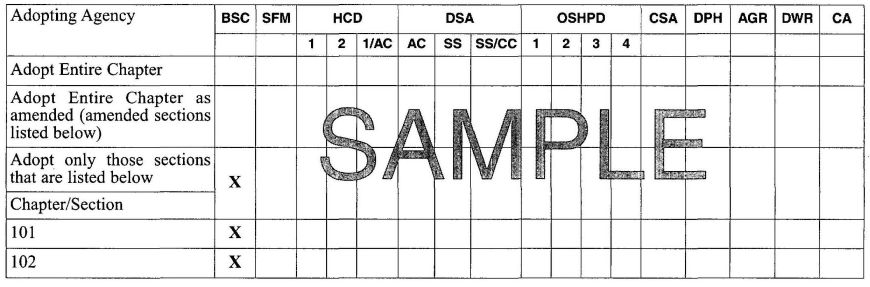
| Legend of Abbreviations of Adopting State Agencies | |
|---|---|
| BSC | California Building Standards Commission |
| SFM | Office of the State Fire Marshal |
| HCD | Department of Housing and Community Development |
| DSA-AC | Division of the State Architect - Access Compliance |
| DSA-SS | Division of the State Architect - Structural Safety |
| DSA-SS/CC | Division of the State Architect - Community Colleges |
| OSHPD | Office of Statewide Health Planning and Development |
| CSA | Corrections Standards Authority |
| DPH | Department of Public Health |
| AGR | Department of Food and Agriculture |
| DWR | Department of Water Resources |
| CA | Department of Consumer Affairs |
| Adopting Agency | BSC | SFM | HCD | DSA | OSHPD | CSA | DPH | AGR | DWR | CA | |||||||
|---|---|---|---|---|---|---|---|---|---|---|---|---|---|---|---|---|---|
| 1 | 2 | 1/AC | AC | SS | SS/CC | 1 | 2 | 3 | 4 | ||||||||
| Adopt Entire Chapter | |||||||||||||||||
| Adopt Entire Chapter as amended (amended sections listed below) | |||||||||||||||||
| Adopt only those sections that are listed below | X | X | X | X | X | X | X | X | X | X | X | X | X | X | X | X | X |
| Chapter/Section | |||||||||||||||||
| Division 1— California Administration | |||||||||||||||||
| 1.1.0-1.1.7 | X | X | X | X | X | X | X | X | X | X | X | X | X | X | X | X | |
| 1.1.8 | X | X | X | X | X | X | X | X | X | X | X | X | X | X | |||
| 1.1.9-1.1.11 | X | X | X | X | X | X | X | X | X | X | X | X | X | X | X | X | |
| 1.1.12 | X | X | X | X | X | X | X | X | X | X | X | X | X | X | |||
| 1.2.0 | X | ||||||||||||||||
| 1.3.0 | X | ||||||||||||||||
| 1.4.0 | X | ||||||||||||||||
| 1.6.0 | X | ||||||||||||||||
| 1.7.0 | X | ||||||||||||||||
| 1.8.0 | X | X | X | ||||||||||||||
| 1.9.0 | X | ||||||||||||||||
| 1.9.1 | X | ||||||||||||||||
| 1.9.2.1 | X | ||||||||||||||||
| 1.9.2.2 | X | ||||||||||||||||
| 1.10.1 | X | ||||||||||||||||
| 1.10.2 | X | ||||||||||||||||
| 1.10.3 | X | ||||||||||||||||
| 1.10.4 | X | ||||||||||||||||
| 1.11.0 | X | ||||||||||||||||
| 1.13.0 | X | ||||||||||||||||
| Division II - Administration | |||||||||||||||||
| 101.0 - 103.1.1 | X | X | X | X | |||||||||||||
| 103.1.2 and subsections | X | X | X | X | X | X | |||||||||||
| 103.1.1 - 103.8 | X | X | X | X | |||||||||||||
1.1.0 General.
1.1.1 Title. These regulations shall be known as the California Plumbing Code, may be cited as such and will be referred to herein as “this code.” The California Plumbing Code is Part 5 of twelve parts of the official compilation and publication of the adoption, amendment, and repeal of plumbing regulations to the California Code of Regulations, Title 24, also referred to as the California Building Standards Code. This part incorporates by adoption the 2009 Uniform Plumbing Code of the International Association of Plumbing and Mechanical Officials with necessary California amendments.
1.1.2 Purpose. The purpose of this code is to establish the minimum requirements to safeguard the public health, safety and general welfare through structural strength, means of egress facilities, stability, access to persons with disabilities, sanitation, adequate lighting and ventilation, and energy conservation; safety to life and property from fire and other hazards attributed to the built environment; and to provide safety to fire fighters and emergency responders during emergency operations.
1.1.3 Scope. The provisions of this code shall apply to the construction, alteration, movement, enlargement, replacement, repair, equipment, use and occupancy, location, maintenance, removal, and demolition of every building or structure or any appurtenances connected or attached to such buildings or structures throughout the State of California.
1.1.3.1 Non-State-Regulated Buildings, Structures, and Applications. Except as modified by local ordinance pursuant to Section 1.1.8, the following standards in the California Code of Regulations, Title 24, Parts 2, 2.5, 3, 4, 5, 6, 9, 10 and 11 shall apply to all occupancies and applications not regulated by a state agency.
1.1.3.2 State-Regulated Buildings, Structures, and Applications. The model code, state amendments to the model code, and/or state amendments where there are no relevant model code provisions shall apply to the following buildings, structures, and applications regulated by state agencies as referenced in the Matrix Adoption Tables and as specified in Section 1.2.0 through 1.14.0, except where modified by local ordinance pursuant to Section 1.1.8. When adopted by a state agency, the provisions of this code shall be enforced by the appropriate enforcing agency, but only to the extent of authority granted to such agency by the state Legislature.
Note: See Preface to distinguish the model code provisions from the California provisions.
1.1.4 Appendices. Provisions contained in the appendices of this code shall not apply unless specifically adopted by a state agency or adopted by a local enforcing agency in compliance with Health and Safety Code Section 18901 et seq. for Building Standards Law, and Health and Safety Code Section 17950 for State Housing Law and Health and Safety Code Section 13869.7 for Fire Protection Districts. See Section 1.1.8 of this code.
1.1.5 Referenced Codes. The codes, standards and publications adopted and set forth in this code, including other codes, standards and publications referred to therein are, by title and date of publication, hereby adopted as standard reference documents of this code. When this code does not specifically cover any subject related to building design and construction, recognized architectural or engineering practices shall be employed. The National Fire Codes, standards, and the Fire Protection Handbook of the National Fire Protection Association are permitted to be used as authoritative guides in determining recognized fire prevention engineering practices.
1.1.6 Non-Building Standards, Orders, and Regulations. Requirements contained in the Uniform Plumbing Code, or in any other referenced standard, code or document, which are not building standards as defined in Health and Safety Code Section 18909 shall not be construed as part of the provisions of this code. For nonbuilding standards, orders, and regulations, see other titles of the California Code of Regulations.
1.1.7 Order of Precedence and Use.
1.1.7.1 Differences. In the event of any differences between these building standards and the standard reference documents, the text of these building standards shall govern.
1.1.7.2 Specific Provisions. Where a specific provision varies from a general provision, the specific provision shall apply.
1.1.7.3 Conflicts. When the requirements of this code conflict with the requirements of any other part of the California Building Standards Code, Title 24, the most restrictive requirements shall prevail.
1.1.8 City, County, or City and County Amendments, Additions or Deletions. The provisions of this code do not limit the authority of city, county, or city and county governments to establish more restrictive and reasonably necessary differences to the provisions contained in this code pursuant to complying with Section 1.1.8.1. The effective date of amendments, additions, or deletions to this code by city, county, or city and county field pursuant to Section 1.1.8.1 shall be the date filed. However, in no case shall the amendments, additions or deletions to this code be effective any sooner than the effective date of this code.
Local modifications shall comply with Health and Safety Code Section 18941.5 for Building Standards Law, Health and Safety Code Section 17958 for State Housing Law or Health and Safety Code Section 13869.7 for Fire Protection Districts.
1.1.8.1. Findings and Filings.
Exception: Hazardous building ordinances and programs mitigating unreinforced masonry buildings.
1.1.9 Effective Date of this Code. Only those standards approved by the California Building Standards Commission that are effective at the time an application for building permit is submitted shall apply to the plans and specifications for, and to the construction performed under, that permit. For the effective dates of the provisions contained in this code, see the History Note page of this code.
1.1.10 Availability of Codes. At least one complete copy each of Titles 8, 19, 20, 24, and 25 with all revisions shall be maintained in the office of the building official responsible for the administration and enforcement of this code. Each state department concerned and each city, county, or city and county shall have an up-to-date copy of the code available for public inspection. See Health and Safety Code Section 18942 (d)(1) and (2).
1.1.11 Format. This part fundamentally adopts the Uniform Plumbing Code by reference on a chapter-by-chapter basis. Such adoption is reflected in the Matrix Adoption Table of each chapter of this part. When the Matrix Adoption Tables make no reference to a specific chapter of the Uniform Plumbing Code, such chapter of the Uniform Plumbing Code is not adopted as a portion of this code.
1.1.12 Validity. If any chapter, section, subsection, sentence, clause or phrase of this code is for any reason held to be unconstitutional, contrary to statute, exceeding the authority of the state as stipulated by statutes or otherwise inoperative, such decision shall not affect the validity of the remaining portion of this code.
1.2.0 Building Standards Commission.
1.2.1 Specific scope of application of the agency responsible for enforcement, the enforcement agency, and the specific authority to adopt and enforce such provisions of this code, unless otherwise stated.
1.2.2 Alternative Materials, Design, and Methods of Construction and Equipment.
The provisions of this code are not intended to prevent the installation of any material or to prohibit any design or method of construction not specifically prescribed by this code, provided that any such alternative has been approved. An alternative material, design or method of construction shall be approved where the building official finds that the proposed design is satisfactory and complies with the intent of the provisions of this code, and that the material, method or work offered is, for the purpose intended, at least the equivalent of that prescribed in this code in quality, strength, effectiveness, fire resistance, durability, and safety.
1.2.2.1 Research Reports. Supporting data, where necessary to assist in the approval of materials or assemblies not specifically provided for in this code, shall consist of valid research reports from approved sources.
1.2.2.2 Tests. Whenever there is insufficient evidence of compliance with the provisions of this code, or evidence that a material or method does not conform to the requirements of this code, or in order to substantiate claims for alternative materials or methods, the building official shall have the authority to require tests as evidence of compliance to be made at no expense to the jurisdiction. Test methods shall be as specified in this code or by other recognzied test standards. In the absence of recognized and accepted test methods, the buildings official shall approve the testing procedures. Tests shall be performed by an approved agency. Reports of such tests shall be retained by the building official for the period required for retention of public records.
1.3.0 Corrections Standards Authority.
1.3.1 Specific scope of application of the agency responsible for enforcement, the enforcement agency, and the specific authority to adopt and enforce such provisions of this code, unless otherwise stated.
Application – Local detention facilities.
Enforcing Agency – Corrections Standards Authority.
Authority Cited – Penal Code Section 6030; Welfare and Institutions Code Sections 210 and 885.
References – Penal Code Section 6030; Welfare and Institutions Code Sections 210 and 885.
1.4.0 Department of Consumer Affairs.
1.4.1 Specific scope of application of the agency responsible for enforcement, the enforcement agency, and the specific authority to adopt and enforce such provisions of this code, unless otherwise stated.
Board of Barbering and Cosmetology.
Application – Any establishment or mobile unit where barbering, cosmetology, or electrolysis is being performed.
Enforcing Agency – State or local agency specified by applicable provisions of law.
Authority Cited – Business and Professions Code Section 7312.
References – Business and Professions Code Sections 7303, 7303.1, 7312, and 7313.
1.5.0 Reserved for California Energy Commission.
1.6.0 Department of Food and Agriculture.
1.6.1 Specific scope of application of the agency responsible for enforcement, the enforcement agency, and the specific authority to adopt and enforce such provisions of this code, unless otherwise stated.
Application – Dairies and places of meat and poultry inspection.
Enforcing Agency – Department of Food and Agriculture.
Authority Cited – Food and Agricultural Code Sections 18735, 18960, 19384, 33481, and 33731.
References – Food and Agricultural Code Sections 18735, 18960, 19384, 33481, and 33731.
1.7.0 Department of Public Health.
1.7.1 Specific scope of application of the agency responsible for enforcement, the enforcement agency, and the specific authority to adopt and enforce such provisions of this code, unless otherwise stated.
Department of Public Health.
Application – Commissaries serving mobile food preparation units, food establishments, and organized camps.
Enforcing Agency – Department of Health Services and local health agency.
Authority Cited – Health and Safety Code Sections 18897.2, 110065, 113710, and 131200.
References – Health and Safety Code Sections 18897.2, 18897.4, 18897.7, 110065, 113705, 113710, and 131200.
1.8.0 Department of Housing and Community Development. [HCD]
1.8.1 Purpose. The purpose of this code is to establish minimum requirements to protect the health, safety, and general welfare of the occupants and the public by governing the erection, construction, reconstruction, enlargement, conversion, alteration, repair, moving, removal, demolition, sanitation, ventilation, and maintenance or use of plumbing equipment or systems.
1.8.2 Authority and Abbreviations.
1.8.2.1 General. The Department of Housing and Community Development is authorized by law to promulgate and adopt building standards and regulations for several types of building applications. These applications are grouped and identified by abbreviation in the Matrix Adoption Tables to show which model code sections and amendments are applicable to each application. The applications under the authority of the Department of Housing and Community Development are listed in Sections 1.8.2.1.1 through 1.8.2.1.3.
1.8.2.1.1 Housing Construction.
Application – Hotels, motels, lodging houses, apartment houses, dwellings, dormitories, condominiums, shelters for homeless persons, congregate residences, employee housing, factory-built housing, and other types of dwellings containing sleeping accommodations with or without common toilet or cooking facilities including accessory buildings, facilities, and uses thereto. Sections of this code which pertain to applications listed in this section are identified in the Matrix Adoption Table using the abbreviation ”HCD 1“.
Enforcing Agency – Local building department or the Department of Housing and Community Development.
Authority Cited – Health and Safety Code Sections 17040, 17050, 17920.9, 17921, 17921.3, 17921.6, 17921.10, 17922, 17922.6, 17922.12, 17927, 17928, 17959.6, 18300, 18552, 18554, 18620, 18630, 18640, 18670, 18690, 18691, 18865, 18871.3, 18871.4, 18873, 18873.1, 18873.2, 18873.3, 18873.4, 18873.5, 18938.3, 18944.11, and 19990: and Government Code Section 12955.1.
References – Health and Safety Code Sections 17000 through 17062.5, 17910 through 17995.5, 18200 through 18700, 18860 through 18874, and 19960 through 19997; and Government Code Sections 12955.1 and 12955.1.1.
1.8.2.1.2 Housing Accessibility.
Application – Covered multifamily dwellings as defined in Chapter 11A of the California Code of Regulations, Title 24, Part 2, also known as the California Building Code (CBC) including but not limited to lodging houses, dormitories, timeshares, condominiums, shelters, for homeless persons, congregate residences, apartment houses, dwellings employee housing, factory-built housing, and other types of dwellings containing sleeping accommodations with or without common toilet or cooking facilities.
Sections of this code identified in the Matrix Adoption Table by the abbreviation “HCD 1-AC” require specific accommodations for “PERSONS WITH DISABILITIES” as defined in Chapter 11A of the CBC. The application of such provisions shall be in conjunction with other requirements of this code and apply only to newly constructed “COVERED MULTIFAMILY DWELLING” as defined in Chapter 11A of the CBC. “HCD 1-AC” applications include, but are not limited to, the following:
HCD 1-AC building standards generally do not apply to public use areas or public accommodations such as hotels and motels. Public use areas, public accommodations and housing which is publicly funded as defined in Chapter 2 of the CBC are subject to the Division of the State Architect (DSA-AC) and are referenced in Section 1.9.1.
Enforcing Agency– Local building department or the Department of Housing and Community Development.
Authority Cited – Health and Safety Code Sections 17040, 17050, 17920.9, 17921, 17921.3, 17921.6, 17921.10, 17922, 17922.6, 17922.12, 17927, 17928, 17959.6, 18300, 18552, 18554, 18620, 18630, 18640, 18670, 18690, 18691, 18865, 18871.3, 18871.4, 18873, 18873.1, 18873.2, 18873.3, 18873.4, 18873.5, 18938.3, 18944.11, and 19990; and Government Code Section 12955.1.
References – Health and Safety Code Sections 17000 through 17062.5, 17910 through 17995.5, 18200 through 18700, 18860 through 18874, and 19960 through 19997; and Government Code Sections 12955.1 and 12955.1.1.
1.8.2.1.3 Permanent Buildings in Mobilehome Parks and Special Occupancy Parks.
Application– Permanent buildings, and permanent accessory buildings or structures, constructed within mobilehome parks and special occupancy
Parks that are under the control and ownership of the park operator. Sections of this code which pertain to applications listed in this section are identified in the Matrix Adoption Table using the abbreviation “HCD 2”
Enforcing Agency– Local building department or other local agency responsible for the enforcement of Health and Safety Code Division 13, Part 2.1, commencing with Section 18200 for mobilehome parks and Health and Safety Code, Division 13, Part 2.3, commencing with Section 18860 for special occupancy parks; or the Department of Housing and Community Development.
Authority Cited – Health and Safety Code Sections 17040, 17050, 17920.9, 17921, 17921.3, 17921.6, 17921.10, 17922, 17922.6, 17922.12, 17927, 17928, 17959.6, 18300, 18552, 18554, 18620, 18630, 18640, 18670, 18690, 18691, 18865, 18871.3, 18871.4, 18873, 18873.1, 18873.2, 18873.3, 18873.4, 18873.5, 18938.3, 18944.11 and 19990; and Government Code Section 12955.1.
References – Health and Safety Code Sections 17000 through 17062.5, 17910 through 17995.5, 18200 through 18700, 18860 through 18874, and 19960 through 19997; and Government Code Sections 12955.1 and 12955.1.1.
1.8.3 Local Enforcing Agency.
1.8.3.1 Duties and Powers. The building department of every city, county or city and county shall enforce all the provisions of law, this code, and the other rules and regulations promulgated by the Department of Housing and Community Development pertaining to the installation, erection, construction, reconstruction, movement, enlargement, conversion, alteration, repair, removal, demolition, or arrangement of apartment houses, hotels, motels, lodging houses and dwellings, including accessory buildings, facilities, and uses thereto.
The provisions regulating the erection and construction of dwellings and appurtenant structures shall not apply to existing structures as to which construction is commenced or approved prior to the effective date of these regulations. Requirements relating to use, maintenance and occupancy shall apply to all dwellings and appurtenant structures approved for construction or constructed before or after the effective date of this code.
For additional information regarding the use and occupancy of existing buildings and appurtenant structures, see California Code of Regulations, Title 25, Division 1, Chapter 1, Subchapter 1, commencing with Section 1.
1.8.3.2 Laws, Rules, and Regulations. Other than the building standards contained in this code, and notwith-standing other provisions of law, the statutory authority and location of the laws, rules, and regulations to be enforced by local enforcing agencies are listed by statute in Sections 1.8.3.2.1 through 1.8.3.2.5 below:
1.8.3.2.1 State Housing Law. Refer to the State Housing Law, California Health and Safety Code, Division 13, Part 1.5, commencing with Section 17910 and California Code of Regulations, Title 25, Division 1, Chapter 1, Subchapter 1, commencing with Section 1, for the erection, construction, reconstruction, movement, enlargement, conversion, alteration, repair, removal, demolition, or arrangement of apartment houses, hotels, motels, lodging houses and dwellings, including accessory buildings, facilities, and uses thereto.
1.8.3.2.2 Mobilehome Parks Act. Refer to the mobilehome Parks Act, California Health and Safety Code, Division 13, Part 2.1, commencing with Section 18200 and California Code of Regulations, Title 25, Division 1, Chapter 2, commencing with Section 1000 for mobilehome park administrative and enforcement authority, permits, plans, fees, violations, inspections, and penalties both within and outside mobilehome parks.
Exception: Mobilehome parks where the Department of Housing and Community Development is the enforcing agency.
1.8.3.2.3 Special Occupancy Parks Act. Refer to the Special Occupancy Parks Act, California Health and Safety Code, Division 13, Part 2.3, commencing with Section 18860 and California Code of Regulations, Title 25, Division 1, Chapter 2.2, commencing with Section 2000 for special occupancy park administrative and enforcement authority, permits, fees, violations, inspections, and penalties both within and outside of special occupancy parks.
Exception: Special occupancy parks where the Department of Housing and Community Development is the enforcing agency.
1.8.3.2.4 Employee Housing Act. Refer to the Employee Housing Act, California Health and Safety Code, Division 13, Part 1, commencing with Section 17000 and California Code of Regulations, Title 25, Division 1, Chapter 1, Subchapter 3, commencing with Section 600 for employee housing administrative and enforcement authority, permits, fees, violations, inspections, and penalties.
1.8.3.2.5 Factory-Built Housing Law. Refer to the Factory-Built Housing Law, California Health and Safety Code, Division 13, Part 6 commencing with Section 19960 and California Code of Regulations, Title 25, Division 1, Chapter 3, Subchapter 1, commencing with Section 3000 for factory-built housing administrative and enforcement authority, permits, fees, violations, inspections, and penalties.
1.8.4 Permits, Fees, Applications, and Inspections.
1.8.4.1 Permits. A written construction permit shall be obtained from the enforcing agency prior to the erection, construction, reconstruction, installation, relocation, or alteration of any plumbing system.
Exceptions:
- Work exempt form permits as specified in Chapter 1, Administration, Division II, Sections 103.1.2.1 and 103.1.2.2 of this code.8
- Changes, alterations, or repairs of a minor nature not affecting structural features, egress, sanitation, safety, or accessibility as determined by the enforcing agency.
Exemptions from permit requirements shall not be deemed to grant authorization for any work to be done in any manner in violation of other provisions of law or this code.
1.8.4.2 Fees. Subject to other provisions of law, the governing body of any city, county, or city and county may prescribe fees to defray the cost of enforcement of rules and regulations promulgated by the Department of Housing and Community Development. The amount of the fees shall not exceed the amount reasonably necessary to administer or process permits, certificates, forms, or other documents, or to defray the costs of enforcement. For additional information, see State Housing Law, Health and Safety Code, Division 13, Part 1.5, Section 17951 and California Code of Regulations, Title 25, Division 1, Chapter 1, Subchapter 1, Article 3, commencing with Section 6.
1.8.4.3 Plan Review and Time Limitations. Subject to other provisions of law, provisions related to plan checking, prohibition of excessive delays, and contracting with or employment of private parties to perform plan checking are set forth in the State Housing Law, Health and Safety Code Section 17960.1, and for employee housing, in Health and Safety Code Section 17021.
1.8.4.3.1 Retention of Plans. The building department of every city, county, or city and county shall maintain an official copy, microfilm, or electronic or other type of photographic copy of the plans of every building, during the life to the building, for which the department issued a building permit.
Exceptions:
- Single or multiple dwellings not more than two stories and basement in height.
- Garages and other structures appurtenant to buildings listed in Exception 1.
- Farm or ranch buildings appurtenant to buildings listed in Exception 1.
- Any one-story building where the span between bearing walls does not exceed 25 feet (7620 mm), except a steel frame or concrete building.
All plans for common interest developments as defined in Section 1351 of the California Civil Code shall be retained. For additional information regarding plan retention and reproduction of plans by an enforcing agency, see Health and Safety Code Sections 19850 through 19852.
1.8.4.4 Inspections. Construction or work for which a permit is required shall be subject to inspection by the building official and such construction or work shall remain accessible and exposed for inspection purposes until approved. Approval as a result of an inspection shall not be construed to be an approval of a violation of the provisions of the code or other regulations of the Department of Housing and Community Development.
1.8.5 Right of Entry for Enforcement.
1.8.5.1 General. Subject to other provisions of law, officers and agents of the enforcing agency may enter and inspect public and private properties to secure compliance with the rules and regulations promulgated by the Department of Housing and Community Development. For limitations and additional information regarding enforcement, see the following:
1.8.6 Local Modification by Ordinance or Regulation.
1.8.6.1 General. Subject to other provisions of law, a city, county or city and county may make changes to the provisions adopted by the Department of Housing and Community Development. If any city, county, or city and county does not amend, add, or repeal by local ordinances or regulations the provisions published in this code or other regulations promulgated by the Department of Housing and Community Development, those provisions shall be applicable and shall become effective 180 days after publication by the California Building Standards Commission. Amendments, additions, and deletions to this code adopted by a city, county or city and county pursuant to California Health and Safety Code Sections 17958.5, 17958.7, and 18941.5, together with all applicable portions of this code, shall also become effective 180 days after publications of the California Building Standard Code by the California Building Standards Commission.
1.8.6.2 Findings, Fillings, and Rejections of Local Modifications. Prior to making any modifications or establishing more restrictive building standards, the governing body shall make express findings and filings, as required by California Health and Safety Code Section 17958.7, showing that such modifications are reasonably necessary due to local climatic, geological, or topographical conditions. No modification shall become effective or operative unless the following requirements are met:
1.8.7 Alternate Materials, Designs, Tests, and Methods of Construction.
1.8.7.1 General. The provisions of this code as adopted by the Department of Housing and Community Development are not intended to prevent the use of any alternate material, appliance, installation, device, arrangement, design, or method of construction not specifically prescribed by this code. Consideration and approval of alternates shall comply with Section 1.8.7.2 for local building departments and Section 1.8.7.3 for the Department of Housing and Community Development.
1.8.7.2 Local Building Departments. The building department of any city, county, or city and county may approve alternates for use in the erection, construction, reconstruction, movement, enlargement, conversion, alteration, repair, removal, demolition, or arrangement of an apartment house, hotel, motel, lodging house, or dwelling or an accessory structure, except for the following:
1.8.7.2.1 Approval of Alternates. The consideration and approval of alternates by a local building department shall comply with the following procedures and limitations:
1.8.7.3 Department of Housing and Community Development. The Department of Housing and Community Development may approve alternates for use in the erection, construction, reconstruction, movement, enlargement, conversion, alteration, repair, removal, or demolition of an apartment house, hotel, motel, loading house, dwelling, or an accessory thereto. The consideration and approval of alternates shall comply with the following:
1.8.8 Appeals Board.
1.8.8.1 General. Every city, county, or city and county shall establish a local appeals board and a housing appeals board. The local appeals board and housing appeals board shall each be comprised of at least five voting members who shall serve at the pleasure of the city, county or city and county. Appointees shall not be employees of the jurisdiction and shall be qualified and specifically knowledgeable in the California Building Standards Codes and applicable local ordinances.
1.8.8.2 Definitions. The following terms shall for the purposes of this section have the meaning shown.
Housing Appeals Board. The board or agency of a city, county or city and county which is authorized by the governing body of the city, county, or city and county to hear appeals regarding the requirements of the city, county, or city and county relating to the use, maintenance, and change or occupancy of buildings and structures, including requirements governing alteration, additions, repair, demolition, and moving. In any area in which there is not such board or agency, “housing appeals board” means the local appeals board having jurisdiction over the area.
Local Appeals Board. The board or agency of a city, county, or city and county which is authorized by the governing body of the city, county, or city and county to hear appeals regarding the building requirements of the city, county, or city and county. In any area in which there is no such board or agency, “local appeals board” means the governing body of the city, county, or city and county having jurisdiction over the area.
1.8.8.3 Appeals. Except as otherwise provided by law, any person, from, or corporation adversely affected by a decision, order, or determination by a city, county, or city and county relating to the application of building standards published in the California Building Standards Code, or any other applicable rule or regulation adopted by the Department of Housing and Community Development, or any lawfully enacted ordinance by a city, county, or city and county, may appeal the issue for resolution to the local appeals board or housing appeals board as appropriate.
The local appeals board shall hear appeals relating to new building construction and the housing appeals board shall hear appeals relating to existing buildings.
1.8.9 Unsafe Buildings or Structures.
1.8.9.1 Authority to Enforce. Subject to other provisions of law, the administration, enforcement, actions, proceedings, abatement, violations, and penalties for unsafe buildings and structures are contained in the following statutes and regulations:
1.8.9.2 Actions and Proceedings. Subject to other provisions of law, punishments, penalties, and fines for violations of building standards are contained in the following statutes and regulations:
1.8.10 Other Building Regulations.
1.8.10.1 Existing Structures. Notwithstanding other provisions of law, the replacement, retention, and extension of original materials and the use of original methods of construction for any existing building or accessory structure, or portions thereof, shall be permitted. For additional information, see California Health and Safety Code Sections 17912 and 17958.8.
1.8.10.2 Moved Structures. Subject to the requirements of California Health and Safety Code Sections 17922.3 and 17958.9, local ordinances or regulations relating to a moved residential or accessory structure shall, after July 1, 1978, permit the retention of existing materials and methods of construction so long as the structure does not become or continue to be a substandard building.
Note:
Authority Cited – Health and Safety Code Sections 17040, 17050, 17920.9, 17921, 17921.3, 17921.6, 17921.10, 17922, 17922.6, 17922.12, 17927, 17928, 17959.6, 18300, 18552, 18554, 18620, 18630, 18640, 18670, 18690, 18691, 18865, 18871.3, 18871.4, 18873, 18873.1, 18873.2, 18873.3, 18873.4, 18873.5, 18938.3, 18944.11, and 19990; and Government Code Section 12955.1.
References – Health and Safety Code Sections 17000 through 17062.5, 17910 through 17995.5, 18200 through 18700, 18860 through 18874, and 19960 through 19997; and Government Code Sections 12955.1 and 12955.1.1.
1.9.0 Division of the State Architect.
1.9.1 Division of the State Architect–Access Compliance.
Note: For applications listed in Section 1.9.1 of the California Building Code, regulated by the Division of the State Architect – Access Compliance see California Code of Regulations, Title 24, Part 2 (California Building Code), Chapter 1 (Division 1 California Administration) under authority cited by Government Code Section 4450 and in reference cited by Government Code Section 4450 through 4461, 12955.1, and Health and Safety Code Sections 18949.1, 19952 through 19959.
1.9.2 Division of the State Architect — Structural Safety.
1.9.2.1 DSA-SS (Division of the State Architect — Structural Safety).
Application — Public elementary and secondary schools, community college buildings, and state-owned or state-leased essential services buildings.
Enforcing Agency — (Division of the State Architect — Structural Safety) (DSA - SS).
The Division of the State Architect has been delegated the responsibility and authority by the Department of General Services to review and approve the design and observe the construction of public elementary and secondary schools, community colleges, and state-owned or state-leased essential services buildings.
Authority Cited — Education Code Section 17310 and 81142, and Health and Safety Code Section 16022.
References — Education Code Sections 17280 through 17317 and 81130 through 81147, and Health and Safety Code Sections 16000 through 16023.
1.9.2.2. DSA-SS/CC (Division of the State Architect — Structural Safety/Community Colleges).
Application — Community Colleges.
The Division of the State Architect has been delegated the authority by the Department of General Services to promulgate alternate building standards for application to community colleges, which a community college may elect to use in lieu of standards promulgated by DSA-SS in accordance with Section 1.9.2.1. Refer to Title 24, Part 2, Section 1.9.2.2.
Enforcing Agency — Division of the State Architect — Structural Safety/Community Colleges (DSA-SS/CC).
The Division of the State Architect has been delegated the authority by the Department of General Services to review and approve the design and oversee construction of community colleges electing to use the alternative building standards as provided in this section.
Authority Cited — Education Code Section 81053.
References — Education Code Sections 81052, 81053, and 81130 through 81147.
1.10.0 Office of Statewide Health Planning and Development.
1.10.1 OSHPD 1. Specific scope of application of the agency responsible for enforcement, enforcement agency, specific authority to adopt and enforce such provisions of this code, unless otherwise stated.
OSHPD 1
Application – General acute-care hospitals and acute psychiatric hospitals, excluding distinct part units or distinct part freestanding buildings providing skilled nursing or intermediate-care services. For Structural Regulations: Skilled nursing facilities and/or intermediate-care facilities except those skilled nursing facilities and intermediate care facilities of single story, Type V, wood or light steel-frame construction.
Enforcing Agency – Office of Statewide Health planning and Development (OSHPD). The office shall enforce the Division of the State Architect access compliance regulations and the regulations of the Office of the State Fire Marshal for the above stated facility types.
1.10.1.1 Applicable Administrative Standards.
1.10.1.2 Applicable Building Standards. California Building Standards Code, Title 24, Parts 2,3,4,5,9,10, and 11.
Authority Cited – Health and Safety Code Sections 127010, 127015, 1275, and 129850.
References – Health and Safety Code Sections 19958, 127010, 127015, 129680, 1275, and 129675 through 130070.
1.10.2 OSHPD 2. Specific scope of application of the agency responsible for enforcement, enforcement agency, specific authority to adopt and enforce such provisions of this code, unless otherwise stated.
OSHPD 2
Application – Skilled nursing facilities and intermediate-care facilities, including distinct part skilled nursing and intermediate-care services on a general acute-care or acute psychiatric hospital license, provided either in a rate unit or a freestanding building. For Structural Regulations: Single-story, Type V skilled nursing facility and/or intermediate-care facilities utilizing wood or light steel-frame construction.
Enforcing Agency – Office of Statewide Health Planning and Development (OSHPD). The office shall also enforce the Division of the State Architect access compliance regulations and the regulations of the Office of the State Fire Marshal for the above stated facility type.
1.10.2.1 Applicable Administrative Standards:
1.10.2.2 Applicable Building Standards. California Building Standards Code, Title 24, Parts 2,3,4,5,9,10, and 11.
Authority Cited – Health and Safety Code Sections 127010, 127015, 1275, and 129850.
References – Health and Safety Code Sections 127010, 127015, 1275, and 129680.
1.10.3 OSHPD 3. Specific scope of application of the agency responsible for enforcement, enforcement agency, specific authority to adopt and enforce such provisions of this code, unless otherwise stated.
OSHPD 3
Application – Licensed clinics and any freestanding building under a hospital license where outpatient clinical services are provided.
Enforcing Agency – Local building department.
1.10.3.1 Applicable Administrative Standards.
1.10.3.2 Applicable Building Standards. California Building Standards Code, Title 24, Parts 2,3,4,5,9,10, and 11.
Authority Cited – Health and Safety Code Sections 127010, 127015, and 1226.
References– Health and Safety Code Sections 127010, 127015, 129885, and 1226, Government Code Section 54350, and State Constitution Article 11, Section 7.
1.10.4 OSHPD 4. Specific scope of application of the agency responsible for enforcement, enforcement agency, specific authority to adopt and enforce such provisions of this code, unless otherwise stated.
OSHPD 4
Application – Correctional Treatment Centers.
Enforcing Agency – Office of Statewide Health Planning and Development (OSHPD). The office shall also enforce the Division of the State Architect access compliance regulations and the regulations of the Office of the State Fire Marshal for the above stated facility types.
1.10.4.1 Applicable Administrative Standards.
1.10.4.2 Applicable Building Standards. California Building Standards Code, Title 24, Parts 2, 3, 4, 5, 9, 10 and 11.
Authority Cited – Health and Safety Code Sections 127010, 127015, and 129790.
References – Health and Safety Code Sections 127010, 127015, 1275, and 129675 through 130070.
1.11.0 Office of the State Fire Marshal.
1.11.1 SFM-Office of the State Fire Marshal. Specific scope of application of the agency responsible for enforcement, the enforcement agency and the specific authority to adopt and enforce such provisions of this code, unless otherwise stated.
Application:
Institutional, Educational, or any Similar Occupancy. Any building or structure used or intended for use as an asylum, jail, mental hospital, hospital, sanitarium, home for the aged, children’s nursery, children’s home, school, or any similar occupancy of any capacity.
Authority Cited – Health and Safety Code Section 13143.
Reference – Health and Safety Code Section 13143.
Assembly or Similar Place of Assemblage. Any theater, dancehall, skating rink, auditorium, assembly hall, meeting hall, nightclub, fair building, or similar place of assemblage where 50 or more persons may gather together in a building, room or structure for the purpose of amusement, entertainment, instruction, deliberation, worship, drinking or dining, awaiting transportation, or education.
Authority Cited – Health and Safety Code Section 13143.
Reference – Health and Safety Code Section 13143.
Small Family Day-Care Homes.
Authority Cited – Health and Safety Code Sections 1597.45, 1597.54, 13143, and 17921.
Reference – Health and Safety Code Section 13143.
Large Family Day-Care Homes.
Authority Cited – Health and Safety Code Section 1597.46, 1597.54, and 17921.
Reference – Health and Safety Code Section 13143.
Residential Facilities and Residential Facilities for the Elderly.
Authority Cited – Health and Safety Code Section 13133.
Reference – Health and Safety Code Section 13143.
Any State Institution or Other State– Owned or State–Occupied Building.
Authority Cited – Health and Safety Code Section 13108.
Reference – Health and Safety Code Section 13143.
High-Rise Structures.
Authority Cited – Health and Safety Code Section 13211.
Reference – Health and Safety Code Section 13143.
Motion Picture Production Studios.
Authority Cited – Health and Safety Code Section 13143.1
Reference – Health and Safety Code Section 13143.
Organized Camps.
Authority Cited – Health and Safety Code Section 18897.3
Reference – Health and Safety Code Section 13143.
Residential.
All hotels, motels, lodging houses, apartment houses and dwellings, including congregate residences and buildings and structures accessory thereto. Multiple-story structures existing on January 1, 1975, let for human habitation, including and limited to, hotels, motels, apartment houses, less than 75 feet(22 860 mm) above the lowest floor level having building access, wherein rooms used for sleeping are let above the ground floor.
Authority Cited – Health and Safety Code Sections 13143.2 and 17921.
Reference – Health and Safety Code Section 13143.
Residential Care Facilities.
Certified family-care homes, out-of-home placement facilities, halfway houses, drug and/or alcohol rehabilitation facilities, and any building or structure used or intended for use as a home or institution for the housing of any person of any age when such person is referred to or placed within such home or institution for protective social care and supervision services by any governmental agency.
Authority Cited – Health and Safety Code Section 13143.6.
Reference – Health and Safety Code Section 13143.
Tents, Awnings, or Other Fabric Enclosures Used in Connection with Any Occupancy.
Authority Cited– Health and Safety Code Section 13116.
Reference – Health and Safety Code Section 13143.
Fire Alarm Devices, Equipment, and Systems in Connection with Any Occupancy.
Authority Cited – Health and Safety Code Section 13114.
Reference – Health and Safety Code Section 13143.
Hazardous Materials.
Authority Cited – Health and Safety Code Section 13143.9.
Reference – Health and Safety Code Section 13143.
Flammable and Combustible Liquids.
Authority Cited – Health and Safety Code Section 13143.6
Reference – Health and Safety Code Section 13143.
Public School Automatic Fire Detection, Alarm, and Sprinkler Systems.
Authority Cited – Health and Safety Code Section 13143 and California Education Code Article 7.5, Sections 17074.50, 17074.52, and 17074.54.
References – Government Code Section 11152.5, Health and Safety Code Section 13143 and California Education Code Chapter 12.5, Leroy F. Greene School Facilities Act of 1998, Article 1.
Wildland-Urban Interface Fire Area.
Authority Cited – Health and Safety Code Sections 13143, 13108.5(a), and 18949.2(b) and (c); and Government Code Section 51189.
References – Health and Safety Code Sections 13143, Government Code Sections 51176, 51177, 51178, and 51179; and Public Resources Code Sections 4201 through 4204.
1.11.2 Duties and Powers of the Enforcing Agency.
1.11.2.1 Enforcement.
1.11.2.1.1 The responsibility for enforcement of building standards adopted by the State Fire Marshal and published in the California Building Standards Code relating to fire and panic safety and other regulations of the State Fire Marshal shall except as provided in Section 1.11.2.1.2 be as follows:
1.11.2.1.2 Pursuant to Health and Safety Code Section 13108, and except as otherwise provided in this section, building standards adopted by the State Fire Marshal published in the California Building Standards Code relating to fire and panic safety shall be enforced by the State Fire Marshal in all state –owned buildings, state –occupied buildings, and state owned buildings, state –occupied buildings, and state institutions throughout the state. Upon the written request of the chief fire official of any city, county, or fire-protection district, the State Fire Marshal may authorize such chief fire official and his or her authorized representatives, in their geographical area of responsibility, to make fire-prevention inspections of state-owned or state-occupied buildings, other than state institutions, for the purpose of enforcing the regulations relating to fire and panic safety adopted by the State Fire Marshal pursuant to this section and building standards relating to fire and panic safety published in the California Building Standards Code. Authorization from the State Fire Marshall shall be limited to those fire departments or fire districts which maintain a fire-prevention bureau staffed by paid personnel.
Pursuant to Health and Safety Code Section 13108, any requirement or order made by any chief fire official who is authorized by the State Fire Marshal to make fire-prevention inspections of state –owned or state-occupied buildings, other than state institutions, may be appealed to the State Fire Marshal. The State Fire Marshal shall, upon receiving an appeal and subject to the provisions of Chapter 5 (commencing with Section 18945) of Part 2.5 of Division 13 of the Health and Safety Code, determine if the requirement or order made is reasonably consistent with the fire and panic safety regulations adopted by the State Fire Marshal and building standards relating to fire and panic safety published in the California Building Code.
Any person may request a code interpretation from the State Fire Marshal relative to the intent of any regulation or provision adopted by the State Fire Marshal. When the request relates to a specific project, occupancy or building, the State Fire Marshal shall review the issue with the appropriate local enforcing agency prior to rendering such code interpretation.
1.11.2.1.3 Pursuant to Health and Safety Code Section 13112, any persons who violates any order, rule or regulation of the State Fire Marshal is guilty of a misdemeanor punishable by a fine of not less than $100.00 or more than $500.00, or by imprisonment for not less than six months, or by both. A person is guilty of a separation offense each day during which he or she commits, continues, or permits a violation of any provision of, or any order, rule or regulation of, the State Fire Marshall as contained in this code.
Any inspection authority who, in the exercise of his or her authority as a deputy State Fire Marshal, causes and legal complaints to be filed or any arrest to be made shall notify the State Fire Marshal immediately following such action.
1.11.2.2 Right of Entry. The fire chief of any city, county, or fire-protection district, or such person’s authorized representative, may enter any state institution or any other state-owned or state-occupied building for the purpose of preparing a fire –suppression preplanning program or for the purpose of investigating any fire in a state-occupied building.
The State Fire Marshal, his or her deputies or salaried assistants, the chief of any city or county fire department or fire-protection district and his or her authorized representatives may enter any building or premises not used for dwelling purposes at any reasonable hour for the purpose of enforcing this chapter. The owner, lessee, manager, or operator of any such building or premises shall permit the State Fire Marshal, his or her deputies or salaried assistants and the chief of any city or county fire department or fire-protection district and his or her authorized representatives to enter and inspect them at the time and for the purpose stated in this section.
1.11.2.3 More Restrictive Fire and Panic Safety Building Standards.
1.11.2.3.1 Any fire-protection district organized pursuant to Health and Safety Code Part 2.7 (commencing with Section 13800) of Division 12 may adopt building standards relating to fire and panic safety that are more stringent than those building standards adopted by the State Fire Marshal and contained in the California Building Standards Code. For these purposes, the district board shall be deemed a legislative body and the district shall be deemed a local agency. Any changes or modifications that are more stringent than the requirements published in the California Building Standards Code relating to fire and panic safety shall be subject to Section 1.1.8.1.
1.11.2.3.2 Any fire protection district that proposes to adopt an ordinance pursuant to this section shall, not less than 30 days prior to noticing a proposed ordinance for public hearing, provide a copy of that ordinance, together with the adopted findings made pursuant to Section 1.11.2.3.1, to the city, county, or city and county where the ordinance will apply. The city, county, or city and county may provide the district with written comments, which shall become part of the fire-protection district’s public hearing record.
1.11.2.3.3 The fire-protection district shall transmit the adopted ordinance to the city, county, or city and county where the ordinance will apply. The legislative body of the city, county, or city and county may ratify, modify or deny an adopted ordinance and transmit its determination to the district within 15 days of the determination. Any modification or denial of an adopted ordinance shall include a written statement
describing the reasons for any modifications or denial. No ordinance adopted by the district shall be effective until ratification by the city, county, or city and county where the ordinance will apply. Upon ratification of an adopted ordinance, the city, county, or city and county shall file a copy of the findings of the district, and any findings of the city, county, or city and county together with the adopted ordinance expressly marked and identified to which each finding refers, in accordance with Section 1.1.8.1(3).
1.11.2.4 Request for Alternate Means of Protection. Requests for approval to use an alternative material, assembly or materials, equipment, method of construction, method of installation of equipment, or means of protection shall be made in writing to the enforcing agency by the owner or the owner's authorized representative and shall be accompanied by a full statement of the conditions. Sufficient evidence or proof shall be submitted to substantiate any claim that may be made regarding its conformance. The enforcing agency may require tests and the submission of a test report from an approved testing organization as set forth in Title 19, California Code of Regulation, to substantiate the equivalency of the proposed alternative means of protection.
When a request for alternate means of protection involves hazardous materials, the Authority Having Jurisdiction may consider implementation of the findings and recommendations identified in a Risk Management Plan (RMP) developed in accordance with Title 19, Division 2, Chapter 4.5, Article 3.
Approval of a request for use of an alternative material, assembly of materials, equipment, method of construction, method of installation of equipment, or means of protection made pursuant to these provisions shall be limited to the particular case covered by request and shall not be construed as establishing any precedent for any future request.
1.11.2.5 Appeals. When a request for an alternate means of protection has been denied by the enforcing agency, the applicant may file a written appeal to the State Fire Marshal for consideration of the applicant's proposal. In considering such appeal, the State Fire Marshal may seek the advice of the State Board of Fire Services. The State Fire Marshal shall, after considering all of the facts presented, including any recommendations of the State Board of Fire Services, determine if the proposal is for the purposes intended, at least equivalent to that specified in these regulations in quality, strength, effectiveness, fire resistance, durability, and safety, and shall transmit such findings and any recommendations to the applicant and to the enforcing agency.
1.11.3 Construction Documents. In addition to the provisions of this Section, see Title 24, Part 2, California Building Code, Appendix Chapter 1, Section 106 for additional requirements.
1.11.3.1 Public Schools. Plans and specifications for the construction, alteration or addition to any building owned, leased or rented by any public school district shall be submitted to the Division of the State Architect.
1.11.3.2 Movable Walls and Partitions. Plans or diagrams shall be submitted to the enforcing agency for approval before the installation of, or rearrangement of, any movable wall or partition in any occupancy. Approval shall be granted only if there is no increase in the fire hazard.
1.11.3.3 New Construction High-Rise Buildings.
1.11.3.4 Existing High-Rise Buildings.
1.11.3.5 Retention of Plans. Refer to Building Standards Law, Health and Safety Code Sections 19850 and 19851, for permanent retention of plans.
1.11.4 Fees
1.11.4.1 Other Fees. Pursuant to Health and Safety Code Section 13146.2, a city, county, or district which inspects a hotel, motel, lodging house, or apartment house may
charge and collect a fee for the inspection from the owner of the structure in an amount, as determined by the city, county, or district, sufficient to pay its costs of that inspection.
1.11.4.2 Large Family Day Care. Pursuant to Health and Safety Code Section 1597.46, Large Family Day Care Homes, the local government shall process any required permit as economically as possible, and fees charged for review shall not exceed the costs of the review and permit process.
1.11.4.3 High-Rise. Pursuant to Health and Safety Code Section 13217, High-Rise Structure Inspection: Fees and Costs, a local agency which inspects a high-rise structure pursuant to Health and Safety Code Section 13217 may charge and collect a fee for the inspection from the owner of the high-rise structure in an amount, as determined by the local agency, sufficient to pay its costs of that inspection.
1.11.4.4 Fire Clearance Preinspection. Pursuant to Health and Safety Code Section 13235, Fire Clearance Preinspection, Fee; upon receipt of a request from a prospective licensee of a community care facility, as defined in Section 1502, of a residential-care facility for the elderly, as defined in Section 1569.2, or of a child day-care facility, as defined in Section 1596.750, the local fire enforcing agency, as defined in Section 13244, or State Fire Marshal, whichever has primary jurisdiction, shall conduct a preinspection of the facility prior to the final fire clearance approval. At the time of the preinspection, the primary fire enforcing agency shall price consultation and interpretation of the fire safety regulations and shall notify the prospective licensee of the facility in writing of the specific fire safety regulations which shall be enforced in order to obtain fire clearance approval. A fee of not more than $50.00 may be charged for the preinspection of a facility with a capacity to serve 25 or fewer persons. A fee of not more than $100.00 may be charged for a preinspection of a facility with a capacity to serve 26 or more persons.
1.11.4.5 Care Facilities. The primary fire enforcing agency shall complete the final fire clearance inspection for a community care facility, residential-care facility for the elderly, or child day-care facility within 30 days of receipt of the request for the final inspection, or as of the date the prospective facility requests the final prelicensure inspection by the State Department of Social Services, whichever is later.
Pursuant to Health and Safety Code Section 13235, a preinspection fee of not more than $50 may be charged for a facility with a capacity to serve 25 or less clients. A fee of not more than $100 may be charged for a preinspection of a facility with a capacity to serve 26 or more clients.
Pursuant to Health and Safety Code Section 13131.5, a reasonable final inspection fee, not to exceed the actual cost of inspection services necessary to complete a final inspection may be charged for occupancies classified as residential care facilities for the elderly (RCFE).
Pursuant to Health and Safety Code Section 1569.84, neither the State Fire Marshal nor any local public entity shall charge any fee for enforcing fire inspection regulations pursuant to state law or regulation or local ordinance, with respect to residential-care facilities for the elderly (RCFE) which service six or fewer persons.
1.11.4.6 Requests of the Office of the State Fire Marshal. Whenever a local Authority Having Jurisdiction requests that the State Fire Marshal perform plan review and/or inspection services related to a building permit, the applicable fees for such shall be payable to the Office of the State Fire Marshal.
1.11.5 Inspections. Work performed subject to the provisions of this code shall comply with the inspection requirements of Title 24, Part 2, California Building Standards Code, Sections 109.1, 109.3, 109.3.4, 109.3.5, 109.3.6, 109.3.8, 109.3.9, 109.3.10, 109.5, and 109.6 as adopted by the Office of the State Fire Marshal.
1.11.5.1 Existing Group I-1 or R occupancies. Licensed 24-hour care in a Group I-1 or R occupancy in existence and originally classified under previously adopted state codes shall be reinspected under the appropriate previous code, provided there is no change in the use or character which would place the facility in a different occupancy group.
1.11.6 Certificate of Occupancy. A Certificate of Occupancy shall be issued as specified in Title 24, Part 2, California Building Code, Section III.
Exception: Group R-3 and Group U Occupancies.
1.11.7 Temporary Structures and Uses. See Title 24, Part 2, California Building Code, Section 107.
1.11.8 Service Utilities. See Title 24, Part 2, California Building Code, Section 112.
1.11.9 Stop Work Order. See Title 24, Part 2, California Building Code, Section 115.
1.11.10 Unsafe Buildings, Structures, and Equipment. See Title 24, Part 2, California Building Code, Section 116.
1.12.0 Reserved for the State Librarian.
1.13.0 Department of Water Resources (DWR).
DWR-Department of Water Resources.
Application – Construction, installation, or alteration of graywater systems for subsurface irrigation and other safe uses.
Enforcing Agency – Local building department or the Department of Water Resources.
Authority Cited – Water Code Sections 14875 through 14877.3.
References – Water Code Sections 14875 through 14877.3.
1.14.0 Reserved for the State Lands Commission.
101.0 Title, Scope, and General.
101.1 Title. This document shall be known as the “Uniform Plumbing Code,” may be cited as such, and will be referred to herein as “this code.”
101.2 Purpose. This code is an ordinance providing minimum requirements and standards for the protection of the public health, safety, and welfare.
101.3 Plans Required. The Authority Having Jurisdiction shall be permitted to require the submission of the plans, specifications, drawings, and such other information as required by the Authority Having Jurisdiction, prior to the commencement of, and at any time during the progress of, any work regulated by this code.
The issuance of a permit upon plans and specifications shall not prevent the Authority Having Jurisdiction from thereafter requiring the correction of errors in said plans and specifications or from preventing construction operations being carried on thereunder when in violation of this code or of any other pertinent ordinance or from revoking any certificate of approval when issued in error.
101.4 Scope.
101.4.1 The provisions of this code shall apply to the erection, installation, alteration, repair, relocation, replacement, addition to, use, or maintenance of plumbing systems within this Jurisdiction.
101.4.1.1 Repairs and Alterations.
101.4.1.1.1 In existing buildings or premises in which plumbing installations are to be altered, repaired, or renovated, deviations from the provisions of this code are permitted, provided such deviations are found to be necessary and are first approved by the Authority Having Jurisdiction.
101.4.1.1.2 Existing building sewers and building drains shall be permitted to be used in connection with new buildings or new plumbing and drainage work only when they are found on examination and test to conform in all respects to the requirements governing new work, and the proper Authority Having Jurisdiction shall notify the owner to make any changes necessary to conform to this code. No building, or part thereof, shall be erected or placed over any part of a drainage system that is constructed of materials other than those approved elsewhere in this code for use under or within a building.
101.4.1.1.3 Openings into a drainage or vent system, excepting those openings to which plumbing fixtures are properly connected or which constitute vent terminals, shall be permanently plugged or capped in an approved manner, using the appropriate materials required by this code.
101.4.1.2 Maintenance. The plumbing and drainage system of any premises under the Authority Having Jurisdiction shall be maintained in a sanitary and safe operating condition by the owner or the owner's agent.
101.4.1.3 Existing Construction. No provision of this code shall be deemed to require a change in any portion of a plumbing or drainage system or any other work regulated by this code in or on an existing building or lot when such work was installed and is maintained in accordance with law in effect prior to the effective date of this code, except when any such plumbing or drainage system or other work regulated by this code is determined by the Authority Having Jurisdiction to be in fact dangerous, unsafe, insanitary, or a nuisance and a menace to life, health, or property.
101.4.1.4 Conflicts Between Codes. When the requirements within the jurisdiction of this plumbing code conflict with the requirements of the mechanical code, this code shall prevail.
101.4.2 Additions, alterations, repairs, and replacement of plumbing systems shall comply with the provisions for new systems except as otherwise provided in Section 101.5.
101.4.3 The provisions in the appendices are intended to supplement the requirements of this code and shall not be considered part of this code unless formally adopted as such.
101.5 Application to Existing Plumbing System.
101.5.1 Additions, Alterations, or Repairs. Additions, alterations, or repairs shall be permitted to be made to any plumbing system without requiring the existing plumbing system to comply with all the requirements of this code, provided the addition, alteration, or repair conforms to that required for a new plumbing system. Additions, alterations, or repairs shall not cause an existing system to become unsafe, insanitary, or overloaded.
101.5.2 Health and Safety. Whenever compliance with the provisions of this code fails to eliminate or alleviate a nuisance, or any other dangerous or insanitary condition that may involve health or safety hazards, the owner or the owner's agent shall install such additional plumbing and drainage facilities or shall make such repairs or alterations as may be ordered by the Authority Having Jurisdiction.
101.5.3 Existing Installation. Plumbing systems lawfully in existence at the time of the adoption of this code may have their use, maintenance, or repair continued if the use, maintenance, or repair is in accordance with the original design and location and no hazard to life, health, or property has been created by such plumbing system.
101.5.4 Changes in Building Occupancy. Plumbing systems that are a part of any building or structure undergoing a change in use or occupancy, as defined in the Building Code, shall comply to the requirements of this code that may be applicable to the new use or occupancy.
101.5.5 Maintenance. Plumbing systems, materials, and appurtenances, both existing and new, and parts thereof shall be maintained in proper operating condition. Devices or safe-guards required by this code shall be maintained in conformance with the code edition under which installed. The owner or the owner’s designated agent shall be responsible for maintenance of plumbing systems. To determine compliance with this subsection, the Authority Having Jurisdiction shall be permitted to cause any plumbing system to be reinspected.
101.5.6 Moved Buildings. Plumbing systems that are part of buildings or structures moved into this jurisdiction shall comply with the provisions of this code for new installations, except as provided for in Section 103.5.5.2.
102.0 Organization and Enforcement.
102.1 Authority Having Jurisdiction.
The Authority Having Jurisdiction shall be the Authority duly appointed to enforce this code.
102.2 Duties and Powers of the Authority Having Jurisdiction.
102.2.1 The Authority Having Jurisdiction shall be permitted to appoint such assistants, deputies, inspectors, or other employees as necessary to carry out the functions of the department and this code.
102.2.2 Right of Entry. Whenever it is necessary to make an inspection to enforce the provisions of this code, or whenever the Authority Having Jurisdiction has reasonable cause to believe that there exists in any building or upon any premises any condition or violation of this code that makes the building or premises unsafe, insanitary, dangerous, or hazardous, the Authority Having Jurisdiction shall be permitted to enter the building or premises at all reasonable times to inspect or to perform the duties imposed upon the Authority Having Jurisdiction by this code, provided that if such building or premises is occupied, the Authority Having Jurisdiction shall present credentials to the occupant and request entry. If such building or premises is unoccupied, the Authority Having Jurisdiction shall first make a reasonable effort to locate the owner or other person having charge or control of the building or premises and request entry. If entry is refused, the Authority Having Jurisdiction has recourse to every remedy provided by law to secure entry.
When the Authority Having Jurisdiction shall have first obtained a proper inspection warrant or other remedy provided by law to secure entry, no owner, occupant, or person having charge, care, or control of any building or premises shall fail or neglect, after proper request is made as herein provided, to promptly permit entry herein by the Authority Having Jurisdiction for the purpose of inspection and examination pursuant to this code.
102.2.3 Stop Orders. Whenever any work is being done contrary to the provisions of this code, the Authority Having Jurisdiction shall be permitted to order the work stopped by notice in writing served on any persons engaged in the doing or causing such work to be done, and any such persons shall forthwith stop work until authorized by the Authority Having Jurisdiction to proceed with the work.
102.2.4 Authority to Disconnect Utilities in Emergencies. The Authority Having Jurisdiction shall have the authority to disconnect a plumbing system to a building, structure, or equipment regulated by this code in case of emergency where necessary to eliminate an immediate hazard to life or property.
102.2.5 Authority to Condemn. Whenever the Authority Having Jurisdiction ascertains that any plumbing system or portion thereof, regulated by this code, has become hazardous to life, health, or property, or has become insanitary, the Authority Having Jurisdiction shall order in writing that such plumbing either be removed or placed in a safe or sanitary condition, as appropriate. The order shall fix a reasonable time limit for compliance. No person shall use of or maintain defective plumbing after receiving such notice.
When such plumbing system is to be disconnected, written notice shall be given. In cases of immediate danger to life or property, such disconnection shall be permitted to be made immediately without such notice.
102.2.6 Liability. The Authority Having Jurisdiction charged with the enforcement of this code, acting in good faith and without malice in the discharge of the Authority Having Jurisdiction’s duties, shall not thereby be rendered personally liable for any damage that may accrue to persons or property as a result of any act or by reason of any act or omission in the discharge of duties. A suit brought against the Authority Having Jurisdiction or employee because of such act or omission performed in the enforcement of any provision of this code shall be defended by legal counsel provided by this jurisdiction until final termination of such proceedings.
102.3 Violations and Penalties.
102.3.1 Violations. It shall be unlawful for any person, firm, or corporation to erect, construct, enlarge, alter, repair, move, improve, remove, convent, demolish, equip, use, or maintain any plumbing or permit the same to be done in violation of this code.
102.3.2 Penalties. Any person, firm, or corporation violating any provision of this code shall be deemed guilty of a misdemeanor, and upon conviction thereof, shall be punishable by a fine and/or imprisonment set forth by the governing laws of the jurisdiction. Each separate day or
any portion thereof, during which any violation of this code occurs or continues, shall be deemed to constitute a separate offense.
103.0 Permits and Inspections.
103.1 Permits.
103.1.1 Permits Required. It shall be unlawful for any person, firm, or corporation to make any installation, alteration, repair, replacement, or remodel any plumbing system regulated by this code except as permitted in Section 103.1.2, or to cause the same to be done without first obtaining a separate plumbing permit for each separate building or structure.
103.1.2 Exempt Work. A permit shall not be required for the following:
103.1.2.1 The stopping of leaks in drains, soil, waste, or vent pipe, provided, however, that should any trap, drainpipe, soil, waste, or vent pipe become defective and it becomes necessary to remove and replace the same with new material, the same shall be considered as new work and a permit shall be procured and inspection made as provided in this code.
103.1.2.2 The clearing of stoppages, including the removal and reinstallation of water closets, or the repairing of leaks in pipes, values, or fixtures, provided such repairs do not involve or require the replacement or rearrangement of valves, pipes, or fixtures.
Exemption from the permit requirements of this code shall not be deemed to grant authorization for any work to be done in violation of the provisions of the code or any other laws or ordinances of this jurisdiction.
103.1.3 Licensing. Provision for licensing shall be determined by the Authority Having Jurisdiction.
103.2 Application for permit.
103.2.1 Application. To obtain a permit, the applicant shall first file an application therefore in writing on a form furnished by the Authority Having Jurisdiction for that purpose. Every such application shall:
103.2.1.1 Identify and describe the work to be covered by the permit for which application is made.
103.2.1.2 Describe the land upon which the proposed work is to be done by legal description, street address, or similar description that will readily identify and definitely locate the proposed building or work.
103.2.1.3 Indicate the use or occupancy for which the proposed work is intended.
103.2.1.4 Be accompanied by plans, diagrams, computations, and other data as required in Section 103.2.2.
103.2.1.5 Be signed by the permittee or the permittee's authorized agent, who may be required to submit evidence to indicate such authority.
103.2.1.6 Give such other data and information as may be required by the Authority Having Jurisdiction.
103.2.2 Plans and Specifications. Plans, engineering calculations, diagrams, and other data shall be submitted in one (1) or more sets with each application for a permit. The Authority Having Jurisdiction shall be permitted to require plans, computations, and specifications to be prepared by, and the plumbing designed by, an engineer and/or architect licensed by the state to practice as such.
Exception: The Authority Having Jurisdiction shall be permitted to waive the submission of plans, calculations, or other data if the Authority Having Jurisdiction finds that the nature of the work applied for is such that reviewing of plans is not necessary to obtain compliance within the code.
103.2.3 Information on Plans and Specifications. Plans and specifications shall be drawn to scale upon substantial paper or cloth and shall be of sufficient clarity to indicate the location, nature, and extent of the work proposed and show in detail that it will conform to the provisions of this code and relevant laws, ordinances, rules, and regulations.
103.3 Permit Issuance.
103.3.1 Issuance. The application, plans, and specifications and other data field by an applicant for a permit shall be reviewed by the Authority Having Jurisdiction. Such plans shall be permitted to be reviewed by other departments of this jurisdiction to verify compliance with applicable laws under their jurisdiction. If the Authority Having Jurisdiction finds that the work described in an application for permitted to be reviewed by other departments of this jurisdiction to verify compliance with applicable laws under their jurisdiction. If the Authority Having Jurisdiction finds that the work described in an application for permit and the plans, specifications, and other data filed therewith conform to the requirements of the code and other pertinent laws and ordinances, and that the fees specified in Section 103.4 have been paid, the Authority Having Jurisdiction shall issue a permit therefore to the applicant.
When the Authority Having Jurisdiction issues the permit where plans are required, the Authority Having Jurisdiction shall endorse in writing or stamp the plans and specifications “APPROVED.” Such approved plans and specifications shall not be changed, modified, or altered without authorization from the Authority Having Jurisdiction, and all work shall be done in accordance with approved plans.
The Authority Having Jurisdiction shall be permitted to issue a permit for the construction of a part of a plumbing system before the entire plans and specifications for the whole system have been submitted or approved, provided adequate information and detailed statements have been filed complying with all pertinent requirements of this code. The holder of such permit shall be permitted to proceed at the holder's risk without assurance that the permit for the entire building, structure, or plumbing system will be granted.
103.3.2 Retention of Plans. One (1) set of approved plans, specifications, and computations shall be retained
by the Authority Having Jurisdiction until final approval of the work covered therein. One (1) set of approved plans and specifications shall be returned to the applicant, and said set shall be kept on the site of the building or work at times during which the work authorized thereby is in progress.
103.3.3 Validity of Permit. The issuance of a permit or approval of plans and specifications shall not be construed to be a permit for, or an approval of, any violation of any of the provisions of this code or of any other ordinance of the jurisdiction. No permit presuming to give authority to violate or cancel the provisions of this code shall be valid.
The issuance of a permit based upon plans, specifications, or other data shall not prevent the Authority Having Jurisdiction from thereafter requiring the correction of errors in said plans, specifications, and other data or from preventing building operations being carried on thereunder when in violation of this code or of other ordinances of this jurisdiction.
103.3.4 Expiration. Every permit issued by the Authority Having Jurisdiction under the provisions of this code shall expire by limitation and become null and void if the work authorized by such permit is not commenced within one-hundred and eighty (180) days from the date of such permit, or if the work authorized by such permit is suspended or abandoned at any time after the work is commenced for a period of one-hundred and eighty (180) days. Before such work can be recommenced, a new permit shall first be obtained to do so, and the fee therefore shall be one-half (½) the amount required for a new permit for such work, provided no changes have been made or will be made in the original plans and specifications for such work, and provided further that such suspensions or abandonment has not exceeded one (1) year.
Any permittee holding an unexpired permit shall be permitted to apply for an extension of the time within which work shall be permitted to commence under that permit when the permittee is unable to commence work within the time required by this section for good and satisfactory reasons. The Authority Having Jurisdiction shall be permitted to extend the time for action by the permittee for a period not exceeding one-hundred and eighty (180) days upon written request by the permittee showing that circumstances beyond the control of the permittee have prevented action from being taken. No permit shall be extended more than once. In order to renew action on a permit after expiration, the permit fee shall pay a new full permit fee.
103.3.5 Suspension or Revocation. The Authority Having Jurisdiction shall be permitted to, in writing, suspend or revoke a permit issued under the provisions of this code whenever the permit is issued in error or on the basis of incorrect information supplied or in violation of other ordinance or regulation of the jurisdiction.
103.4 Fees.
103.4.1 Permit Fees. Fees shall be assessed in accordance with the provisions of this section and as set forth in the fee schedule Table 1-1. The fees are to be determined and adopted by this jurisdiction.
103.4.2 Plan Review Fees. When a plan or other data is required to be submitted by Section 103.2.2, a plan review fee shall be paid at the time of submitting plans and specifications for review.
The plan review fees for plumbing work shall be determined and adopted by this jurisdiction.
The plan review fees specified in this subsection are separate fees from the permit fees specified in this section and are in addition to the permit fees.
When plans are incomplete or changed so as to require additional review, a fee shall be charged at the rate shown in Table 1-1.
103.4.3 Expiration of Plan Review. Applications for which no permit is issued within one-hundred and eighty (180) days following the date of application shall expire by limitation, plans and other data submitted for review may thereafter be returned to the applicant or destroyed by the Authority Having Jurisdiction. The Authority Having Jurisdiction shall be permitted to exceed the time for action by the applicant for a period not to exceed one-hundred and eighty (180) days upon request by the applicant showing that circumstances beyond the control of the applicant have prevented action from being taken. No application shall be extended more than once. In order to renew action on an application after expiration, the applicant shall resubmit plans and pay a new plan review fee.
103.4.4 Investigation Fees: Work Without a Permit.
103.4.4.1 Whenever any work for which a permit is required by this code has been commenced without first obtaining said permit, a special investigation shall be made before a permit may be issued for such work.
103.4.4.2 An investigation fee, in addition to the permit fee, shall be collected whether or not a permit is then or subsequently issued. The investigation fee shall be equal to the amount of the permit fee that would be required by this code if a permit were to be issued. The payment of such investigation fee shall not exempt any person from compliance with other provisions of this code, nor from any penalty prescribed by law.
103.4.5 Fee Refunds.
103.4.5.1 The Authority Having Jurisdiction shall be permitted to authorize the refunding of any fee paid hereunder that was erroneously paid or collected.
103.4.5.2 The Authority Having Jurisdiction shall be permitted to authorize the refunding of not more than a percentage, as determined by this jurisdiction when no work has been done under a permit issued in accordance with this code.
103.4.5.3 The Authority Having Jurisdiction shall not authorize the refunding of any fee paid except upon written application filed by the original permittee not to exceed one-hundred and eighty (180) days after the date of fee payment.
103.5 Inspections.
103.5.1 General. Plumbing systems for which a permit is required by this code shall be inspected by the Authority Having Jurisdiction.
No portion of any plumbing system shall be concealed until inspected and approved. Neither the Authority Having Jurisdiction nor the jurisdiction shall be liable for expense entailed in the removal or replacement of material required to permit inspection. When the installation of a plumbing system is complete, an additional and final inspection shall be made. Plumbing systems regulated by this code shall not be connected to the water, the energy fuel supply, or the sewer system until authorized by the Authority Having Jurisdiction.
103.5.1.1 Inspection. No water supply system or portion thereof shall be covered or concealed until it first has been tested, inspected, and approved.
103.5.1.2 Scope. New plumbing work and such portions of existing systems as may be affected by new work, or any changes, shall be inspected by the Authority Having Jurisdiction to ensure compliance with the requirements of this code and to ensure that the installation and construction of the plumbing system is in accordance with approved plans.
103.5.1.3 Covering or Using. No plumbing or drainage system, building sewer, private sewer disposal system, or part thereof, shall be covered, concealed, or put into use until it has been tested, inspected, and accepted as prescribed in this code.
103.5.1.4 Uncovering. If any drainage or plumbing system, building sewer, private sewage disposal system, or part thereof, which is installed, altered, or repaired, is covered or concealed before being inspected, tested, and approved as prescribed in this code, it shall be uncovered for inspection after notice to uncover the work has been issued to the responsible person by the Authority Having Jurisdiction.
103.5.2 Operation of Plumbing Equipment. The requirements of this section shall not be considered to prohibit the operation of any plumbing installed to replace existing equipment or fixtures serving an occupied portion of the building in the event a request for inspection of such equipment or fixture has been filed with the Authority Having Jurisdiction not more than seventy-two (72) hours after such replacement work is completed, and before any portion of such plumbing system is concealed by any permanent portion of the building.
103.5.3 Testing of Systems. Plumbing systems shall be tested and approved as required by this code or the Authority Having Jurisdiction.
103.5.3.1 Test. Tests shall be conducted in the presence of the Authority Having Jurisdiction or the Authority Having Jurisdiction's duly appointed representative.
103.5.3.2 Test Waived. No test or inspection shall be required where a plumbing system, or part thereof, is set up for exhibition purposes and has no connection with a water or drainage system.
103.5.3.3 Exceptions. In cases where it would be impractical to provide the required water or air tests, or for minor installations and repairs, the Authority Having Jurisdiction shall be permitted to make such inspection as deemed advisable in order to be assured that the work has been performed in accordance with the intent of this code.
103.5.3.4 Tightness. Joints and connections in the plumbing system shall be gas-tight and water-tight for the pressures required by test.
103.5.4 Inspection Requests. It shall be the duty of the person doing the work authorized by a permit to notify the Authority Having Jurisdiction that such work is ready for inspection. The Authority Having Jurisdiction shall be permitted to require that every request for inspection be filed not less than one (1) working day before such inspection is desired. Such request may be in writing or by telephone, at the option of the Authority Having Jurisdiction.
It shall be the duty of the person requesting inspections required by this code to provide access to and means for proper inspection of such work.
103.5.4.1 Advance Notice. It shall be the duty of the person doing the work authorized by the permit to notify the Authority Having Jurisdiction, orally or in writing, that said work is ready for inspection. Such notification shall be given not less than twenty-four (24) hours before the work is to be inspected.
103.5.4.2 Responsibility. It shall be the duty of the holder of a permit to make sure that the work will stand the test prescribed before giving the notification.
The equipment, material, and labour necessary for inspection or tests shall be furnished by the persons to whom the permit is issued or by whom inspection is requested.
103.5.5 Other Inspections. In addition to the inspections required by this code, the Authority Having Jurisdiction shall be permitted to require other inspections of any plumbing work to ascertain compliance with the provisions of this code and other laws that are enforced by the Authority Having Jurisdiction.
103.5.5.1 Defective Systems. An air test shall be used in testing the sanitary condition of the drainage or plumbing system of any building premises when there is reason to believe that it has become defective. In buildings or premises condemned by the proper Authority Having Jurisdiction because of an insanitary condition of the plumbing system or part thereof, the alterations in such system shall conform to the requirements of this code.
103.5.5.2 Moved Structures. Parts of the plumbing systems of any building or part thereof that is moved from one (1) foundation to another, or from one (1) location to another, shall be completely tested as prescribed elsewhere in this section for new work, except that walls or floors need not be removed during such test when other equivalent means of inspection acceptable to the Authority Having Jurisdiction are provided.
103.5.6 Reinspections. A reinspection fee shall be permitted to be assessed for each inspection or reinspection when such portion of work for which inspection is called is not complete or when required corrections have not been made.
This provision is not to be interpreted as requiring reinspection fees the first time a job is rejected for failure to comply with the requirements of this code, but as controlling the practice of calling for inspections before the job is ready for inspection or reinspection.
Reinspection fees shall be permitted to be assessed when the approved plans are not readily available to the inspector, for failure to provide access on the date for which the inspection is requested, or for deviating from plans requiring the approval of the Authority Having Jurisdiction.
To obtain reinspection, the applicant shall file an application therefore in writing upon a form furnished for that purpose and pay the reinspection fee in accordance with Table 1-1.
In instances where inspection fees have been assessed, no additional inspection of the work will be performed until the required fees have been paid.
103.5.6.1 Corrections. Notices of correction or violation shall be written by the Authority Having Jurisdiction and shall be permitted to be posted at the site of the work or mailed or delivered to the permitted or his authorized representative.
Refusal, failure, or neglect to comply with any such notice or order within ten (10) days of receipt thereof, shall be considered a violation of this code and shall be subject to the penalties set forth elsewhere in this code for violations.
103.5.6.2 Retesting. If the Authority Having Jurisdiction finds that the work will not pass the test, necessary corrections shall be made, and the work shall then be resubmitted for test or inspection.
103.5.6.3 Approval. Upon the satisfactory completion and final test of the plumbing system, a certificate of approval shall be issued by the Authority Having Jurisdiction to the permittee on demand.
103.6 Connection Approval.
103.6.1 Energy Connections. No person shall make connections from a source of energy or fuel to any plumbing system or equipment regulated by this code and for which a permit is required until approved by the Authority Having Jurisdiction.
103.6.2 Other Connections. No person shall make connection from any water-supply line nor shall connect to any sewer system regulated by this code and for which a permit is required until approved by the Authority Having Jurisdiction.
103.6.3 Temporary Connections. The Authority Having Jurisdiction shall be permitted to authorize temporary connection of the plumbing equipment to the source of energy or fuel for the purpose of testing the equipment.
103.7 Unconstitutional.
103.7.1 If any section, subsection, sentence, clause, or phrase of this code is, for any reason, held to be unconstitutional, such decision shall not affect the validity of the remaining portions for this code. The Legislative body hereby declares that it would have passed this code, and each section, subsection, sentence, clause, or phrase thereof, irrespective of the fact that one (1) or more sections, subsections, sentences, clauses, and phrases are declared unconstitutional.
103.8 Validity.
103.8.1 If any provision of this code, or the application thereof to any person or circumstance, is held invalid, the remainder of the code, or the application of such provision to other persons or circumstances, shall not be affected thereby.
103.8.2 Wherever in this code reference is made to an appendix, the provisions in the appendix shall not apply unless specifically adopted.
| * Jurisdiction will indicate their fees here. | |
| Permit Issuance | |
| 1. For issuing each permit | *____ |
| 2. For issuing each supplemental permit | *____ |
| Unit Fee Schedule (in addition to items 1 and 2 above) | |
| 1. For each plumbing fixture on one (1) trap or a set of fixtures on one (1) trap (including water, drainage piping, and backflow protection therefore) | *____ |
| 2. For each building sewer and each trailer park sewer | *____ |
| 3. Rainwater systems – per drain (inside building) | *____ |
| 4. For each cesspool (where permitted) | *____ |
| 5. For each private sewage disposal system | *____ |
| 6. For each water heater and/or vent | *____ |
| 7. For each gas piping system of one (1) to five (5) outlets | *____ |
| 8. For each additional gas piping system outlet, per outlet | *____ |
| 9. For each industrial waste pretreatment interceptor, including its trap and vent, except kitchen-type grease interceptors functioning as fixture traps | *____ |
| 10. For each installation, alteration, or repair of water piping and/or water treating equipment, each | *____ |
| 11. For each repair or alteration of drainage or vent piping, each fixture | *____ |
| 12. For each lawn springkler system on any one (1) meter including backflow protection devices therefore | *____ |
| 13. For atmospheric-type vacuum breakers not included in item 12: | |
| 1 to 5 | *____ |
| over 5, each | *____ |
| 14. For each backflow protective device other than atmospheric-type vacuum breakers: | |
| 2 inch (50 mm) diameter and smaller | *____ |
| over 2 inch (50 mm) diameter | *____ |
| 15. For each graywater system | *____ |
| 16. For initial installation and testing for a reclaimed water system | *____ |
| 17. For each annual cross-connection testing of a reclaimed water system (excluding initial test) | *____ |
| 18. For each medical gas piping system serving one (1) to five (5) outlet(s) for a specific gas | *____ |
| 19. For each additional medical gas inlet(s)/outlet(s) | *____ |
| Other Inspections and Fees | |
| 1. Inspections outside of normal business hours | *____ |
| 2. Reinspection fee | *____ |
| 3. Inspections for which no fee is specifically indicated | *____ |
| 4. Additional plan review required by changes, additions, or revisions to approved plans (minimum charge - one-half (½) hour) | *____ |
| Adopting Agency | BSC | SFM | HCD | DSA | OSHPD | CSA | DPH | AGR | DWR | CA | |||||||
|---|---|---|---|---|---|---|---|---|---|---|---|---|---|---|---|---|---|
| 1 | 2 | 1/AC | AC | SS | SS/CC | 1 | 2 | 3 | 4 | ||||||||
| The state agency does not adopt sections identified by the following symbol:† | |||||||||||||||||
| Adopt Entire Chapter | X | X | X | X | |||||||||||||
| Adopt Entire Chapter as amended (amended sections listed below) | X | X | X | X | X | X | X | ||||||||||
| Adopt only those sections that are listed below | X | ||||||||||||||||
| Chapter/Section | |||||||||||||||||
| 203.0 | X | X | |||||||||||||||
| 204.0 | X | X | |||||||||||||||
| 205.0 | X | X | |||||||||||||||
| 206.0 | X | X | X | ||||||||||||||
| 207.0 | X | X | X | ||||||||||||||
| 208.0 | X | ||||||||||||||||
| 210.0 | X | X | X | X | |||||||||||||
| 214.0 | X | X | |||||||||||||||
| 216.0 | X | X | |||||||||||||||
| 221.0 | X | X | X | X | |||||||||||||
| 221.0 Single Family Dwelling | † | † | † | ||||||||||||||
| 222.0 | X | X | X | X | X | X | |||||||||||
| 223.0 | X | X | X | ||||||||||||||
| 225.0 | X | X | |||||||||||||||
201.0 General.
For the purpose of this code, the following terms have the meanings indicated in this chapter.
No attempt is made to define ordinary words, which are used in accordance with their established dictionary meanings, except where a word has been used loosely and it is necessary to define its meaning as used in this code to avoid misunderstanding.
The definitions of terms are arranged alphabetically according to the first word of the term.
202.0 Definition of Terms.
203.0 –A–
ABS. Acrylonitrile-butadiene-styrene.
Accessible. When applied to a fixture, connection, appliance, or equipment, “accessible” means having access thereto, but which first may require the removal of an access panel, door, or similar obstruction. “Readily accessible” means direct access without the necessity of removing any panel, door, or similar obstruction.
Airbreak. A physical separation which may be a low inlet into the indirect waste receptor from the fixture, appliance, or device indirectly connected.
Airgap, Drainage. The unobstructed vertical distance through the free atmosphere between the lowest opening from any pipe, plumbing fixture, appliance, or appurtenance conveying waste to the flood-level rim of the receptor.
Airgap, Water Distribution. The unobstructed vertical distance through the free atmosphere between the lowest opening from any pipe or faucet conveying potable water to the flood-level rim of any tank, vat, or fixture.
Anchors. See Supports.
Approved. Acceptable to the Authority Having Jurisdiction.
Exception: [HCD 1 & HCD 2] “Approved” means meeting the approval of the Enforcing Agency, except as otherwise provided by law, when used in connection with any system, material, type of construction, fixture or appliance as the result of investigations and tests conducted by the agency, or by reason of accepted principles or tests by national authorities, or technical, health, or scientific organizations or agencies.
Notes:
- See Health and Safety Code Section 17920 for “Approved” as applied to residential construction and buildings or structures accessory thereto as referenced in Section 1.8.2.
- See Health and Safety Code Section 17921.1 for “Approved” as applied to the use of the hotplates in residential construction as referenced in Section 1.8.2.
- See Health and Safety Code Section 17921.3 for “Approved” as applied to low-flush water closets in residential construction as referenced in Section 1.8.2.
- See Health and Safety Code 19966 for “Approved” as applied to Factory-Built Housing as referenced in Section 1.8.3.2.5.
- See Health and Safety Code Section 18201 for “Approved” as applied to Mobilehome Parks as referenced in Section 1.8.2.
- See Health and Safety Code Section 18862.1 for “Approved” as applied to Special Occupancy Parks as referenced in Section 1.8.2.
Approved Testing Agency. An organization primarily established for purposes of testing to approved standards and approved by the Authority Having Jurisdiction.
[HCD 1 & HCD 2] “Approved Testing Agency” is any agency which is determined by the enforcing agency, except as otherwise provided by statue, to have adequate personnel and expertise to carry out the testing of systems, materials, and construction fixtures or appliances.
Area Drain. A receptor designed to collect surface or storm water from an open area.
Aspirator. A fitting or device supplied with water or other fluid under positive pressure that passes through an integral orifice or constriction, causing a vacuum.
Authority Having Jurisdiction. The organization, office, or individual responsible for enforcing the requirements of a code or standard, or for approving equipment, materials, installations, or procedures. The Authority Having Jurisdiction shall be a federal, state, local, or other regional department or an individual such as a plumbing official, mechanical official, labor department official, health department official, building official, or others having statutory authority. In the absence of a statutory authority, the Authority Having Jurisdiction may be some other responsible party. This definition shall include the Authority Having Jurisdiction’s duly authorized representative.
[HCD 1 & HCD 2] “Authority Having Jurisdiction” shall mean “Enforcing Agency” as defined in Section 207.0 of this code.
204.0 –B–
Backflow. The flow of water or other liquids, mixtures, or substances into the distributing pipes of a potable supply of water from any sources other than its intended source. See Back-Siphonage, Back-Pressure Backflow.
Backflow Connection. Any arrangement whereby backflow can occur.
Back-Pressure Backflow. Backflow due to an increased pressure above the supply pressure, which may be due to pumps, boilers, gravity, or other sources of pressure.
Backflow Preventer. A device or means to prevent backflow into the potable water system.
Back-Siphonage. The flowing back of used, contaminated, or polluted water from a plumbing fixture or vessel into a water supply pipe due to a pressure less than atmospheric in such pipe. See Backflow.
Backwater Valve. A device installed in a drainage system to prevent reverse flow.
Bathroom Group. A group of fixtures consisting of a water closet, one or two lavatories, and either a bathtub, a combination bath/shower, or a shower and may include a urinal or bidet and an emergency floor drain.
Bathroom, Half. A room equipped with only a water closet and lavatory.
Battery of Fixtures. Any group of two (2) or more similar, adjacent fixtures that discharge into a common horizontal waste or soil branch.
Boiler Blowoff. An outlet on a boiler to permit emptying or discharge of sediment.
Branch. Any part of the piping system other than a main, riser, or stack.
Branch, Fixture. See Fixture Branch.
Branch, Horizontal. See Horizontal Branch.
Branch Vent. A vent connecting one (1) or more individual vents with a vent stack or stack vent.
Building. A structure built, erected, and framed of component structural parts designed for the housing, shelter, enclosure, or support of persons, animals, or property of any kind.
Exceptions: [HCD 1 & HCD 2] “BUILDING” shall not include the following:
- Any mobilehome as defined in Health and Safety Code Section 18008.
- Any manufactured home as defined in Health and Safety Code Section 18007.
- Any commercial modular as defined in Health and Safety Code Section 18001.8 or any special purpose commercial modular as defined in Section 18012.5.
- Any recreational vehicle as defined in Section Health and Safety Code 18010.
- Any multifamily manufactured home as defined in Health and Safety Code Section 18008.7.
For additional information, see Health and Safety Code Section 18908.
Building Drain. That part of the lowest piping of a drainage system that receives the discharge from soil, waste, and other drainage pipes inside the walls of the building and conveys it to the building sewer beginning two (2) feet (610 mm) outside the building wall.
Building Drain (Sanitary). A building drain that conveys sewage only.
Building Drain (Storm). A building drain that conveys storm water or other drainage, but no sewage.
Building Sewer. That part of the horizontal piping of a drainage system that extends from the end of the building drain and that receives the discharge of the building drain and conveys it to a public sewer, private sewer, private sewage disposal system, or other point of disposal.
Building Sewer (Combined). A building sewer that conveys both sewage and storm water or other drainage.
Building Sewer (Sanitary). A building sewer that conveys sewage only.
Building Sewer (Storm). A building sewer that conveys storm water or other drainage, but no sewage.
Building Subdrain. That portion of a drainage system that does not drain by gravity into the building sewer.
Building Supply. The pipe carrying potable water from the water meter or other source of water supply to a building or other point of use or distribution on the lot. Building supply shall also mean water service.
205.0 –C–
Certified Backflow Assembly Tester. A person who has shown competence to test and maintain backflow assemblies to the satisfaction of the Authority Having Jurisdiction.
Cesspool. A lined excavation in the ground that receives the discharge of a drainage system or part thereof, so designed as to retain the organic matter and solids discharging therein, but permitting the liquids to seep through the bottom and sides.
Chemical Waste. See Special Wastes.
Clarifier. See Interceptor.
Clear Water Waste. Cooling water and condensate drainage from refrigeration and air-conditioning equipment; cooled condensate from steam heating systems; and cooled boiler blowdown water.
Clinic Sink. A sink designed primarily to receive wastes from bedpans and having a flush rim, an integral trap with a visible trap seal, and the same flushing and cleansing characteristics as a water closet.
Code. A standard that is an extensive compilation of provisions covering broad subject matter or that is suitable for adoption into law independently of other codes and standards.
Combination Thermostatic/Pressure Balancing Valve. A mixing valve that senses outlet temperature and incoming hot and cold water pressure and compensates for fluctuations in to stabilize outlet temperatures.
Combination Waste and Vent System. A specially designed system of waste piping embodying the horizontal wet venting of one or more sinks or floor drains by means of a common waste and vent pipe, adequately sized to provide free movement of air above the flow line of the drain.
Combined Building Sewer. See Building Sewer (Combined).
Commissaries Serving Mobile Food Preparation Units [DPH]. A food establishment in which food, containers, equipment or supplies are stored or handled for use in vehicles, mobile food preparation units, food carts or vending machines.
Common. That part of a plumbing system that is so designed and installed as to serve more than one (1) appliance, fixture, building, or system.
Conductor. A pipe inside the building that conveys storm water from the roof to a storm drain, combined building sewer, or other approved point of disposal.
Confined Space. A room or space having a volume less than fifty (50) cubic feet per 1,000 Btu/h (1.4 m3/293 W) of the aggregate input rating of all fuel-burning appliances installed in that space.
Contamination. An impairment of the quality of the potable water that creates an actual hazard to the public health through poisoning or through the spread of disease by sewage, industrial fluids, or waste. Also defined as High Hazard.
Continuous Vent. A vertical vent that is a continuation of the drain to which it connects.
Continuous Waste. A drain connecting the compartments of a set of fixtures to a trap or connecting other permitted fixtures to a common trap.
Covered Multifamily Dwellings [HCD 1-AC]. See Section 1.8.2.1.2.
CPVC. Chlorinated Poly (Vinyl Chloride).
Critical Level. The critical level (C-L or C/L) marking on a backflow prevention device or vacuum breaker is a point conforming to approved standards and established by the testing laboratory (usually stamped on the device by the manufacturer) that determines the minimum elevation above the flood level rim of the fixture or receptor served at which the device may be installed. When a backflow prevention device does not bear a critical level marking, the bottom of the vacuum breaker, combination valve, or the bottom of any such approved device shall constitute the critical level.
Cross-Connection. Any connection or arrangement, physical or otherwise, between a potable water supply system and any plumbing fixture or any tank, receptor, equipment, or device, through which it may be possible for nonpotable, used, unclean, polluted, and contaminated water, or other substances to enter into any part of such potable water system under any condition.
206.0 –D–
Department [HCD 1, HCD 2 & HCD 1-AC]. “Department” means the Department of Housing and Community Development.
Department Having Jurisdiction. The Authority Having Jurisdiction, including any other law enforcement agency affected by any provision of this code, whether such agency is specifically named or not.
[HCD 1 & HCD 2] “Department Having Jurisdiction” shall mean “Enforcing Agency” as defined in Section 207.0 of this code.
Design Flood Elevation. The elevation of the “design flood,” including wave height, relative to the datum specified on the community’s legally designated flood hazard map.
Developed Length. The length along the center line of a pipe and fittings.
Diameter. Unless specifically stated, “diameter” is the nominal diameter as designated commercially.
Domestic Sewage. The liquid and water-borne wastes derived from the ordinary living processes, free from industrial wastes, and of such character as to permit satisfactory disposal, without special treatment, into the public sewer or by means of a private sewage disposal system.
Downspout. The rain leader from the roof to the building storm drain, combined building sewer, or other means of disposal located outside of the building. See Conductor and Leader.
Drain. Any pipe that carries waste or waterborne wastes in a building drainage system.
Drainage System. Includes all the piping within public or private premises that conveys sewage or other liquid wastes to a legal point of disposal, but does not include the mains of a public sewer system or a public sewage treatment or disposal plant.
Durham System. A soil or waste system in which all piping is threaded pipe, tubing, or other such rigid construction, using recessed drainage fittings to correspond to the types of piping.
207.0 –E–
Effective Opening. The minimum cross-sectional area at the point of water supply discharge measured or expressed in terms of (1) diameter of a circle or (2) if the opening is not circular, the diameter of a circle of equivalent cross-sectional area. (This is applicable also to airgap.)
Enforcing Agency [HCD 1, HCD 2 & HCD 1-AC]. “Enforcing Agency” is the designated department or agency as specified by statute or regulation.
Essentially Nontoxic Transfer Fluid. Essentially nontoxic at practically nontoxic, Toxicity Rating Class 1 (reference “Clinical Toxicology of Commercial Products” by Gosselin, Smith, Hodge, & Braddock).
Excess Flow Valve (EFV). A valve designed to activate when the fuel gas passing through it exceeds a prescribed flow rate.
Existing Work. A plumbing system or any part thereof that has been installed prior to the effective date of this code.
208.0 –F–
Fixture Branch. A water supply pipe between the fixture supply pipe and the water distributing pipe.
Fixture Drain. The drain from the trap of a fixture to the junction of that drain with any other drain pipe.
Fixture Supply. A water supply pipe connecting the fixture with the fixture branch.
Fixture Unit. A quantity in terms of which the load-producing effects on the plumbing system of different kinds of plumbing fixtures are expressed on some arbitrarily chosen scale.
Flammable Vapor or Fumes. The concentration of flammable constituents in air that exceeds 25 percent of its lower flammability limit (LFL).
Flood Hazard Area. The greater of the following two areas:
Flood Hazard Area Subject to High Velocity Wave Action. Area within the flood hazard area that is subject to high velocity wave action, and shown on a Flood Insurance Rate Map or other flood hazard map as Zone V, VO, VE or V1-30.
Flood Level. See Flooded.
Flood-Level Rim. The top edge of a receptor from which water overflows.
Flooded. A fixture is flooded when the liquid therein rises to the flood-level rim.
Flush Tank. A tank located above or integral with water closets, urinals, or similar fixtures for the purpose of flushing the usable portion of the fixture.
Flush Valve. A valve located at the bottom of a tank for the purpose of flushing water closets and similar fixtures.
Flushometer Tank. A tank integrated within an air accumulator vessel that is designed to discharge a predetermined quantity of water to fixtures for flushing purposes.
Flushometer Valve. A valve that discharges a predetermined quantity of water to fixtures for flushing purposes and is actuated by direct water pressure.
FOG Disposal System. A grease interceptor that reduces nonpetroleum fats, oils, and grease (FOG) in effluent by separation, mass and volume reduction.
Food Establishment [DPH]. Any room, building, place or portion thereof, maintained, used or operated for purpose of storing, preparing, serving, packaging, transporting, salvaging or otherwise handling food at the retail level.
209.0 –G–
Gang or Group Shower. Two (2) or more showers in a common area.
Grade. The slope or fall of a line of pipe in reference to a horizontal plane. In drainage, it is usually expressed as the fall in a fraction of an inch (mm) or percentage slope per foot (meter) length of pipe.
Gravity Grease Interceptor. A plumbing appurtenance or appliance that is installed in a sanitary drainage system to intercept nonpetroleum fats, oils, and greases (FOG) from a wastewater discharge and is identified by volume, thirty (30) minute retention time, baffle(s), not less than two (2) compartments, a total volume of not less than three-hundred (300) gallons, and gravity separation. [These interceptors comply with the requirements of Chapter 10 or are designed by a registered professional engineer.] Gravity grease interceptors are generally installed outside.
Grease Interceptor. A plumbing appurtenance or appliance that is installed in a sanitary drainage system to intercept nonpetroleum fats, oil, and greases (FOG) from a wastewater discharge.
Grease Removal Device (GRD). Any hydro-mechanical grease interceptor that automatically, mechanically removes non-petroleum fats, oils and grease (FOG) from the interceptor, the control of which are either automatic or manually initiated.
210.0 –H–
Handwashing Fixture [OSHPD 1, 2, 3 & 4]. Is a special application sink having a water supply spout mounted so the discharge point is at least 5 inches (127 mm) above the fixture rim and equipped with hot and cold supply controls not requiring direct contact of the hands for operation. The fixture can not be equipped with an aerator and wrist or elbow blade handles but may be equipped with a non-aerating laminar flow device. Sensor operated fixtures may be used, provided they are either battery operated or connected to the essential electrical system. Deck-mounted manual temperature controls shall be permitted.
Hangers. See Supports.
High Hazard. See Contamination.
Horizontal Branch. A drain pipe extending laterally from a soil or waste stack or building drain with or without vertical sections or branches, which receives the discharge from one (1) or more fixture drains and conducts it to the soil or waste stack or to the building drain.
Horizontal Pipe. Any pipe or fitting that is installed in a horizontal position or which makes an angle of less than forty five (45) degrees with the horizontal.
Hot Water. Water at a temperature exceeding or equal to 120°F (49°C).
House Drain. See Building Drain.
House Sewer. See Building Sewer.
Hydromechanical Grease Interceptor. A plumbing appurtenance or appliance that is installed in a sanitary drainage system to intercept nonpetroleum fats, oil, and grease (FOG) from a wastewater discharge and is identified by flow rate, and separation and retention efficiency. The design incorporates air entrainment, hydromechanical separation, interior baffling, and/or barriers in combination or separately, and one of the following:
[These interceptors comply with the requirements of Table 10-2.] Hydromechanical grease interceptors are generally installed inside.
211.0 –I–
Indirect Waste Pipe. A pipe that does not connect directly with the drainage system but conveys liquid wastes by discharging into a plumbing fixture, interceptor, or receptacle that is directly connected to the drainage system.
Individual Vent. A pipe installed to vent a fixture trap and that connects with the vent system above the fixture served or terminates in the open air.
Industrial Waste. Any and all liquid or water-borne waste from industrial or commercial processes, except domestic sewage.
Insanitary. A condition that is contrary to sanitary principles or is injurious to health.
Conditions to which “insanitary” shall apply include the following:
Interceptor (Clarifier). A device designed and installed so as to separate and retain deleterious, hazardous, or undesirable matter from normal wastes and permit normal sewage or liquid wastes to discharge into the disposal terminal by gravity.
Invert. The lowest portion of the inside of a horizontal pipe.
212.0 –J–
Joint, Brazed. Any joint obtained by joining of metal parts with alloys that melt at temperatures exceeding 840°F (449°C), but less than the melting temperature of the parts to be joined.
Joint, Soldered. A joint obtained by the joining of metal parts with metallic mixtures or alloys that melt at a temperature up to and including 840°F (449°C).
213.0 –K–
No definitions
214.0 –L–
Labeled. Equipment or materials bearing a label of a listing agency (accredited conformity assessment body). See Listed (third-party certified).
[HCD 1 & HCD 2] “Labeled” means equipment or materials to which has been attached a label, symbol or other identifying mark of an organization, approved by the Department, that maintains a periodic inspection program of production of labeled products, installations, equipment, or materials and by whose labeling the manufacturer indicates compliance with appropriate standards or performance in a specified manner.
Lavatory [HCD 1 & HCD 2]. “Lavatory” shall mean a plumbing fixture used for washing the hands, arms, face and head.
Lavatories in Sets. Two (2) or three (3) lavatories that are served by one (1) trap.
Leader. An exterior vertical drainage pipe for conveying storm water from roof or gutter drains. See Downspout.
Limited-Density Owner-Built Dwelling [HCD 1]. “Limited-Density Owner-Built Dwelling” shall mean any structure consisting of one or more habitable rooms intended or designed to be occupied by one family with facilities for living or sleeping, with use restricted to rural areas designated by local jurisdiction in compliance with the requirements of Health and Safety Code Section 17958.2.
Liquid Waste. The discharge from any fixture, appliance, or appurtenance in connection with a plumbing system that does not receive fecal matter.
Listed [HCD 1 & HCD 2]. “Listed” means all products that appear in a list published by an approved testing or listing agency. For additional information, see Health and Safety Code Section 17920(h).
Listed (Third-party certified). Equipment or materials included in a list published by a listing agency (accredited conformity assessment body) that maintains periodic inspection on current production of listed equipment or materials and whose listing states either that the equipment or material complies with approved standards or has been tested and found suitable for use in a specified manner.
Listing Agency. An agency accredited by an independent and authoritative conformity assessment body to operate a material and product listing and labeling (certification) system and that is accepted by the Authority Having Jurisdiction, which is in the business of listing or labeling. The system includes initial and ongoing product testing, a periodic inspection on current production of listed (certified) products, and makes available a published report of such listing in which specific information is included that the material or product conforms to applicable standards and found safe for use in a specific manner.
[HCD 1 & HCD 2] “Listing Agency” means an agency approved by the department that is in the business of listing and labeling products, materials, equipment, and installations tested by an approved testing agency, and that maintains a periodic inspection program on current production of listed products, equipment, and installations, and that, at least annually, makes available a published report of these listings. For additional information, see Health and Safety Code Section 17920(i).
Lot. A single or individual parcel or area of land legally recorded or validated by other means acceptable to the Authority Having Jurisdiction on which is situated a building or which is the site of any work regulated by this code, together with the yards, courts, and unoccupied spaces legally required for the building or works, and that is owned by or is in the lawful possession of the owner of the building or works.
Low Hazard. See Pollution.
Low VOC Cement [HCD 1 & HCD 2]. Cement with a volatile organic compound (VOC) content of less than or equal to 490 g/L for CPVC Cement, 510 g/L for PVC Cement, and 325 g/L for ABS Cement, as determined by the South Coast Air Quality Management District’s Laboratory Methods of Analysis for Enforcement Samples, Method 316A.
Low VOC One-Step Cement [HCD 1 & HCD 2]. Listed solvent cements that do not require the use of primer with a volatile organic compound (VOC) content of less than or equal to 490 g/L for CPVC Cement, 510 g/L for PVC Cement, and 325 g/L for ABS Cement, as determined by the South Coast Air Quality Management District’s Laboratory Methods of Analysis for Enforcement Samples, Method 316A.
Low VOC Primer [HCD 1 & HCD 2]. Primer with a volatile organic compound (VOC) content of less than or equal to 550 g/L, as determined by the South Coast Air Quality Management District’s Laboratory Methods of Analysis for Enforcement Samples, Method 316A.
215.0 –M–
Macerating Toilet System. A system comprised of a sump with macerating pump and with connections for a water closet and other plumbing fixtures, which is designed to accept, grind, and pump wastes to an approved point of discharge.
Main. The principal artery of any system of continuous piping to which branches may be connected.
Main Sewer. See Public Sewer.
Main Vent. The principal artery of the venting system to which vent branches may be connected.
May. A permissive term.
Mobile Home Park Sewer. That part of the horizontal piping of a drainage system that begins two (2) feet (610 mm) downstream from the last mobile home site and conveys it to a public sewer, private sewer, private sewage disposal system, or other point of disposal.
216.0 –N–
Nonwater Supplied Urinal (Waterless Urinal) [HCD 1 & HCD 2]. A plumbing fixture which does not require water supply and is designed to receive and convey the uninhibited flow of liquid waste to the gravity drainage system.
Nuisance. Includes, but is not limited to:
[HCD 1 & HCD 2] “Nuisance” shall mean any nuisance as defined in Health and Safety Code Section 17920(k).
Notes:
- For applications subject to the Mobilehome Parks Act as referenced in Section 1.8.3.2.2 of this code, refer to California Code of Regulations, Title 25, Division 1, Chapter 2 for the definition of “Nuisance”
- For applications subject to the Special Occupancy Parks Act as referenced in Section 1.8.3.2.3 of this code, refer to California Code of Regulations, Title 25, Division 1, Chapter 2.2 for the definition of “Nuisance”
217.0 –O–
Offset. A combination of elbows or bends in a line of piping that brings one (1) section of the pipe out of line but into a line parallel with the other section.
Oil Interceptor. See Interceptor.
218.0 –P–
PB. Polybutylene.
PE. Polyethylene.
PE-AL-PE. Polyethylene-aluminum-polyethylene.
PEX. Cross-linked polyethylene.
PEX-AL-PEX. Cross-linked polyethylene–aluminum-cross-linked polyethylene.
Person. A natural person, his heirs, executor, administrators, or assigns and shall also include a firm, corporation, municipal or quasi-municipal corporation, or governmental agency. Singular includes plural, male includes female.
Pipe. A cylindrical conduit or conductor conforming to the particular dimensions commonly known as “pipe size.”
Plumbing. The business, trade, or work having to do with the installation, removal, alteration, or repair of plumbing systems or parts thereof.
Plumbing Appliance. Any one (1) of a special class of devices or equipment that is intended to perform a special plumbing function. Its operation and/or control may be dependent upon one (1) or more energized components, such as motors, controls, heating elements, or pressure- or temperature-sensing elements. Such device or equipment may operate automatically through one (1) or more of the following actions: a time cycle, a temperature range, a pressure range, a measured volume or
weight; or the device or equipment may be manually adjusted or controlled by the user or operator.
Plumbing Appurtenance. A manufactured device, a prefabricated assembly, or an on-the-job assembly of component parts that is an adjunct to the basic piping system and plumbing fixtures. An appurtenance demands no additional water supply, nor does it add any discharge load to a fixture or the drainage system. It performs some useful function in the operation, maintenance, servicing, economy, or safety of the plumbing system.
Plumbing Fixture. An approved-type installed receptacle, device, or appliance that is supplied with water or that receives liquid or liquid-borne wastes and discharges such wastes into the drainage system to which it may be directly or indirectly connected. Industrial or commercial tanks, vats, and similar processing equipment are not plumbing fixtures, but may be connected to or discharged into approved traps or plumbing fixtures when and as otherwise provided for elsewhere in this code.
Plumbing Official. See Authority Having Jurisdiction.
Plumbing System. Includes all potable water, building supply, and distribution pipes; all plumbing fixtures and traps; all drainage and vent pipes; and all building drains and building sewers, including their respective joints and connections, devices, receptors, and appurtenances within the property lines of the premises and shall include potable water piping, potable water treating or using equipment, medical gas and medical vacuum systems, liquid and fuel gas piping, and water heaters and vents for same.
Pollution. An impairment of the quality of the potable water to a degree that does not create a hazard to the public health but which does adversely and unreasonably affect the aesthetic qualities of such potable water for domestic use. Also defined as Low Hazard.
Potable Water. Water that is satisfactory for drinking, culinary, and domestic purposes and that meets the requirements of the Health Authority Having Jurisdiction.
PP. Polypropylene.
Pressure. The normal force exerted by a homogeneous liquid or gas, per unit of area, on the wall of the container.
Static Pressure. The pressure existing without any flow.
Residual Pressure. The pressure available at the fixture or water outlet after allowance is made for pressure drop due to friction loss, head, meter, and other losses in the system during maximum demand periods.
Pressure-Balancing Valve. A mixing valve that senses incoming hot and cold water pressures and compensates for fluctuations in either to stabilize outlet temperature.
Private or Private Use. Applies to plumbing fixtures in residences and apartments, to private bathrooms in hotels and hospitals, and to restrooms in commercial establishments where the fixtures are intended for the use of a family or an individual.
Private Sewage Disposal System. A septic tank with the effluent discharging into a subsurface disposal field, into one (1) or more seepage pits, or into a combination of subsurface disposal field and seepage pit or of such other facilities as may be permitted under the procedures set forth elsewhere in this code.
Private Sewer. A building sewer that receives the discharge from more than one (1) building drain and conveys it to a public sewer, private sewage disposal system, or other point of disposal.
Public or Public Use. Applies to plumbing fixtures that are not defined as private or private use.
Public Sewer. A common sewer directly controlled by public authority.
PVC. Poly(vinyl chloride).
PVDF. Polyvinylidene Fluoride.
219.0 –Q–
No definitions
220.0 –R–
Receptor. An approved plumbing fixture or device of such material, shape, and capacity as to adequately receive the discharge from indirect waste pipes, so constructed and located as to be readily cleaned.
Regulating Equipment. Includes all valves and controls used in a plumbing system that are required to be accessible or readily accessible.
Relief Vent. A vent, the primary function of which is to provide circulation of air between drainage and vent systems or to act as an auxiliary vent on a specially designed system.
Remote Outlet. When used for sizing water piping, it is the furthest outlet dimension, measuring from the meter, either the developed length of the cold-water piping or through the water heater to the furthest outlet on the hot-water piping.
Rim. See Flood-Level Rim.
Riser. A water supply pipe that extends vertically one (1) full story or more to convey water to branches or fixtures.
Roof Drain. A drain installed to receive water collecting on the surface of a roof and to discharge it into a leader, down spout, or conductor.
Roughing-In. The installation of all parts of the plumbing system that can be completed prior to the installation of fixtures. This includes drainage, water supply, gas piping, vent piping, and the necessary fixture supports.
221.0 –S–
Sand Interceptor. See Interceptor.
Scrub Sink [OSHPD 1, 2, 3 & 4]. Is a sink used to wash and scrub the hands and arms during the septic preparation for surgery and equipped with a supply spout and controls as required for a handwashing fixture. Deck-mounted manual temperature controls shall be permitted.
SDR. An abbreviation for “standard dimensional ratio,” which is the specific ratio of the average specified outside diameter to the minimum wall thickness for outside controlled diameter plastic pipe.
Seepage Pit. A lined excavation in the ground which receives the discharge of a septic tank so designed as to permit the effluent from the septic tank to seep through its bottom and sides.
Septic Tank. A water-tight receptacle that receives the discharge of a drainage system or part thereof, designed and constructed so as to retain solids, digest organic matter through a period of detention, and allow the liquids to discharge into the soil outside of the tank through a system of open joint piping or a seepage pit meeting the requirements of this code.
Sewage. Any liquid waste containing animal or vegetable matter in suspension or solution and that may include liquids containing chemicals in solution.
Sewage Ejector. A device for lifting sewage by entraining it on a high-velocity jet stream, air, or water.
Sewage Pump. A permanently installed mechanical device, other than an ejector, for removing sewage or liquid waste from a sump.
Shall. Indicates a mandatory requirement.
Shielded Coupling. An approved elastomeric sealing gasket with an approved outer shield and a tightening mechanism.
Shock Arrester. See Water Hammer Arrester.
Should. Indicates a recommendation or that which is advised but not required.
Single-Family Dwelling. A building designed to be used as a home by the owner of such building, which shall be the only dwelling located on a parcel of ground with the usual accessory buildings.
Size and Type of Tubing. See Diameter.
Slip Joint. An adjustable tubing connection, consisting of a compression nut, a friction ring, and a compression washer, designed to fit a threaded adapter fitting or a standard taper pipe thread.
Slope. See Grade.
Soil Pipe. Any pipe that conveys the discharge of water closets, urinals, clinic sinks, or fixtures having similar functions of collection and removal of domestic sewage, with or with-out the discharge from other fixtures, to the building drain or building sewer.
Special Wastes. Wastes that require some special method of handling, such as the use of indirect waste piping and receptors, corrosion-resistant piping, sand, oil or grease interceptors, condensers, or other pretreatment facilities.
Stack. The vertical main of a system of soil, waste, or vent piping extending through one (1) or more stories.
Stack Vent. The extension of a soil or waste stack above the highest horizontal drain connected to the stack.
Standard. A document, the main text of which contains only mandatory provisions using the word “shall” to indicate requirements and which is in a form generally suitable for mandatory reference by another standard or code or for adoption into law. Nonmandatory provisions shall be located in an appendix, footnote, or fine print note and are not to be considered a part of the requirements of a standard.
Storm Drain. See Building Drain (Storm).
Storm Sewer. A sewer used for conveying rainwater, surface water, condensate, cooling water, or similar liquid wastes.
Subsoil Drain. A drain that collects subsurface or seepage water and conveys it to a place of disposal.
Sump. An approved tank or pit that receives sewage or liquid waste and which is located below the normal grade of the gravity system and which must be emptied by mechanical means.
Supports. Supports, hangers, and anchors are devices for properly supporting and securing pipe, fixtures, and equipment.
222.0 –T–
Tailpiece. The pipe or tubing that connects the outlet of a plumbing fixture to a trap.
Testing Agency [HCD 1 & HCD 2]. See “Approved Testing Agency”.
Thermostatic (Temperature Control) Valve. A mixing valve that senses outlet temperature and compensates for fluctuations in incoming hot or cold water temperatures.
Toilet [OSHPD 1, 2, 3 & 4]. A fixture within a toilet room which is used for defection or urination.
Toilet Room [OSHPD 1, 2, 3 & 4]. A room within or on the premises containing water closets, urinals, and other required facilities.
Trap. A fitting or device so designed and constructed as to provide, when properly vented, a liquid seal that will prevent the back passage of air without materially affecting the flow of sewage or wastewater through it.
Trap Arm. That portion of a fixture drain between a trap and the vent.
Trap Primer. A device and system of piping that maintains a water seal in a remote trap.
Trap Seal. The vertical distance between the crown weir and the top dip of the trap.
Crown Weir (Trap Weir) –The lowest point in the cross-section of the horizontal waterway at the exit of the trap.
Top Dip (of trap). The highest point in the internal cross-section of the trap at the lowest part of the bend (inverted siphon). By contrast, the bottom dip is the lowest point in the internal cross-section.
223.0 –U–
Unconfined Space. A room or space having a volume equal to not less than fifty (50) cubic feet per 1,000 Btu/h (1.4 m3/293 W) of the aggregate input rating of all fuel-burning appliances installed in that space. Rooms communicating directly with the space in which the appliances are installed, through openings not furnished with doors, are considered a part of the unconfined space.
Unsanitary. See Insanitary.
UPC [HCD 1 & HCD 2, DPH]. “UPC” is the latest edition of the Uniform Plumbing Code, published by the International Association of Plumbing and Mechanical Officials.
224.0 –V–
Vacuum. Any pressure less than that exerted by the atmosphere.
Vacuum Breaker. See Backflow Preventer.
Vacuum Relief Valve. A device that prevents excessive vacuum in a pressure vessel.
Vent. Any pipe provided to ventilate a plumbing system, to prevent trap siphonage and back-pressure, or to equalize the air pressure within the drainage system.
Vent Pipe. See Vent.
Vent Stack. The vertical vent pipe installed primarily for the purpose of providing circulation of air to and from any part of the drainage system.
Vent System. A pipe or pipes installed to provide a flow of air to or from a drainage system or to provide a circulation of air within such system to protect trap seals from siphonage and back-pressure.
Vented Flow Control Device. A device installed upstream from the hydromechanical grease interceptor having an orifice that controls the rate of flow through the interceptor, and an air intake (vent) downstream from the orifice, which allows air to be drawn into the flow stream.
Vertical Pipe. Any pipe or fitting that is installed in a vertical position or that makes an angle of not more than 45 degrees with the vertical.
225.0 –W–
Wall-Hung Water Closet. A water closet installed in such a way that no part of the water closet touches the floor.
Waste. See Liquid Waste and Industrial Waste.
Waste Pipe. A pipe that conveys only liquid waste, free of fecal matter.
Water Closet [HCD 1 & HCD 2]. “Water Closet” is a plumbing fixture (which may be used for both solids and liquids) in which the waste matter is removed by flushing with water.
Water-Conditioning or Treating Device. A device that conditions or treats a water supply so as to change its chemical content or remove suspended solids by filtration.
Water-Distributing Pipe. In a building or premises, a pipe that conveys potable water from the building supply pipe to the plumbing fixtures and other water outlets.
Water Hammer Arrester. A device designed to provide protection against hydraulic shock in the building water supply system.
Water Main (Street Main). A water supply pipe for public or community use.
Water Supply System. The building supply pipe, the water distributing pipes, and the necessary connecting pipes, fittings, control valves, backflow prevention devices, and all appurtenances carrying or supplying potable water in or adjacent to the building or premises.
Welded Joint or Seam. Any joint or seam obtained by the joining of metal parts in the plastic molten state.
Welder, Pipe. A person who specializes in the welding of pipes and holds a valid certificate of competency from a recognized testing laboratory, based on the requirements of the ASME Boiler and Pressure Vessels code, Section IX.
Wet Vent. A vent that also serves as a drain.
Whirlpool Bathtub. A bathtub fixture equipped and fitted with a circulating piping system designed to accept, circulate, and discharge bathtub water upon each use.
226.0 –X–
No definitions.
227.0 –Y–
Yoke Vent. A pipe connecting upward from a soil or waste stack to a vent stack for the purpose of preventing pressure changes in the stacks.
228.0 –Z–
No definitions.
| Adopting Agency | BSC | SFM | HCD | DSA | OSHPD | CSA | DPH | AGR | DWR | CA | |||||||
|---|---|---|---|---|---|---|---|---|---|---|---|---|---|---|---|---|---|
| 1 | 2 | 1/AC | AC | SS | SS/CC | 1 | 2 | 3 | 4 | ||||||||
| The state agency does not adopt sections identified by the following symbol: † | |||||||||||||||||
| Adopt Entire Chapter | X | X | |||||||||||||||
| Adopt Entire Chapter as amended (amended sections listed below) | X | X | X | X | X | X | X | X | |||||||||
| Adopt only those sections that are listed below | |||||||||||||||||
| Chapter/Section | |||||||||||||||||
| 301.2 | X | X | |||||||||||||||
| 301.2.1 | † | † | |||||||||||||||
| 301.2.1.1 | † | † | |||||||||||||||
| 301.2.1.2 | † | † | |||||||||||||||
| 301.5 | X | X | |||||||||||||||
| 303.0 Exception | X | ||||||||||||||||
| 304.0 Exception | X | ||||||||||||||||
| 311.9 | X | X | X | X | |||||||||||||
| 311.10 | X | X | X | ||||||||||||||
| 311.11 | X | ||||||||||||||||
| 311.12 | X | X | X | ||||||||||||||
| 316.1.6 | X | X | |||||||||||||||
| 316.1.8 | X | X | X | X | |||||||||||||
| 316.1.9 | X | X | X | X | |||||||||||||
| 316.2.4 | X | X | X | X | X | X | |||||||||||
| 320.0 | X | X | X | X | |||||||||||||
301.0 Materials – Standards and Alternates.
301.1 Minimum Standards.
301.1.1 Approvals. All pipe, pipe fittings, traps, fixtures, material, and devices used in a plumbing system shall be listed or labeled (third-party certified) by a listing agency (accredited conformity assessment body) and shall conform to approved applicable recognized standards referenced in this code, and shall be free from defects. Unless otherwise provided for in this code, all materials, fixtures, or devices used or entering into the construction of plumbing systems, or parts thereof, shall be submitted to the Authority Having Jurisdiction for approval.
301.1.2 Marking. Each length of pipe and each pipe fitting, trap, fixture, material, and device used in a plumbing system shall have cast, stamped, or indelibly marked on it the manufacturer’s mark or name, which shall readily identify the manufacturer to the end user of the product. When required by the approved standard that applies, the product shall be marked with the weight and the quality of the product. Materials and devices used or entering into the construction of plumbing and drainage systems, or parts thereof, shall be marked and identified in a manner satisfactory to the Authority Having Jurisdiction. Such marking shall be done by the manufacturer. Field markings shall not be acceptable.
301.1.3 Standards. Standards listed or referred to in this chapter or other chapters cover materials that will conform to the requirements of this code, when used in accordance with the limitations imposed in this or other chapters thereof and their listing. Where a standard covers materials of various grades, weights, quality, or configurations, there may be only a portion of the listed standard that is applicable. Design and materials for special conditions or materials not provided for herein shall be permitted to be used only by special permission of the Authority Having Jurisdiction after the Authority Having Jurisdiction has been satisfied as to their adequacy. A list of accepted plumbing materials standards is included in Table 14-1. IAPMO Installation Standards are included in Appendix I for the convenience of the users of this code. They are not considered as a part of this code unless formally adopted as such by the Authority Having Jurisdiction.
301.1.4 Existing Buildings. In existing buildings or premises in which plumbing installations are to be altered, repaired, or renovated, the Authority Having Jurisdiction has discretionary powers to permit deviation from the provisions of this code, provided that such proposal to deviate is first submitted for proper determination in order that health and safety requirements, as they pertain to plumbing, shall be observed.
301.2 Alternate Materials and Methods of Construction Equivalency. Nothing in this code is intended to prevent the use of systems, methods, or devices of equivalent or superior quality, strength, fire resistance, effectiveness, durability, and safety over those prescribed by this code. Technical documentation shall be submitted to the Authority Having Jurisdiction to demonstrate equivalency. The Authority Having Jurisdiction shall have the authority to approve or disapprove the system, method or device for the intended purpose. [HCD 1 & HCD 2] (See Section 1.8.7).
However, the exercise of this discretionary approval by the Authority Having Jurisdiction shall have no effect beyond the jurisdictional boundaries of said Authority Having Jurisdiction. Any alternate material or method of construction so approved shall not be considered as conforming to the requirements and⁄or intent of this code for any purpose other than that granted by the Authority Having Jurisdiction when the submitted data does not prove equivalency.
301.2.1 Testing. The Authority Having Jurisdiction shall have the authority to require tests, as proof of equivalency.
301.2.1.1 Tests shall be made in accordance with approved or applicable standards, by an approved testing agency at the expense of the applicant. In the absence of such standards, the Authority Having Jurisdiction shall have the authority to specify the test procedure.
301.2.1.2 The Authority Having Jurisdiction shall have the authority to require tests to be made or repeated if, at any time, there is reason to believe that any material or device no longer conforms to the requirements on which its approval was based.
301.3 Flood Hazard Resistance.
301.3.1 General. Plumbing systems shall be located above the design flood elevation.
Exception: Plumbing systems are permitted to be located below the design flood elevation provided that the systems are designed and installed to prevent water from entering or accumulating within their components and the systems are constructed to resist hydrostatic and hydrodynamic loads and stresses, including the effects of buoyancy, during the occurrence of flooding to the design flood elevation.
301.3.2 Flood Hazard Areas Subject to High- Velocity Wave Action. Plumbing systems in buildings located in flood hazard areas subject to high-velocity wave action shall meet the requirements of Section 301.3.1, and plumbing systems, pipes, and fixtures shall not be mounted on or penetrate through walls that are intended to breakaway under flood loads as required by the Building Code.
301.4 Alternative Engineered Design.
301.4.1 Design Criteria. An alternative engineered design shall conform to the intent of the provisions of this code and shall provide an equivalent level of quality, strength, effectiveness, fire resistance, durability, and safety. Material, equipment, or components shall be designed and installed in accordance with the manufacturer’s installation instructions.
301.4.2 Permit Application. The registered professional engineer shall indicate on the design documents that the plumbing system, or parts thereof, is an alternative engineered design so that it is noted on the construction permit application. The permit and permanent permit records shall indicate that an alternative engineered design was part of the approved installation.
301.4.3 Technical Data. The registered professional engineer shall submit sufficient technical data to substantiate the proposed alternative engineered design and to prove that the performance meets the intent of this code.
301.4.4 Design Documents. The registered professional engineer shall provide two (2) complete sets of signed and sealed design documents for the alternative engineered design for submittal to the Authority Having Jurisdiction. The design documents shall include floor plans and a riser diagram of the work. Where appropriate, the design documents shall indicate the direction of flow, pipe sizes, grade of horizontal piping, loading, and location of fixtures and appliances.
301.4.5 Design Approval. Any approval of an alternative engineered design shall be at the discretion of the Authority Having Jurisdiction. The exercise of this discretionary approval by the Authority Having Jurisdiction shall have no effect beyond the Jurisdictional boundaries of said Authority Having Jurisdiction. Any alternative engineered design so approved shall not be considered as conforming to the requirements and/or intent of this code for any purpose other than that granted by the Authority Having Jurisdiction.
301.4.6 Design Review. The Authority Having Jurisdiction shall have the authority to require testing of the alternative engineered design in accordance to Section 301.2.1, including the authority to require an independent review of the design documents by a registered professional engineer selected by the Authority Having Jurisdiction and at the expense of the applicant.
301.4.7 Inspection and Testing. The alternative engineered design shall be tested and inspected in accordance with the submitted testing and inspection plan and the requirements of this code.
301.5 One- and Two-Family Dwellings. [HCD 1 & HCD 2] The provisions contained in this code shall not apply to one and two-family dwelling private sewage disposal systems and minimum plumbing facilities when alternate facilities or installations have been approved by the local health authority, provided that such alternative facilities or installations provide substantially equivalent or greater protection to health and safety.
302.0 Iron Pipe Size (IPS) Pipe.
Iron, steel, brass, and copper pipe shall be standard- weight iron pipe size (IPS) pipe.
303.0 Disposal of Liquid Waste.
It shall be unlawful for any person to cause, suffer, or permit the disposal of sewage, human excrement, or other liquid wastes, in any place or manner, except through and by means of an approved drainage system, installed and maintained in accordance with the provisions of this code.
Exception: [HCD 1] Limited-density owner-built rural dwellings. A water closet shall not be required when an alternate system is provided and has been approved by the local health official. Where an alternative to the water closet is installed, a system for the disposal or treatment of graywater shall be provided to the dwelling. Graywater systems shall be designed according to water availability, use and discharge. The design, use and maintenance standards of such systems shall be the prerogative of the local health official.
304.0 Connections to Plumbing System Required.
Plumbing fixtures, drains, appurtenances, and appliances, used to receive or discharge liquid wastes or sewage, shall be connected properly to the drainage system of the building or premises, in accordance with the requirements of this code.
Exception: [HCD 1] Limited-density owner-built rural dwellings. Where conventional plumbing, in all or in part, is installed within the structure, it shall be installed in accordance with the provisions of this code. Alternative materials and methods shall be permitted provided that the design complies with the intent of the code, and that such alternatives shall perform to protect health and safety for the intended purpose.
305.0 Sewers Required.
305.1 Every building in which plumbing fixtures are installed shall have a connection to a public or private sewer except as provided in Section 305.2.
305.2 When a public sewer is not available for use, drainage piping from buildings and premises shall be connected to an approved private sewage disposal system.
305.3 In cities and/or counties where the installation of building sewers is under the jurisdiction of a department other than the Authority Having Jurisdiction, the provisions of this code relating to building sewers need not apply.
306.0 Damage to Drainage System or Public Sewer.
306.1 It shall be unlawful for any person to deposit, by any means whatsoever, into any plumbing fixture, floor drain, interceptor, sump, receptor, or device, which is connected to any drainage system, public sewer, private sewer, septic tank, or cesspool, any ashes; cinders; solids; rags; inflammable, poisonous, or explosive liquids or gases; oils; grease; or any other thing whatsoever that would, or could, cause damage to the drainage system or public sewer.
306.2 Roofs, inner courts, vent shafts, light wells, or similar areas having rainwater drain, shall discharge to the outside of the building or to the gutter and shall not be connected to the sanitary drainage system unless first approved by the Authority Having Jurisdiction.
307.0 Industrial Wastes.
307.1 Wastes detrimental to the public sewer system or detrimental to the functioning of the sewage treatment plant shall be treated and disposed of as found necessary and directed by the Authority Having Jurisdiction.
307.2 Sewage or other waste from a plumbing system that may be deleterious to surface or subsurface waters shall not be discharged into the ground or into any waterway unless it has first been rendered safe by some acceptable form of treatment as required by the Authority Having Jurisdiction.
308.0 Location.
308.1 Except as otherwise provided in this code, no plumbing system, drainage system, building sewer, private sewage disposal system, or parts thereof shall be located in any lot other than the lot is the site of the building, structure, or premises served by such facilities.
308.2 No subdivision, sale, or transfer of ownership of existing property shall be made in such manner that the area, clearance, and access requirements of this code are decreased.
309.0 Improper Location.
Piping, fixtures, or equipment shall not be so located as to interface with the normal use thereof or with the normal operation and use of windows, doors, or other required facilities.
310.0 Workmanship.
310.1 Design, construction, and workmanship shall be in conformity with accepted engineering practices and shall be of such character as to secure the results sought to be obtained by this code.
310.2 It is unlawful to conceal cracks, holes, or other imperfections in materials by welding, brazing, or soldering or by using therein or thereon any paint, wax, tar, solvent cement, other leak-sealing or repair agent.
310.3 Burred ends of pipe and tubing shall be reamed to the full bore of the pipe or tube, and chips shall be removed.
310.4 Installation Practices. Plumbing systems shall be installed in a manner conforming to this code, applicable standards, and the manufacturer’s installation instructions. In instances where the code, applicable standards, or the manufacturer’s instructions conflict, the more stringent provisions shall prevail.
311.0 Prohibited Fittings and Practices.
311.1 No double hub fitting, single or double tee branch, single or double tapped tee branch, side inlet quarter bend, running thread, band, or saddle shall be used as a drainage fitting, except that a double hub sanitary tapped tee shall be permitted to be used on a vertical line as a fixture connection.
311.2 No drainage or vent piping shall be drilled and tapped for the purpose of making connections thereto, and no cast-iron soil pipe shall be threaded.
311.3 No waste connection shall be made to a closet bend or stub of a water closet bend or stub of a water closet or similar fixture.
311.4 Except as hereinafter provided in Sections 908.0, 909.0, and 910.0, no vent pipe shall be used as a soil or waste pipe, nor shall any soil or waste pipe be used as a vent. Also, single-stack drainage and venting systems with unvented branch lines are prohibited.
311.5 No fitting, fixture and piping connection, appliance, device, or method of installation that obstructs or retards the flow of water, wastes, sewage, or air in the drainage or venting systems, in an amount exceeding the normal frictional resistance to flow, shall be used unless it is indicated as acceptable in this code or is approved per Section 301.1 of this code. The enlargement of a three (3) inch (80 mm) closet bend or stub to four (4) inches (100 mm) shall not be considered an obstruction.
311.6 Except for necessary valves, where inter-membering or mixing of dissimilar metals occurs, the point of connection shall be confined to exposed or accessible locations.
311.7 Valves, pipes, and fittings shall be installed in correct relationship to the direction of flow.
311.8 Screwed Fittings. Screwed fittings shall be ABS, cast-iron, copper, copper alloy, malleable iron, PVC, steel, or other approved materials. Threads shall be tapped out of solid metal or molded in solid ABS or PVC.
311.9 [OSHPD 1, 2, 3 & 4] Drainage piping over operating and delivery rooms, nurseries, food preparation centers, food-serving facilities, food storage areas, and other sensitive areas shall be kept to a minimum and shall not be exposed. Special precautions shall be taken to protect these areas from possible leakage from necessary overhead drainage piping systems. Piping over switchboards, panel boards, and motor control centers are subject to restrictions of the California Electrical Code where applicable.
311.10 [OSHPD 1, 3 & 4] Floor drains shall not be installed in operating and delivery rooms. Floor drains with self-priming traps may be installed in cystoscopic rooms.
311.11 [SFM] For applications listed in Section 1.11.0 regulated by the Office of the State Fire Marshal, plastic piping shall not be exposed as a portion of the interior room finish in a building or structure if the piping has a flame-spread rating exceeding 75 when tested in accordance with ASTM E 84-77a,“Test for Surface Burning Characteristics of Building Materials.”
311.12 [OSHPD 1, 2 & 4] Services/Systems and Utilities. Refer to Section 1224.4.1, California Building Code.
312.0 Independent Systems.
The drainage system of each new building and of new work installed in any existing building shall be separate and independent from that of any other building, and, when available,
every building shall have an independent connection with a public or private sewer.
Exception: Where one (1) building stands in the rear of another building on an interior lot, and no private sewer is available or can be constructed to the rear building through an adjoining court, yard, or driveway, the building drain from the front building shall be permitted to be extended to the rear building.
313.0 Protection of Piping, Materials, and Structures.
313.1 Piping passing under or through walls shall be protected from breakage. Piping passing through or under cinders or other corrosive materials shall be protected from external corrosion in an approved manner. Approved provisions shall be made for expansion of hot water piping. Voids around piping passing through concrete floors on the ground shall be appropriately sealed.
313.2 Piping in connection with a plumbing system shall be so installed that piping or connections will not be subject to undue strains or stresses, and provisions shall be made for expansion, contraction, and structural settlement. No plumbing piping shall be directly embedded in concrete or masonry. No structural member shall be seriously weakened or impaired by cutting, notching, or otherwise, as defined in the Building Code.
313.3 No building sewer or other drainage piping or part thereof, constructed of materials other than those approved for use under or within a building, shall be installed under or within two (2) feet (610 mm) of any building or structure, or less than one (1) foot (305 mm) below the surface of the ground.
313.4 Piping subject to corrosion, erosion, or mechanical damage shall be protected in an approved manner.
313.5 Protectively Coated Pipe. Protectively coated pipe shall be inspected and tested, and any visible void, damage, or imperfection to the pipe coating shall be repaired to comply with Section 313.0.
313.6 No water, soil, or waste pipe shall be installed or permitted outside of a building or in an exterior wall unless, where necessary, adequate provision is made to protect such pipe from freezing.
313.7 Piping penetrations of fire-resistance-rated walls, partitions, floors, floor/ceiling assemblies, roof/ceiling assemblies, or shaft enclosures shall be protected in accordance with the requirements of the Building Code.
313.8 Waterproofing of Openings. Joints at the roof around pipes, ducts, or other appurtenances shall be made water-tight by the use of lead, copper, galvanized iron, or other approved flashings or flashing material. Exterior wall openings shall be made water-tight. Counterflashing shall not restrict the required internal cross-sectional area of the vent.
313.9 Plastic and copper piping penetrating a framing members to within one (1) inch (25.4 mm) of the exposed framing shall be protected by steel nail plates not less than No. 18 gauge (0.0478 inches) (1.2 mm) in thickness. The steel nail plate shall extend along the framing member not less than one and one-half (1½) inches (38 mm) beyond the outside diameter of the pipe or tubing.
Exception: See Section 1211.3.4.
313.10 Sleeves.
313.10.1 Sleeves shall be provided to protect piping through concrete and masonry walls and concrete floors.
Exception: Sleeves shall not be required where openings are drilled or bored.
313.10.2 Piping through concrete or masonry walls shall not be subject to any load from building construction.
313.10.3 In exterior walls, annular space between sleeves and pipes shall be sealed and made water-tight, as approved by the Authority Having Jurisdiction. Any penetration through fire-resistive construction shall be in accordance with Section 313.7.
313.10.4 Any pipe sleeve through a firewall shall have the space around the pipe completely sealed with an approved fire-resistive material in accordance with other codes.
313.11 Any structural member weakened or impaired by cutting, notching, or otherwise shall be reinforced, repaired, or replaced so as to be left in a safe structural condition in accordance with the requirements of the Building Code.
313.12 Ratproofing.
313.12.1 Strainer plates on drain inlets shall be designed and installed so that no opening is exceeding one-half (½) inch (12.7 mm) in the least dimension.
313.12.2 Meter boxes shall be constructed in such a manner that rats cannot enter a building by following the service pipes from the box into the building.
313.12.3 In or on buildings where openings have been made in walls, floors, or ceilings for the passage of pipes, such openings shall be closed and protected by the installation of approved metal collars securely fastened to the adjoining structure.
313.12.4 Tub waste openings in framed construction to crawl spaces at or below the first floor shall be protected by the installation of approved metal collars or metal screen securely fastened to the adjoining structure with no opening exceeding one-half (½) inch (12.7 mm) in the least dimension.
314.0 Hangers and Supports.
314.1 Suspended piping shall be supported at intervals not to exceed those shown in Table 3-2.
314.2 Piping shall be supported in such a manner as to maintain its alignment and prevent sagging.
314.3 Piping in the ground shall be laid on a firm bed for its entire length; where other support is otherwise provided, it shall be approved per Section 301.0 of this code.
314.4 Hangers and anchors shall be of sufficient strength to support the weigth of the pipe and its contents. Piping shall be isolated from incompatible materials.
314.5 Piping, fixtures, appliances, and appurtenances shall be adequately supported in accordance with this code, the manufacturer’s installation instructions, and as required by the Authority Having Jurisdiction.
314.6 Hanger rod sizes shall be no smaller than those shown in Table 3-1.
314.7 Gas piping shall be supported by metal straps or hooks at intervals not to exceed those shown in Table 12-3.
| PIPE AND TUBE SIZE | ROD SIZE | ||
|---|---|---|---|
| (inches) | mm | (inches) | mm |
| ½ – 4 | 15 – 100 | 3⁄8 | 9.5 |
| 6 – 8 | 150 – 200 | ½ | 12.7 |
| 10 – 12 | 250 – 300 | 5⁄8 | 15.9 |
315.0 Trenching, Excavation, and Backfill.
315.1 Trenches deeper than the footing of any building or structure and paralleling the same shall be not less than 45 degress (0.79 rad) therefrom, or as approved per Section 301.0 of this code.
315.2 Tunneling and driving shall be permitted to be done in yards, courts, or driveways of any building site. Where sufficient depth is available to permit, tunnels shall be permitted to be used between open-cut trenches. Tunnels shall have a clear height of two (2) feet (610 mm) above the pipe and shall be limited in length to one-half (½) the depth of the trench, with a maximum length of eight (8) feet (2438 mm). When pipes are driven, the drive pipe shall be not less than one (1) size larger than the pipe to be laid.
315.3 Open Trenches. Excavations required to be made for the installation of a building drainage system or any part thereof, within the walls of a building, shall be open trench work and shall be kept open until the piping has been inspected, tested, and accepted.
315.4 Excavations shall be completely backfilled as soon after inspection as practicable. Adequate precaution shall be taken to ensure proper compactness of backfill around piping without damage to such piping. Trenches shall be backfilled in thin layers to twelve (12) inches (305 mm) above the top of the piping with clean earth, which shall not contain stones, boulders, cinderfill, frozen earth, construction debris, or other materials that would damage or break the piping or cause corrosive action. Mechanical devices such as bulldozers, graders, etc., shall be permitted to then be used to complete backfill to grade. Fill shall be properly compacted. Suitable precautions shall be taken to ensure permanent stability for pipe laid in filled or made ground.
316.0 Joints and Connections.
316.1 Types of Joints.
316.1.1 Threaded Joints. Threads on iron pipe size (IPS) pipe and fittings shall be standard taper pipe threads in accordance with standards listed in Table 14-1. Threads on tubing shall be approved types. Threads on plastic pipe shall be factory cut or molded. Threaded plastic pipe shall be Schedule 80 minimum wall thickness. Tubing threads shall conform to fine tubing thread standards. When a pipe joint material is used, it shall be applied only on male threads, and such materials shall be approved types, insoluble in water and nontoxic. Cleanout plugs and caps shall be lubricated with water-insoluble, nonhardening material or tape. Thread tape or thread lubricants and sealants specifically intended for use with plastic shall be used on plastic threads. Conventional pipe thread compounds, putty, linseed-oil-based products, and unknown lubricants and sealants shall not be used on plastic threads.
316.1.2 Wiped Joints. Joints in lead pipe or fittings or between lead pipe or fittings and brass or copper pipe, ferrules, solder nipples, or traps shall be full-wiped joints. Wiped joints shall have an exposed surface on each side of a joint not less than three-fourths (¾) inch (19.1 mm) and not less than as thick as the material being joined. Wall or floor flange lead-wiped joints shall be made by using a lead ring or flange placed behind the joint at the wall or floor. Joints between lead pipe and cast-iron, steel, or wrought iron shall be made by means of a caulking ferrule or soldering nipple.
316.1.3 Soldered Joints. Joints in copper tubing shall be made by the appropriate use of approved copper or copper alloy fittings. Surfaces to be joined by soldering shall be cleaned bright by manual or mechanical means.
The joints shall be properly fluxed with an approved type flux and made up with approved solder. Solder and fluxes shall be manufactured to approved standards. Solders and fluxes with a lead content that exceeds two-tenths (0.02) of one (1) percent shall be prohibited in piping systems used to convey potable water.
316.1.4 Flared Joints. Flared joints for soft copper tubing shall be made with fittings meeting approved standards. The tubing shall be reamed to the full inside diameter, resized to round, and expanded with a proper flaring tool.
316.1.5 Flexible Compression Factory-Fabricated Joints. Where pipe is joined by means of flexible compression joints, such joints shall conform to approved standards and shall not be considered as slip joints.
316.1.6 Solvent Cement Plastic Pipe Joints. Plastic pipe and fittings designed to be joined by solvent cementing shall comply with applicable standards referenced in Table 14-1.
ABS pipe and fittings shall be cleaned and then joined with solvent cement(s).
CPVC pipe and fittings shall be cleaned and then joined with listed primer(s) and solvent cement(s).
Exceptions:
PVC pipe and fittings shall be cleaned and joined with primer(s) and solvent cement(s).
A solvent cement transition joint between ABS and PVC building drain and building sewer shall be made using a listed transition solvent cement.
[HCD 1 & HCD 2] Plastic pipe and fittings joined with solvent cement shall utilize Low VOC primer(s), if a primer is required, and Low VOC solvent cement(s) as defined in Section 214.0.
316.1.7 Brazing and Welding. Brazing and welding shall conform to the applicable standard(s) in Table 14-1. Only brazing alloys having a liquid temperature above 1000°F (538°C) shall be used. Brazing on medical gas systems shall be performed by certified installers meeting the requirements of ASME Boiler and Pressure Vessel Code, Section IX, Welding and Brazing Qualifications, or AWS B2.2, Standard for Brazing Procedure and Performance Qualifications.
316.1.8 [Not permitted for OSHPD 1, 2, 3 & 4] Pressure-Lock-Type Connection. This is a mechanical connection that depends on an internal retention device to prevent pipe or tubing separation. Connection is made by inserting the pipe or tubing into the fitting to a prescribed depth.
316.1.9 [Not permitted for OSHPD 1, 2, 3 & 4] Pressed Fitting. This is a mechanical connection for joining copper tubing that uses a crimping tool to affix the O-ring seal copper or copper alloy fitting to the tubing. The tubing shall be inserted into the fitting, and the crimp shall be made using the tool recommended by the manufacturer.
316.1.10 Push-fit Fitting. A mechanical fitting where the connection is assembled by pushing the tube or pipe into the fitting and is sealed with an “O“ ring.
316.1.11 Heat Fusion Weld Joints. This type of joint is used in some thermoplastic systems to connect pipe to fittings or pipe lengths directly to one another (butt-fusion). This method of joining pipe to fittings includes socket-fusion, electro-fusion, and saddle-fusion. This method of welding involves the application of heat and pressure to the components, allowing them to fuse together forming a bond between the pipe and fitting.
316.2 Special Joints.
316.2.1 Copper Tubing to Screw Pipe Joints. Joints from copper tubing to threaded pipe shall be made by the use of brass adapter fittings. The joint between the copper tubing and the fitting shall be a soldered brazed flared, or pressed joint and the connection between the threaded pipe and the fitting shall be made with a standard pipe size screw joint. Solder shall conform to the requirements of Section 316.1.3. Brazed joints shall conform to the requirements of Section 316.1.7. Flared joints shall conform to the requirements of Section 316.1.4. Pressed joints shall conform to the requirements of Section 316.1.9.
316.2.2 Unions. Approved unions shall be permitted to be used in drainage piping when accessibly located in the trap seal or between a fixture and its trap in the vent system, except underground or in wet vents, at any point in the water supply system, and in gas piping as permitted by Section 1211.3.2(4).
316.2.3 Plastic Pipe to Other Materials. When connecting plastic pipe to other types of piping, only approved types of fittings and adapters designed for the specific transition intended shall be used.
316.2.4 Dielectric Unions. [HCD 1 & HCD 2, OSHPD 1, 2, 3 & 4] Dielectric unions shall be used at all points of connection where there is a dissimilarity of metals.
316.3 Flanged Fixture Connections.
316.3.1 Fixture connections between drainage pipes and water closets, floor outlet service sinks and urinals shall be made by means of approved brass, hard lead, ABS, PVC, or iron flanges caulked, soldered, solvent cemented; rubber compression gaskets; or screwed to the drainage pipe. The connection shall be bolted with an approved gasket, washer, or setting compound between the fixture and the connection. The bottom of the flange shall be set on an approved firm base.
316.3.2 Closet bends or stubs shall be cut off so as to present a smooth surface even with the top of the closet ring before rough inspection is called.
316.3.3 Wall-mounted water closet fixtures shall be securely bolted to an approved carrier fitting. The connecting pipe between the carrier fitting and the fixture shall be an approved material and designed to accommodate an adequately sized gasket. Gasket material shall be neoprene, felt, or similar approved types.
316.4 Prohibited Joints and Connections.
316.4.1 Drainage System. Any fitting or connection that has an enlargement, chamber, or recess with a ledge, shoulder, or reduction of pipe area that offers an obstruction to flow through the drain shall be prohibited.
316.4.2 No fitting or connection that offers abnormal obstruction to flow shall be used. The enlargement of a three (3) inch (80 mm) closet bend or stub to four (4) inches (100 mm) shall not be considered an obstruction.
317.0 Increasers and Reducers.
Where different sizes of pipes and fittings are to be connected, the proper size increasers or reducers or reducing fittings shall be used between the two sizes. Brass or cast-iron body cleanouts shall not be used as a reducer or adapter from castiron drainage pipe to iron pipe size (IPS) pipe.
318.0 Food-Handling Establishments.
Food or drink shall not be stored, prepared, or displayed beneath soil or drain pipes, unless those areas are protected
against leakage or condensation from such pipes reaching the food or drink as described below. Where building design requires that soil or drain pipes be located over such areas, the installation shall be made with the least possible number of joints and shall be installed so as to connect to the nearest adequately sized vertical stack with the provisions as follows:
318.1 Openings through floors over such areas shall be sealed water-tight to the floor construction.
318.2 Floor and shower drains installed above such areas shall be equipped with integral seepage pans.
318.3 Soil or drain pipes shall be of an approved material as listed in Table 14-1 and Section 701.0. Materials shall conform to established standards. Cleanouts shall be extended through the floor construction above.
318.4 Piping subject to operation at temperatures that will form condensation on the exterior of the pipe shall be thermally insulated.
318.5 Where pipes are installed in ceilings above such areas, the ceiling shall be of the removable type, or shall be provided with access panels in order to form a ready access for inspection of piping.
319.0 Test Gauges.
Tests required by this code, which are performed utilizing dial gauges, shall be limited to gauges having the following pressure graduations or incrementations.
319.1 Required pressure tests of ten (10) psi (69 kPa) or less shall be performed with gauges of one-tenth of a pound (0.10) (0.7 kPa) incrementation or less.
319.2 Required pressure tests exceeding ten (10) pounds (69 kPa) but less than or equal to one-hundred (100) psi (689 kPa) shall be performed with gauges of one (1) psi (6.9 kPa) incrementation or less.
319.3 Required pressure tests exceeding one-hundred (100) psi (689 kPa) shall be performed with gauges incremented for two (2) percent or less of the required test pressure.
319.4 Test gauges shall have a pressure range not exceeding twice the test pressure applied.
320.0 [Not permitted for OSHPD 1, 2, 3 & 4] Medical Gas and Vacuum Systems.
Such piping shall be installed, tested, and verified in compliance with the applicable standards referenced in Table 14-1 and the requirements of Chapter 13. The Authority Having Jurisdiction shall require evidence of the competency of the installers and verifiers.
| MATERIALS | TYPES OF JOINTS | HORIZONTAL | VERTICAL |
|---|---|---|---|
| 1 Support adjacent to joint, a maximum of eighteen (18) inches (457 mm). | |||
| 2 Brace at a maximum of forty (40) feet (12 192 mm) intervals to prevent horizontal movement. | |||
| 3 Support at each horizontal branch connection. | |||
| 4 Hangers shall not be placed on the coupling. | |||
| 5 Vertical water lines shall be permitted to be supported in accordance with recognized engineering principles with regard to expansion and contraction, when first approved by the Authority Having Jurisdiction. | |||
| 6 See the appropriate IAPMO Installation Standard for expansion and other special requirements. | |||
| Cast | Lead and Oakum | 5 feet (1524 mm), except 10 feet (3048 mm) where 10 foot lengths (3048 mm) are installed1,2,3 | Base and each floor not to exceed 15 feet (4572 mm) |
| Compression Gasket | Every other joint, unless over 4 feet (1219 mm), then support each joint1,2,3 | Base and each floor a maximum of 15 feet (4572 mm) | |
| Cast-Iron Hubless | Shielded Coupling | Every other joint, unless over 4 feet (1219 mm), then support each joint1,2,3,4 | Base and each floor a maximum of 15 feet (4572 mm) |
| Copper Tube and Pipe | Soldered or Brazed | 1½ inches (40 mm) and smaller, 6 feet (1829 mm), 2 inches (50 mm) and larger, 10 feet (3048 mm) | Each floor, a maximum of 10 feet (3048 mm)5 |
| Steel and Brass Pipe for Water or DWV | Threaded or Welded | ¾ inch (20 mm) and smaller, 10 feet (3048 mm), 1 inch (25 mm) and larger, 12 feet (3658 mm) | Every other floor, a maximum of 25 feet (7620 mm)5 |
| Steel, Brass, and Tinned Copper Pipe for Gas | Threaded or Welded | ½inch (15 mm), 6 feet (1829 mm), ¾ inch (20 mm) and 1 inch (25 mm), 8 feet (2438 mm), 1¼ inch (32 mm) and larger, 10 feet (3048 mm) | ½ inch (15 mm), 6 feet (1829 mm), ¾ inch (20 mm) and 1 inch (25 mm), 8 feet (2438 mm), 1¼ (32 mm) every floor level |
| Schedule 40 PVC and ABS DWV | Solvent Cemented | All sizes, 4 feet (1219 mm), Allow for expansion every 30 feet (9144 mm),3,6 | Base and each floor, Provide midstory guides. Provide for expansion every 30 feet (9144 mm).6 |
| CPVC | Solvent Cemented | 1 inch (25 mm) and smaller, 3 feet (914 mm), 1¼ inch (32 mm) and larger, 4 feet (1219 mm) | Base and each floor Provide midstory guides.6 |
| Lead | Wiped or Burned | Continuous Support | A maximum of 4 feet (1219 mm) |
| Copper | Mechanical | In accordance with standards acceptable to the Authority Having Jurisdiction | |
| Steel and Brass | Mechanical | In accordance with standards acceptable to the Authority Having Jurisdiction | |
| PEX | Metal Insert and Metal Compression | 32 inches (813 mm) | Base and each floor. Provide mid-story guides. |
| PEX-AL-PEX | Metal Insert and Metal Compression | ½ inch (15 mm) ¾ inch (20 mm) 1 inch (25 mm) } All sizes 98 inches (2489 mm) | Base and each floor. Provide mid-story guides. |
| PE-AL-PE | Metal Insert and Metal Compression | ½ inch (15 mm) ¾ inch (20 mm) 1 inch (25 mm) } All sizes 98 inches (2489 mm) | Base and each floor. Provide mid-story guides. |
| Polypropylene (PP) | Fusion weld (socket, butt, saddle, electrofusion), threaded (metal threads only), or mechanical | 1 inch (25 mm) and smaller, 32 inches (813 mm); 1¼ inches (32 mm) and larger, 4 feet (1219 mm) | Base and each floor. Provide mid-story guides. |
| Adopting Agency | BSC | SFM | HCD | DSA | OSHPD | CSA | DPH | AGR | DWR | CA | |||||||
|---|---|---|---|---|---|---|---|---|---|---|---|---|---|---|---|---|---|
| 1 | 2 | 1/AC | AC | SS | SS/CC | 1 | 2 | 3 | 4 | ||||||||
| The state agency does not adopt sections identified by the following sysmbol: † | |||||||||||||||||
| Adopt Entire Chapter | |||||||||||||||||
| Adopt Entire Chapter as amended (amended sections listed below) | X | X | X | X | X | X | X | X | X | X | X | X | |||||
| Adopt only those sections that are listed below | X | X | X | ||||||||||||||
| Chapter/Section | |||||||||||||||||
| Note Under Title | X | ||||||||||||||||
| 402.1 & subsections | X | X | |||||||||||||||
| 402.2 & subsections | X | X | |||||||||||||||
| 402.3 & subsections | X | X | |||||||||||||||
| 402.3.4 | X | X | X | X | |||||||||||||
| 406.5 | X | X | |||||||||||||||
| 406.5.1 | X | ||||||||||||||||
| 407.6 | X | ||||||||||||||||
| 411.6 Exception | X | ||||||||||||||||
| 411.7 Exceptions 3 | X | ||||||||||||||||
| 412.1 | X | X | X | X | |||||||||||||
| 412.1.1 | X | ||||||||||||||||
| 412.3 | † | † | |||||||||||||||
| 412.3.1 | X | X | X | X | |||||||||||||
| 412.5 | † | † | |||||||||||||||
| 412.6 | † | † | |||||||||||||||
| 412.7 | X | ||||||||||||||||
| 412.8 | X | ||||||||||||||||
| 412.9 | X | ||||||||||||||||
| 412.10 | X | X | |||||||||||||||
| 413.0 | X | ||||||||||||||||
| Table 4-1 | X | X | X | X | X | X | X | X | X | X | X | ||||||
| Table A | X | X | X | ||||||||||||||
| Table 4-1 Footnote 18 | X | X | X | X | X | X | X | X | X | X | |||||||
| Table 4-2 | X | X | X | X | X | ||||||||||||
| Table 4-3 | X | X | |||||||||||||||
| Table 4-4 | X | X | |||||||||||||||
Note: In addition the requirements of this chapter, which provide access to, or egress from, buildings or facilities where accessibility is required for applications listed in Section 109, of the California Building Code, regulated by the Division of the State Architect-Access Compliance shall also comply with Chapter 11A for public housing and Chapter 11B for public accommodations under authority cited by Gov. Code §4450 and in reference cited by Gov. Code §4450 through 4461, 12955.1 and H&SC §18949.1, 19952 through 19959.
401.0 Materials–General Requirements.
401.1 Quality of Fixtures. Plumbing fixtures shall be constructed of dense, durable, non-absorbent materials and shall have smooth, impervious surfaces, free from unnecessary concealed fouling surfaces. Except as permitted elsewhere in this code, fixtures shall conform in quality and design to nationally recognized applicable standards included in Table 14-1.
401.2 Lead. Sheet lead shall be not less than the following: For safe pans not less than four (4) pounds per square foot (19.5 kg/m2) or one-sixteenth (1/16) of an inch (1.6 mm) thick (See Table 14-1).
401.3 Plumbing fixture fittings covered under the scope of NSF 61, Standard for Drinking Water System Components, shall comply with the requirements of NSF 61, Standard for Drinking Water System Components.
402.0 Water-Conserving Fixtures and Fittings.
402.1 Flush volumes for low-consumption and water-saver water closets and urinals shall be in accordance with applicable standards referenced in Table 14-1. [HCD 1 & HCD 2] Flow rates for shower heads and faucets shall meet the requirements of this section and applicable standards referenced in Table 14-1.
402.1.1 Shower Heads [HCD 1 & HCD 2] Shower heads shall be designed and installed so that they will not exceed a water supply flow rate of 2.5 gallons (9.4 liters) per minute measured at 80 psi.
402.1.2 Faucets [HCD 1 & HCD 2] Faucets at kitchens, lavatories, wetbars, laundry sinks, or other similar use fixtures shall be designed and manufactured so that they will not exceed a water supply flow rate of 2.2 gallons (8.3 liters) per minute measured at 60 psi.
402.2 Water Closets. Water closets, either flush tank, flushometer tank, or flushometer valve operated, shall have an average consumption of a maximum of 1.6 gallons (6.1 liters) of water per flush.
402.2.1 Water Closets after January 1, 1994 [HCD 1 & HCD 2] Water closets, either flush tank, flushometer tank, or flushometer valve operated sold or installed after January 1, 1994, shall use no more than an average of 1.6 gallons (6.1 liters) of water per flush. See Health and Safety Code Section 17921.3
402.2.2 Water Closets on or after July 1, 2011 [HCD 1 & HCD 2] Water closets, either flush tank, flushometer tank, or flushometer valve operated installed on or after July 1, 2011, shall have an effective flush volume in compliance with the following:
402.2.2.1 Performance [HCD 1 & HCD 2] Water closets installed on or after July 2, 2011, shall meet or exceed the minimum performance criteria developed for certification of high-efficiency toilets under the WaterSense program sponsored by the U.S. Environmental Protection Agency (EPA).
402.2.2.2 Availability [HCD 1 & HCD 2] Between July 1, 2011, and January 1, 2014, the requirements of Section 402.2.2 may be temporarily suspended on a case by case basis by action of the enforcing agency should such agency determine that an insufficient number of water closets are available.
402.3 Urinals. Urinals shall have an average water consumption of a maximum of 1 gallon (3.8 liters) of water per flush.
402.3.1 Urinals after January 1, 1994 [HCD 1 & HCD 2] Urinals and associated flushometer valves sold or installed after January 1, 1994, shall use no more than an average of one gallon (3.8 liters) per flush. See Health and Safety Code Section 17921.3
402.3.2 Urinals on or after July 1, 2011 [HCD 1 & HCD 2] Urinals and associated flushometer valves sold or installed on or after July 1, 2011, shall use no more than 0.5 gallons (1.9 liters) per flush and meet performance criteria as established in ASME A112.19.2, Standard for Vitreous China Plumbing Fixtures and Hydraulic Fixtures Requirements for Water Closets and Urinals.
402.3.3 Nonwater Supplied Urinals (Waterless Urinals) [HCD 1 & HCD 2] Waterless urinals sold or installed in this state shall comply with all of the following requirements:
For additional information, see Health and Safety Code Section 17921.4.
402.3.4 Nonwater Urinals. [Not adopted by OSHPD 1, 2, 3, and 4] Nonwater urinals shall be listed and comply with the applicable standards referenced in Table 14-1. Nonwater urinals shall have a barrier liquid sealant to maintain a trap seal. Nonwater urinals shall permit the uninhibited flow of waste through the urinal to the sanitary drainage system. Nonwater urinals shall be cleaned and maintained in accordance with the manufacturer's instructions after installation. Where nonwater urinals are installed they shall have a water distribution line rough in to the urinal location to allow for the installation of an approved backflow prevention device in the event of a retrofit.
402.4 Metered Faucets. Self-closing or self-closing metering faucets shall be installed on lavatories intended to serve the transient public, such as those in, but not limited to, service stations, train stations, airports, restaurants, and convention halls. Metered faucets shall deliver a maximum of 0.26 gallons (1.0 liter) of water per use.
402.5 Emergency Safety Showers. Emergency safety showers shall not be limited in their water supply flow rates.
402.6 Installation. Water-conserving fixtures shall be installed in strict accordance with the manufacturer's instructions to maintain their rated performance.
403.0 Overflows.
When any fixture is provided with an overflow, the waste shall be so arranged that the standing water in the fixture cannot rise in the overflow when the stopper is closed or remain in the overflow when the fixture is empty. The overflow pipe from a fixture shall be connected on the house or inlet side of the fixture trap, except that overflow on flush tanks shall be permitted to discharge into the water closets or urinals served by them, but it shall be unlawful to connect such overflows with any other part of the drainage system.
404.0 Strainers and Connections.
404.1 Strainers. Plumbing fixtures, other than water closets and urinals, shall be equipped with approved strainers having an approved waterway area. Strainers serving shower drains shall have a waterway equivalent to the area of the tailpiece.
404.2 Connections. Fixtures having concealed slip joint connections shall be provided with an access panel or utility space not less than twelve (12) inches (305 mm) in its least dimension and so arranged without obstructions as to make such connections accessible for inspection and repair.
404.3 Continuous wastes and fixture tailpieces shall be constructed from the materials specified in Section 701.0 for drainage piping, provided, however, that such connections where exposed or accessible shall be permitted to be of seamless drawn brass not less than No. 20 B & S Gauge (0.032 inches) (0.8 mm). Each such tailpiece, continuous waste, or waste and overflow shall be not less than one and one-half (1½) inches (40 mm) O.D. for sinks, dishwashers, laundry tubs, bathtubs, urinals, and similar fixtures, and not less than one and one-quarter (1¼) inches (32 mm) for lavatories, drinking fountains, and similar small fixtures.
404.4 Approved wye or other directional-type branch fittings shall be installed in continuous wastes connecting or receiving the discharge from food waste disposal units, dishwashers, clothes washers, or other force discharge fixtures or appliances. No dishwasher drain shall be connected to a sink tailpiece, continuous waste, or trap on the discharge side of a food waste disposal unit.
405.0 Prohibited Fixtures.
405.1 Water closets having an invisible seal or an unventilated space or having walls which are not thoroughly washed at each discharge shall be prohibited. Any water closet that might permit siphonage of the contents of the bowl back into the tank shall be prohibited. Drinking fountains shall not be installed in public toilet rooms.
405.2 Prohibited Urinals. Trough urinals and urinals with an invisible seal shall be prohibited.
Exception: Non-water urinals.
405.3 Fixed wooden, or tile wash trays or sinks for domestic use shall not be installed in any building designed or used for human habitation. No sheet metal-lined wooden bathtub shall be installed or reconnected. No dry or chemical closet (toilet) shall be installed in any building used for human habitation, unless first approved by the Health Officer.
406.0 Special Fixtures and Specialties.
406.1 Water and Waste Connections. Baptisteries, ornamental and lily ponds, aquaria, ornamental fountain basins, and similar fixtures and specialties requiring water and/or waste connections shall be submitted for approval to the Authority Having Jurisdiction prior to installation.
406.2 Restaurant kitchen and other special use sinks shall be permitted to be made of approved-type bonderized and galvanized sheet steel of not less than No. 16 U.S. gauge (0.0625 inches) (1.6 mm). Sheet-metal plumbing fixtures shall be ade-
quately designed, constructed, and braced in an approved manner to satisfactorily accomplish their intended purpose.
406.3 Special Use Fixtures. Special use fixtures shall be made of one of the following:
406.4 Zinc Alloy Components. Zinc alloy components shall meet the applicable nationally recognized standards and shall be used in accordance with their listing.
406.5 Drinking Fountains. [HCD 1 & HCD 2] Drinking fountains shall be installed and so regulated that a jet of water extending at least 2 inches (51 mm) in height from the water orifice shall be constantly available. The orifice shall not be accessible to the mouth of the drinker nor subject to immersion.
406.5.1 [DPH] Drinking fountains shall be installed and so regulated that a jet of water extending at least 2 inches (51 mm) in height from the water orifice shall be available when turned on. The orifice shall not be accessible to the mouth of the drinker nor subject to immersion.
407.0 Installation.
407.1 Cleaning. Plumbing fixtures shall be installed in a manner to afford easy access for repairs and cleaning. Where practical, pipes from fixtures shall be run to the nearest wall.
407.2 Joints. Where a fixture comes in contact with the wall or floor, the joint between the fixture and the wall or floor shall be made water-tight.
407.3 Securing Fixtures. Floor-outlet or floor-mounted fixtures shall be rigidly secured to the drainage connection and to the floor, when so designed, by screws or bolts of copper, brass, or other equally corrosion-resistant material.
407.4 Wall-Hung Fixtures. Wall-hung fixtures shall be rigidly supported by metal supporting members so that no strain is transmitted to the connections. Flush tanks and similar appurtenances shall be secured by approved non-corrosive screws or bolts.
407.5 Setting. Fixtures shall be set level and in proper alignment with reference to adjacent walls. No water closet or bidet shall be set closer than fifteen (15) inches (381 mm) from its center to any side wall or obstruction nor closer than thirty (30) inches (762 mm) center to center to any similar fixture. The clear space in front of any water closet or bidet shall be not less than twenty-four (24) inches (610 mm). No urinal shall be set closer than twelve (12) inches (305 mm) from its center to any side wall or partition nor closer than twenty-four (24) inches (610 mm) center to center.
Exception: The installation of paper dispensers or accessibility grab bars shall not be considered obstructions.
407.6 Installations for Persons with Disabilities. Where facilities for persons with disabilities are required in applicable building regulations, the facilities shall be installed in accordance with those regulations. [HCD 1-AC] For specific requirements regarding accommodations for persons with disabilities, see California Code of Regulations, Title 24, Part 2, Chapter 11A and/or Chapter 11B as applicable.
407.7 Supply Fittings. The supply lines and fittings for every plumbing fixture shall be so installed as to prevent backflow as required in Chapter 6.
408.0 Water Closets.
408.1 Water closet bowls for public use shall be of the elongated type. In nurseries, schools, and other similar places where plumbing fixtures are provided for the use of children less than six (6) years of age, water closets shall be of a size and height suitable for children's use. Water closets shall be equipped with seats as required below.
408.2 Water Closet Seats.
408.2.1 Water closet seats shall be of smooth, non-ab-sorbent material. Seats for public use shall conform to the applicable standard referenced in Table 14-1.
408.2.2 Water closet seats, for public use, shall be of the elongated type and either of the open front type or have an automatic seat cover dispenser.
408.2.3 Water closet seats shall be properly sized for the water closet bowl type.
408.3 Securing Floor-Mounted, Back-Outlet Water Closet Bowls. Floor-mounted, back-outlet water closet bowls shall be set level with an angle of ninety (90) degrees (1.57 rad) between the floor and wall at the centerline of the fixture outlet. The floor and wall shall have a flat mounting surface not less than five (5) inches (127 mm) to the right and left of the fixture outlet centerline. The fixture shall be secured to the wall outlet flange or drainage connection and to the floor by corrosion-resistant screws or bolts. The closet flange shall be secured to a firm base.
Where floor-mounted, back-outlet water closets are used, the soil pipe shall be not less than three (3) inches (80 mm) in diameter. Offset, eccentric, or reducing floor flanges shall not be used.
408.4 Closet Rings (Closet Flanges).
408.4.1 Closet rings (closet flanges) for water closets or similar fixtures shall be of an approved type and shall be bronze, copper, hard lead, cast-iron, galvanized malleable iron, ABS, PVC, or other approved materials. Each such closet ring (closet flange) shall be approximately seven (7) inches (178 mm) in diameter and, when installed, shall, together with the soil pipe, present a one and one-half (1½) inch (38 mm) wide flange or face to receive the fixture gasket or closet seal.
408.4.2 Caulked-on closet rings (closet flanges) shall be not less than one-fourth (¼) inch (6.4 mm) thick and not less than two (2) inches (51 mm) in overall depth.
408.4.3 Closet rings (closet flanges) shall be burned or soldered to lead bends or stubs, shall be caulked to castiron soil pipe, shall be solvent cemented to ABS and PVC, and shall be screwed or fastened in an approved manner to other materials.
408.4.4 Closet rings (closet flanges) shall be adequately designed and secured to support fixtures connected thereto.
408.4.5 Closet screws, bolts, washers, and similar fasteners shall be of brass, copper, or other listed, equally corrosion-resistant materials. Screws and bolts shall be of adequate size and number to properly support the fixture installed.
409.0 Urinals.
Every water supply to a urinal shall be protected by an approved-type vacuum breaker or other approved backflow prevention device as described in Section 603.4.
410.0 Flushing Devices for Water Closets and Urinals.
410.1 Flushing Devices Required. Each water closet, urinal, clinic sink, or other plumbing fixture that depends on trap siphonage to discharge its waste contents shall be provided with a flushometer valve, flushometer tank, or flush tank designed and installed so as to supply water in sufficient quantity and rate of flow to flush the contents of the fixture to which it is connected, to cleanse the fixture, and to refill the fixture trap, without excessive water use. Flushing devices shall meet anti-siphon requirements required in Chapter 6.
410.2 Automatic Flushing Tanks. Tanks flushing more than one (1) urinal shall be automatic in operation and of sufficient capacity to provide the necessary volume to flush and properly cleanse urinals simultaneously. Automatically controlled flushometer valves shall be permitted to be substituted for flush tanks.
410.3 Flushometer Valves. No manually controlled flushometer valve shall be used to flush more than one (1) urinal, and each such urinal flushometer valve shall be an approved, self closing type discharging a predetermined quantity of water. Flushometers shall be installed so that they will be accessible for repair. Flushometer valves shall not be used where the water pressure is insufficient to properly operate them. When the valve is operated, it shall complete the cycle of operation automatically, opening fully and closing positively under the line water pressure. Each flushometer shall be provided with a means for regulating the flow through it.
410.4 Water Supply for Flush Tanks. An adequate quantity of water shall be provided to flush and clean the fixture served. The water supply for flushing tanks and flushometer tanks equipped for manual flushing shall be controlled by a float valve or other automatic device designed to refill the tank after each discharge and to completely shut off the water flow to the tank when the tank is filled to operational capacity. Provision shall be made to automatically supply water to the fixture so as to refill the trap seal after each flushing. The water supply to flush tanks equipped for automatic flushing shall be controlled by a suitable timing device.
410.5 Overflows in Flush Tanks. Flush tanks shall be provided with overflows discharging into the water closet or urinal connected thereto. Overflows supplied as original parts with the fixture shall be of sufficient size to prevent tank flooding at the maximum rate at which the tank is supplied with water under normal operating conditions and when installed per manufacturer's instructions.
411.0 Floor Drains and Shower Stalls.
411.1 Floor drains shall be considered plumbing fixtures, and each such drain shall be provided with an approved-type strainer having a waterway equivalent to the area of the tailpiece. Floor drains, floor receptors, and shower drains shall be of an approved type, suitably flanged to provide a water-tight joint in the floor.
411.2 Location of Floor Drains. Floor drains shall be installed in the following areas:
411.2.1 Toilet rooms containing two (2) or more water closets or a combination of one (1) water closet and one (1) urinal, except in a dwelling unit.
411.2.2 Commercial kitchens and in accordance with Section 704.3.
411.2.3 Laundry rooms in commercial buildings and common laundry facilities in multi-family dwelling buildings.
411.3 Food Storage Areas. If drains are provided in storerooms, walk-in freezers, walk-in coolers, refrigerated equipment, or other locations where food is stored, such drains shall have indirect waste piping. Separate waste pipes shall be run from each food storage area, each with an indirect connection to the building sanitary drainage system. Traps shall be provided if required under Section 801.2.2 of this code and shall be vented.
Indirect drains shall be permitted to be located in freezers or other spaces where freezing temperatures are maintained, provided that traps, when supplied, are located where the seal will not freeze. Otherwise, the floor of the freezer shall be sloped to a floor drain located outside of the storage compartment.
411.4 Floor Slope. Floors shall be sloped to floor drains.
411.5 Shower receptors are plumbing fixtures and shall conform to the general requirements contained in Section 401.0. Each such shower receptor shall be constructed of vitrified china or earthenware, ceramic tile, porcelain-enameled metal, or of such other material acceptable to the Authority Having Jurisdiction. No shower receptor shall be installed unless it conforms to acceptable standards as referenced in Table 14-1 or until a specification or a prototype or both of such receptor has first been submitted to and approval obtained from the Authority Having Jurisdiction.
411.6 Each shower receptor shall be an approved type and be so constructed as to have a finished dam, curb, or threshold that is not less than one (1) inch (25.4 mm) lower than the sides and back of such receptor. In no case shall any dam or threshold be less than two (2) inches (51 mm) or exceeding nine (9) inches (229 mm) in depth when measured from the
top of the dam or threshold to the top of the drain. Each such receptor shall be provided with an integral nailing flange to be located where the receptor meets the vertical surface of the finished interior of the shower compartment. The flange shall be water-tight and extend vertically not less than one (1) inch (25.4 mm) above the top of the sides of the receptor. The finished floor of the receptor shall slope uniformly from the sides toward the drain not less than one-quarter (¼) inch per foot (20.8 mm/m), nor more than one-half (½) inch per foot (41.8 mm/m). Thresholds shall be of sufficient width to accommodate a minimum twenty-two (22) inch (559 mm) door. Shower doors shall open so as to maintain not less than a twenty-two (22) inch (559 mm) unobstructed opening for egress.
Exception: Showers that are designed to comply with the accessibility standards listed in Table 14-1. [HCD 1-AC] Specific requirements regarding accommodations for persons with disabilities are contained in California Code of Regulations, Title 24, Part 2, Chapter 11A and/or Chapter 11B as applicable. Table 14-1 does not contain the correct accessibility standards for use in California.
411.7 Shower compartments, regardless of shape, shall have a minimum finished interior of one thousand and twenty-four (1,024) square inches (0.66 m2) and shall also be capable of encompassing a thirty (30) inch (762 mm) circle. The minimum required area and dimensions shall be measured at a height equal to the top of the threshold and at a point tangent to its centerline. The area and dimensions shall be maintained to a point of not less than seventy (70) inches (1,778 mm) above the shower drain outlet with no protrusions other than the fixture valve or valves, shower head, soap dishes, shelves, and safety grab bars or rails. Fold-down seats in accessible shower stalls shall be permitted to protrude into the thirty (30) inch (762 mm) circle.
Exceptions:
411.8 When the construction of on-site built-up shower receptors are permitted by the Authority Having Jurisdiction, receptors built directly on the ground shall be water-tight and shall be constructed from approved-type dense, nonabsorbent and noncorrosive materials. Each such receptor shall be adequately reinforced, shall be provided with an approved flanged floor drain designed to make a water-tight joint in the floor, and shall have smooth, impervious, and durable surfaces.
Shower receptors shall have the subfloor and rough side of walls to a height of not less than three (3) inches (76 mm) above the top of the finished dam or threshold shall be first lined with sheet plastic,* lead,* or copper,* or shall be lined with other durable and water-tight materials. Showers that are provided with a built in place, permanent seat or seating area that is located within the shower enclosure, shall be first lined with sheet plastic,* lead,* copper,* or shall be lined with other durable and water-tight materials that extend not less than three (3) inches (76 mm) above horizontal surfaces of the seat or the seating area.
Lining materials shall be pitched one-quarter (¼) inch per foot (20.8 mm/m) to weep holes in the subdrain of a smooth and solidly formed subbase. Such lining materials shall extend upward on the rough jambs of the shower opening to a point not less than three (3) inches (76 mm) above the horizontal surfaces of the seat or the seating area, the top of the finished dam or threshold and shall extend outward over the top of the permanent seat, permanent seating area, or rough threshold and be turned over and fastened on the outside face of both the permanent seat, permanent seating area, or rough threshold and the jambs.
Nonmetallic shower subpans or linings shall be permitted to be built up on the job site of not less than three (3) layers of standard, grade fifteen (15) pound (6.8 kg) asphalt-impregnated roofing felt. The bottom layer shall be fitted to the formed subbase and each succeeding layer thoroughly hot-mopped to that below. Corners shall be carefully fitted and shall be made strong and water-tight by folding or lapping, and each corner shall be reinforced with suitable webbing hot-mopped in place.
Folds, laps, and reinforcing webbing shall extend not less than four (4) inches (102 mm) in all directions from the corner, and webbing shall be of approved type and mesh, producing a tensile strength of not less than fifty (50) psi (344.7 kPa) in either direction. Nonmetallic shower subpans or linings shall be permitted to consist of multilayers of other approved equivalent materials suitably reinforced and carefully fitted in place on the job site as elsewhere required in this section.
Linings shall be properly recessed and fastened to approved backing so as not to occupy the space required for the wall covering and shall not be nailed or perforated at any point that is less than one (1) inch (25.4 mm) above the finished dam or threshold. An approved-type subdrain shall be installed with every shower subpan or lining. Each such subdrain shall be of the type that sets flush with the subbase and shall be equipped with a clamping ring or other device to make a tight connection between the lining and the drain. The subdrain shall have weep holes into the waste line. The weep holes located in the subdrain clamping ring shall be protected from clogging.
Shower lining materials shall conform to approved standards acceptable to the Authority Having Jurisdiction.
*Note: Lead and copper subpans or linings shall be insulated from conducting substances other than their connecting drain by fifteen (15) pound (6.8 kg) asphalt felt or its equivalent,
and no lead pan or liner shall be constructed of material weighing less than four (4) pounds per square foot (19.5 kg/m2). Copper pans or liners shall be not less than No. 24 B & S Gauge (0.02 inches) (0.5 mm). Joints in lead pans or liners shall be burned. Joints in copper pans or liners shall be soldered or brazed. Plastic pans shall not be coated with asphalt-based materials.
411.8.1 Tests for Shower Receptors. Shower receptors shall be tested for water-tightness by filling with water to the level of the rough threshold. The test plug shall be so placed that both upper and under sides of the subpan shall be subjected to the test at the point where it is clamped to the drain.
411.9 Floors of public shower rooms shall have a nonskid surface and shall be drained in such a manner that wastewater from one bather shall not pass over areas occupied by other bathers. Gutters in public or gang shower rooms shall have rounded corners for easy cleaning and shall be sloped not less than two (2) percent toward drains. Drains in gutters shall be spaced at a maximum of eight (8) feet (2,438 mm) from sidewalls nor more than sixteen (16) feet (4,877 mm) apart.
411.10 Location of Valves and Heads. Control valves and showerheads shall be located on the sidewall of shower compartments or otherwise arranged so that the showerhead does not discharge directly at the entrance to the compartment and the bather can adjust the valves prior to stepping into the shower spray.
411.11 Water Supply Riser. Every water supply riser from the shower valve to the showerhead outlet, whether exposed or not, shall be securely attached to the structure.
412.0 Minimum Number of Required Fixtures.
412.1 Fixture Count. Plumbing fixtures shall be provided for the type of building occupancy and in the minimum number shown in Table 4-1 [OSHPD 1, 2, 3 & 4] and Table 4-2.
412.1.1 [DSA-AC] Effective January 1, 1990, in new construction and those existing facilities which occupancy type are listed in Tables 4-1 and 4-4 for public use, which apply for permit to undertake construction, structural alterations, repairs or improvement which exceed 50 percent of the square footage of the entire facility, shall install water closets, urinals, lavatories and drinking fountains as stipulated in Tables 4-1 and 4-4 for public use. Community and/or municipal parks with a bleacher capacity not exceeding 500 seats shall be exempt from the requirements of this section and Tables 4-1 and 4-4. Each bathroom shall comply with Part 2, Chapters 11A and 11B of the California Building Code.
412.2 Access to Fixtures.
412.2.1 In multi-story buildings, accessibility to the required fixtures shall not exceed one (1) vertical story.
412.2.2 Fixtures accessible only to private offices shall not be counted to determine compliance with this section.
412.3 Separate Facilities.
Separate toilet facilities shall be provided for each sex.
Exceptions:
412.3.1 [OSHPD 1, 2, 3 & 4] Separate toilet facilities shall be provided for the use of patients, staff personnel and visitors.
412.4 Fixture Requirements for Special Occupancies.
412.4.1 Additional fixtures may be required when unusual environmental conditions or referenced activities are encountered.
412.4.2 In food preparation areas, fixture requirements may be dictated by health codes.
412.4.3 Types of occupancy not shown in Table 4-1 shall be considered individually by the Authority Having Jurisdiction.
412.5 Facilities in Mercantile and Business Occupancies Serving Customers.
412.5.1 Requirements for customers and employees shall be permitted to be met with a single set of restrooms accessible to both groups.
The required number of fixtures shall be the greater of the required number for employees or the required number for customers.
412.5.2 Fixtures for customer use shall be permitted to be met by providing a centrally located facility accessible to several stores. The maximum distance from entry to any store to this facility shall not exceed five-hundred (500) feet (152.4 m).
412.5.3 In stores with a floor area of one-hundred and fifty (150) square feet (13.9 m2) or less, the requirement to provide facilities for employees shall be permitted to be met by providing a centrally located facility accessible to several stores. The maximum distance from entry to any store to this facility shall not exceed three-hundred (300) feet (91.4 mm).
412.6 Toilet Facilities for Workers.
Suitable toilet facilities shall be provided and maintained in a sanitary condition for the use of workers during construction.
412.7 [CA] Cosmetology. Each school shall provide public toilet rooms for each sex on the licensed premises in accordance with the California Plumbing Code, Table 4-1.
412.8 [CA] Cosmetology Establishments. Each establishment where hairdressing services are performed shall provide at least one public toilet room located on the premises in accordance with the California Plumbing Code, Table 4-1.
412.9 [DPH] Commissaries Serving Mobile Food Preparation Units. Commissaries serving mobile food preparation units shall have at least one hose bibb. The hose bibb shall be supplied with hot and cold water and be provided with a single spout, a backflow-preventer device and shall be located on the premises of the establishment.
412.10 [DPH] Employee Lavatories in Food Establishments. Employee lavatories installed in food establishments shall be equipped with an approved single spout capable of providing tempered (100°F - 115°F) (37.8°C - 46.1°C) running water.
Note: This requirement applies only to commissaries serving mobile food preparation units.
413.0 Fixtures and Fixture Fittings for Persons with Disabilities.
Plumbing fixtures and fixture fittings for persons with disabilities shall conform to the appropriate standards referenced in Table 14-1 of this code. [HCD 1-AC] Specific requirements regarding accommodations for persons with disabilities are contained in California Code of Regulations, Title 24, Part 2, Chapter 11A and/or Chapter 11B as applicable. Table 14-1 does not contain the correct accessibility standards for use in California.
413.1 Limitation of Hot Water Temperature for Public Lavatories. Hot water delivered from public-use lavatories shall be limited to a maximum temperature of 120°F (49°C) by a device that conforms to ASSE 1070, Standard for Water Temperature Limiting Devices, or CSA B125.3, Standard for Plumbing Fittings. The water heater thermostat shall not be considered a control for meeting this provision.
414.0 Bathtubs and Whirlpool Bathtubs.
Unless otherwise listed, bathtubs and whirlpool bathtubs shall comply with the following requirements:
414.1 A removable panel shall be provided to access and remove the pump. Whirlpool pump access located in the crawl space shall be located no more than twenty (20) feet (6,096 mm) from an access door, trap door, or crawl hole.
414.2 The circulation pump shall be located above the crown weir of the trap.
414.3 The pump and the circulation piping shall be self-draining to minimize water retention in accordance with standards referenced in Table 14-1.
414.4 Suction fittings on whirlpool bathtubs shall comply with the listed standards.
414.5 Limitation of Hot Water in Bathtubs and Whirlpool Bathtubs. The maximum hot water temperature discharging from the bathtub and whirlpool bathtub filler shall be limited to 120°F (49°C) by a device that conforms to ASSE 1070, Standard for Water Temperature Limiting Devices, or CSA B125.3, Standard for Plumbing Fittings. The water heater thermostat shall not be considered a control for meeting this provision.
415.0 Installation of Fixture Fittings.
Where two (2) separate handles control the hot and cold water, the left-hand control of the faucet when facing the fixture fitting outlet shall provide the means to alter the hot water temperature from the fixture fitting.
Single-handle mixing valves shall have the flow of hot water correspond to the markings on the fitting.
416.0 Bidets.
416.1 Materials. Bidets shall conform to the standards listed in Table 14-1.
416.2 Backflow Protection. The water supply to the bidet shall be protected according to Chapter 6, which allows for an airgap or vacuum breaker.
416.3 Limitation of Water Temperature in Bidets. The maximum hot water temperature discharging from a bidet shall be limited to 110°F (43°C) by a device that conforms to ASSE 1070, Standard for Water Temperature Limiting Devices, or CSA B125.3, Standard for Plumbing Fittings. The water heater thermostat shall not be considered a control for meeting this provision.
417.0 Future Fixtures.
When provisions are made for the future installation of fixtures, those provided for shall be considered in determining the required sizes of drain pipes. Construction for future installations shall be terminated with a plugged fitting or fittings. Where the plugged fitting is at the point where the trap of a fixture is installed, the plumbing system for such fixture shall be complete and conform with the plumbing requirements of this code.
418.0 Shower and Tub-Shower Combination Control Valves.
Showers and tub-shower combinations in buildings shall be provided with individual control valves of the pressure balance, thermostatic, or combination pressure balance/thermostatic mixing valve type that provide scald and thermal shock protection. These valves shall conform to ASSE 1016, Standard for Automatic Compensating Valves for Individual Showers and Tub/Shower Combinations, or ASME A112.18.1/CSA B125.1, Standard for Plumbing Supply Fittings. Gang showers, when supplied with a single temperature-controlled water supply pipe, shall be controlled by a mixing valve that conforms to ASSE 1069, Standard for Automatic Temperature Control Mixing Valves. Handle position stops shall be provided on such valves and shall be adjusted per the manufacturer’s instructions to deliver a maximum mixed water setting of 120°F (49°C). The water heater thermostat shall not be considered a suitable control for meeting this provision.
| OCCUPANCY*,** | OCCUPANT LOAD FACTOR (square feet) (CBC 2001, Table A-29A) |
|---|---|
| Group A 1. Auditoriums, convention halls, dance floors, lodge rooms, stadiums, and casinos (where no fixed seating is provided) (use ½ “one-half” the number of fixed seating) | 15 |
| 2. Conference rooms, dining rooms, drinking establishments, exhibit rooms, gymnasiums, lounges, stages, and similar uses, including restaurants classified as Group B occupancies | 30 |
| 3. Worship places; principal assembly area, educational and activity unit (where no fixed seating is provided) (use ½ “one-half” the number of fixed seating) | 30 |
| Group B Office or public buildings (area accessible to the public) | 200 |
| Group E Schools for day care, elementary, secondary | 50 |
| Educational Facilities Other than Group E Colleges, universities, adult centers, etc. | 50 |
| Group F Workshops, foundries and similar establishments | 2,000 |
| Group H Hazardous materials fabrication and storage | 2,000 |
| Group I Hospital general use area, health care facilities | 200 |
| Group M Retail or wholesale stores | 200 |
| Group R Congregate residence, Group R-1 | 200 |
| Group S Warehouse | 5,000 |
| * Any uses not specifically listed shall be based on similar uses listed in this table. | |
| * * For building or space with mixed occupancies, use appropriate occupancy group for each area (for example, a school may have an “A” occupancy for the gymnasium, a “B” occupancy for the office, an “E” occupancy for the classrooms, etc.). Accessory areas may be excluded (for example: hallway, restroom, stair enclosure). | |
| TYPE OF BUILDING OR OCCUPANCY | WATER CLOSETS (FIXTURES PER PERSON) | URINALS (TROUGH URINAL TO INDIVIDUAL URINAL EQUIVALENCE)MALE | LAVATORIES (FIXTURES PER PERSON) | BATHTUBS OR SHOWERS FIXTURES PER PERSON)7 | DRINKING FOUNTAINS (FIXTURES PER PERSON)3 | |||
|---|---|---|---|---|---|---|---|---|
| MALE | FEMALE | |||||||
| Nonindustrial—office buildings, public buildings and similar establishments | 1 1-15 2 16-35 3 36-55 4 56-80 5 81-110 6 111-150 | 1 1-15 2 16-35 3 36-55 4 56-80 5 81-110 6 111-150 | Length of trough urinal | Number of individual urinals | 1 1-15 2 16-35 3 36-60 4 61-90 5 91-125 | 1:10 persons per shift required to shower | — | |
| 1 additional for each additional 40 employees or fraction thereof | 24"(610 mm) 36"(914 mm) 48"(1219 mm) 60"(1524 mm) | 1 2 2 3 | 1 additional for each additional 4 employees or fraction thereof | |||||
| Industrial–factories, warehouse, loft buildings and similar establishments | 1 1-15 2 16-35 3 36-55 4 56-80 5 81-110 6 111-150 | 1 1-15 2 16-35 3 36-55 4 56-80 5 81-110 6 111-150 | 24"(610 mm) 36"(914 mm) 48"(1219 mm) 60"(1524 mm) 72"(1829 mm) | 1 2 2 3 4 | 1 to 100 employees 1 per 10 | 1:10 persons per shift required to shower | — | |
| 1 additional for each additional 40 employees or fraction thereof | Over 100 employees 1 additional for each additional 15 employees or fraction thereof | |||||||
| 1 The figures shown are based on one fixture being the minimum required for the number of persons indicated or any fraction thereof. | ||||||||
| 2 Each water closet shall occupy a separate compartment which shall be equipped with a door, door latch and clothes hook. The door and the walls or partitions between fixtures shall be sufficient to assure privacy. | ||||||||
| 3 Drinking fountains shall not be located in toilet rooms. | ||||||||
| 4 Washing facilities shall be reasonably accessible to all employees. | ||||||||
| 5 Toilet facilities shall be accessible to the employees at all times. Where practicable, toilet facilities should be within 200 feet (61 m) of locations at which workers are regularly employed and should not be more than one floor-to-floor flight of stairs from working areas. | ||||||||
| 6 Urinals may be installed instead of water closets in toilet rooms to be used only be men provided that the number of water closets shall not be less than two thirds of the minimum number of toilet facilities specified. The length of trough urinals to the equivalent number of individual urinals shall be based on the above table. | ||||||||
| 7 When there are less than five employees, separate toilet rooms for each sex are not required provided toilet rooms can be locked from the inside and contain at least one water closet. | ||||||||
| 8 Twenty-four linear inches of wash sink or 18 inches of circular basin, when provided with water outlets for such space, shall be considered equivalent to one lavatory. Exception: The requirements of Table 4-3 do not apply to mobile crews or to normally unattended work locations provided employees at these locations have immediately available transportation to nearby toilet facilities which meet the requirements of Table 4-3. | ||||||||
| TYPE OF BUILDING OR OCCUPANCY2 | WATER CLOSETS (FIXTURES PER PERSON) | URINALS (FIXTURES PER MALE) | LAVATORIES (FIXTURES PER PERSON) | BATHTUBS OR SHOWERS (FIXTURES PER PERSON) | DRINKING FOUNTAINS (FIXTURES PER PERSON) | |
|---|---|---|---|---|---|---|
| Day Use Public Beaches1,2 | Male 1 1-100 | Female 1 1-100 | May be substituted for up to two-thirds of the water closets required | |||
| No sex designated 1 1-500 Minimum of 2 | ||||||
| Picnic Areas | Male 1 1-50 | Female 1 1-50 | ||||
| Overnight Use Public Beaches2 | 1 1-7.5 campsites3 1 1-7.5 campsites3 | May be substituted for up to one-third of the water closets required3 | 1 1-12.5 composites4 | |||
| Organized Camps | 1 1-153 | 1 1-15 | 1 1-156 | Minimum 1 per camp | ||
| 1 Toilets shall be located in accordance with actual use patterns on the beach. The reasonable intent of the toilet requirements is that it should apply on the basis of average daily use during periods of peak use. The health officer may determine how many days the population standard may be exceeded. | ||||||
| 2 Laundry facilities are not required, but if they are provided, must be a minimum of two laundry trays or a washing machine. | ||||||
| 3 Toilet facilities shall not be farther than 400 feet from any lot or campsite. | ||||||
| 4 Showers are not required, but it provided, they shall be provided on the indicated ratio. Outdoor rinse-off showers may be cold water only. | ||||||
| 5 Toilets shall be located within 300 feet from the living accommodations they serve. | ||||||
| 6 Showers shall be provided in the living area or in a centrally located structure. Exception: Intermittent short-term organized camps are not required to provide shower facilities, but it provided, they shall comply with this part. | ||||||
| Adopting Agency | BSC | SFM | HCD | DSA | OSHPD | CSA | DPH | AGR | DWR | CA | |||||||
|---|---|---|---|---|---|---|---|---|---|---|---|---|---|---|---|---|---|
| 1 | 2 | 1/AC | AC | SS | SS/CC | 1 | 2 | 3 | 4 | ||||||||
| Adopt Entire Chapter | X | X | X | X | X | X | X | ||||||||||
| Adopt Entire Chapter as amended (amended sections listed below) | X | X | X | ||||||||||||||
| Adopt only those sections that are listed below | |||||||||||||||||
| Chapter/Section | |||||||||||||||||
| 508.2 | X | X | X | ||||||||||||||
501.0 General.
The regulations of this chapter shall govern the construction, location, and installation of fuel-burning and other water heaters heating potable water, together with chimneys, vents, and their connectors. The minimum capacity for water heaters shall be in accordance with the first hour rating listed in Table 5-1. Design, construction, and workmanship shall be in conformity with accepted engineering practices, manufacturer's installation instructions, and applicable standards and shall be of such character as to secure the results sought to be obtained by this code. No water heater shall be hereinafter installed that does not comply in all respects with the type and model of each size thereof approved by the Authority Having Jurisdiction. A list of accepted gas appliance standards are included in Table 14-1.
502.0 Definitions.
502.1 Appliance Categorized Vent Diameter/Area. The minimum vent area/diameter permissible for Category I appliances to maintain a nonpositive vent static pressure when tested in accordance with nationally recognized standards. [NFPA 54:3.3.7]
502.2 Chimney (See also Gas Vent, and Venting System). One (1) or more passageways, vertical or nearly so, for conveying flue or vent gases to the outside atmosphere. [NFPA 54:3.3.17]
502.3 Chimney, Factory-Built. A chimney composed of listed factory-built components assembled in accordance with the terms of listing to form the complete chimney. [NFPA 54:3.3.17.2]
502.4 Chimney, Masonry. A field-constructed chimney of solid masonry units, bricks, stones, listed masonry chimney units, or reinforced portland cement concrete, lined with suitable chimney flue liners. [NFPA 54:3.3.17.3]
502.5 Chimney, Metal. A field-constructed chimney of metal. [NFPA 54:3.3.17.4]
502.6 Combustible Material. As pertaining to materials adjacent to or in contact with heat-producing appliances, vent connectors, gas vents, chimneys, steam and hot water pipes, and warm air ducts, shall mean materials made of or surfaced with wood, compressed paper, plant fibers, or other materials that are capable of being ignited and burned. Such material shall be considered combustible even though flame-proofed, fire-retardant treated, or plastered. [NFPA 54:3.3.65.1]
502.7 Direct-Vent Appliances. Appliances that are constructed and installed so that air for combustion is derived directly from the outside atmosphere and all flue gases are discharged to the outside atmosphere. [NFPA 54:3.3.6.3]
502.8 Flue Collar. That portion of an appliance designed for the attachment of a draft hood, vent connector, or venting system. [NFPA 54:3.3.45]
502.9 Gas Vent, Type B. A vent for venting-listed gas appliances with draft hoods and other Category I appliances listed for use with Type B gas vents. [NFPA 54:3.3.105.2.2]
502.10 Gas Vent, Type L. A vent for venting appliances listed for use with Type L vents and appliances listed for use with Type B gas vents. [NFPA 54:3.3.105.2.4]
502.11 Indirect-Fired Water Heater. A water heater consisting of a storage tank equipped with an internal or external heat exchanger used to transfer heat from an external source to heat potable water. The storage tank either contains heated potable water or water supplied from an external source, such as a boiler.
502.12 Vent. A passageway used to convey flue gases from the gas utilization appliances or their vent connectors to the outside atmosphere. [NFPA 54:3.3.103]
502.13 Vent Connector. The pipe or duct that connects a fuel-gas-burning appliance to a vent or chimney. [NFPA 54:3.3.106]
502.14 Venting System. A continuous open passageway from the flue collar or draft hood of a gas-burning appliance to the outside atmosphere for the purpose of removing flue or vent gases. [NFPA 54:3.3.96.6]
502.15 Water Heater. An appliance for supplying hot water for domestic or commercial purposes. [NFPA 54:3.3.55.7]
503.0 Permits.
It shall be unlawful for any person to install, remove, or replace or cause to be installed, removed, or replaced any water heater without first obtaining a permit from the Authority Having Jurisdiction to do so.
| Number of Bathrooms | 1 to 1.5 | 2to2.5 | 3 to 3.5 | ||||||||
|---|---|---|---|---|---|---|---|---|---|---|---|
| Note: | |||||||||||
| 1 The first hour rating is found on the “Energy Guide” label. | |||||||||||
| 2Non-storage and solar water heaters shall be sized to meet the appropriate first hour rating as shown in the table. | |||||||||||
| Number of Bedrooms | 1 | 2 | 3 | 2 | 3 | 4 | 5 | 3 | 4 | 5 | 6 |
| First Hour Rating,2 Gallons | 42 | 54 | 54 | 54 | 67 | 67 | 80 | 67 | 80 | 80 | 80 |
504.0 Inspection.
504.1 Inspection of Chimneys or Vents. This inspection shall be made after all chimneys, vents, or parts thereof, authorized by the permit, have been installed and before any such vent or part thereof has been covered or concealed.
504.2 Final Water Heater Inspection. This inspection shall be made after all work authorized by the permit has been installed. The Authority Having Jurisdiction will make such inspection as deemed necessary to be assured that the work has been installed in accordance with the intent of this code. No appliance or part thereof shall be covered or concealed until the same has been inspected and approved by the Authority Having Jurisdiction.
505.0 Water Heater Requirements.
505.1 Location. Water heater installations in bedrooms and bathrooms shall comply with one of the following [NFPA 54:10.28.1]:
505.1.1 Self-Closing Doors. Self-closing doors shall swing easily and freely and shall be equipped with a self closing device to cause the door to close and latch each time it is opened. The closing mechanism shall not have a hold-open feature. [NFPA 80:6.1.4.2]
505.1.2 Gasketing. Gasketing on gasketed doors or frames shall be furnished only in accordance with the published listings of the door, frame, or gasketing material manufacturer. [NFPA 80:6.4.8]
Exception: Where acceptable to the Authority Having Jurisdiction, gasketing of non-combustible or limited-combustible material (See NFPA 220, Standard on Types of Building Construction) shall be permitted to be applied to the frame, provided closing and latching of the door are not inhibited.
505.2 Water heaters of other than the direct-vent type shall be located as close as practical to the chimney or gas vent. [NFPA 54:9.28.1.2]
505.3 Clearance.
505.3.1 The clearances shall not be such as to interfere with combustion air, draft hood clearance and relief, and accessibility for servicing. Listed water heaters shall be installed in accordance with their listings and the manufacturer's instructions. [NFPA 54:10.28.2.1]
505.3.2 Unlisted water heaters shall be installed with a clearance of twelve (12) inches (300 mm) on all sides and rear. Combustible floors under unlisted water heaters shall be protected in an approved manner. [NFPA 54:10.28.2.2]
505.4 Pressure-Limiting Devices. A water heater installation shall be provided with overpressure protection by means of an approved, listed device, installed in accordance with the terms of its listing and the manufacturer's instructions. [NFPA 54:10.28.3]
505.5 Temperature-Limiting Devices. A water heater installation or a hot water storage vessel installation shall be provided with over temperature protection by means of an approved, listed device installed in accordance with the terms of its listing and the manufacturer's instructions. [NFPA 54:10.28.4]
505.6 Temperature, Pressure, and Vacum Relief Devices. The installation of temperature, pressure, and vacuum relief devices or combinations thereof, and automatic gas shutoff devices, shall be installed in accordance with the terms of their listings and the manufacturer's instructions. A shutoff valve shall not be placed between the relief valve and the water heater or on discharge pipes between such valves and the atmosphere. The hourly Btu discharge capacity or the rated steam relief capacity of the device shall be not less than the input rating of the water heater. [NFPA 54:10.28.5]
506.0 Oil-Burning and Other Water Heaters.
506.1 Water heaters deriving heat from fuels or types of energy other than gas shall be constructed and installed in accordance with approved standards. Vents or chimneys for such appliances shall be approved types. An adequate supply of air for combustion and for adequate ventilation of heater rooms or compartments shall be provided. Each such appliance shall be installed in a location approved by the Authority Having Jurisdiction and local and state fire-prevention agencies.
506.2 Storage-type water heaters and hot water boilers deriving heat from fuels or types of energy other than gas, shall be provided with, in addition to the primary temperature controls, and over temperature safety protection device constructed, listed, and installed in accordance with nationally recognized applicable standards for such devices and a combination temperature and pressure-relief valve.
506.3 Oil-fired water heaters shall be installed in accordance with NFPA 31, Standard for the Installation of Oil-Burning Equipment.
506.4 Indirect-Fired Water Heaters.
506.4.1 Indirect-fired water heaters shall conform to applicable sections of the ASME (d=i)Boiler and Pressure Vessel Code, or to one (1) of the other applicable standards shown in Table 14-1. Each water heater shall bear a label in accordance with ASME requirements, or an approved testing agency, certifying and attesting that such an appliance has been tested, inspected and meets the requirements of the applicable standards or code.
506.4.2 indirect-fired water heater that incorporate a single-wall heat exchanger shall meet all of the following requirements:
Note: The word “Caution” and the statements in letters having an uppercase height of not less than 0.120 of an inch (3.0 mm). The vertical spacing between lines of type shall be not less than 0.046 of an inch (1.2 mm). Lowercase letters shall be compatible with the uppercase letter size specification.
507.0 Air for Combustion and Ventilation.
507.1 General.
507.1.1 Air for combustion, ventilation, and dilution of flue gases for gas utilization appliances installed in buildings shall be obtained by application of one (1) of the methods covered in Sections 507.2.1 through 507.7. Gas utilization appliances of other than natural draft and Category I vented appliances shall be provided with combustion, ventilation, and dilution air in accordance with the appliance manufacturer's instruction. Where infiltration does not provide the necessary air, outdoor air shall be introduced in accordance with methods covered in Sections 507.4 through 507.7. [NFPA 54:9.3.1.1]
Exceptions:
507.1.1.1 Clothes Dryer. A device used to dry welt laundry by means of heat derived from the combustion of fuel gases. [NFPA 54:3.3.18]
507.1.1.2 Clothes Dryer, Type 1. Primarily used in family living environment. May or may not be coinoperated for public use. [NFPA 54:3.3.18.1]
507.1.1.3 Exhausting to the Outdoors. Type 1 and Type 2 clothes dryers shall be exhausted to the outside air. [NFPA 54:10.4.2]
507.1.1.4 Provision for Make-Up Air. Make-up air shall be provided for Type 1 Clothes dryers in accordance with the manufacturer's installation instructions. [NFPA 54:10.4.3.1]
507.1.2 Gas appliances of other than natural draft design and other than Category I vented appliances shall be provided with combustion, ventilation, and dilution air in accordance with the appliance manufacturer' instructions. [NFPA 54:9.3.1.2]
507.1.3 Where used, a draft hood or a barometric draft regulator shall be installed in the same room or enclosure as the appliance served so as to prevent any difference in pressure between the hood or regulator and the combustion air supply. [NFPA 54:9.3.1.4]
507.1.4 Makeup air requirements for the operation of exhaust fans, kitchen ventilation systems, clothes dryers, and fireplaces shall be considered in determining the adequacy of a space to provide combustion air requirements. [NFPA 54:9.3.1.5]
507.2 Indoor Combustion Air. The required volume of indoor air shall be determined in accordance with Sections 507.2.1 or 507.2.2 except that where the air infiltration rate is known to be less than 0.40 ACH, Section 507.2.2 shall be used. The total required volume shall be the sum of the required volume calculated for all appliances located within the space. Rooms communicating directly with the space in which the appliances are installed through openings not furnished with doors, and through combustion air openings sized and located in accordance with Section 507.3 are considered a part of the required volume. [NFPA 54:9.3.2]
507.2.1 Standard Method. The required volume shall be not less than fifty (50) cubic feet per 1,000 Btu/hour (4.8 m3/kW). [NFPA 54:9.3.2.1]
507.2.2 Known Air Infiltration Rate Method. Where the air infiltration rate of a structure is known, the minimum required volume shall be determined as follows [NFPA 54:9.3.2.2]:
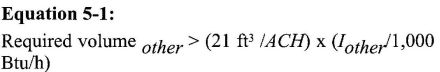
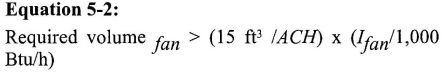
where:
Iother=All appliance other than fan-assisted input in Btu/hour
Ifan = Fan-assisted appliance input in Btu/hour
ACH = Air change per hour (Percent of volume of space exchanged per hour, expressed as a decimal)
507.3 Indoor Opening Size and Location. Openings used to connect indoor spaces shall be sized and located in accordance with the following [NFPA 54:9.3.2.3]:
507.4 Outdoor Combustion Air. Outdoor combustion air shall be provided through opening(s) to the outdoors in accordance with methods Sections 507.4.1 or 507.4.2. The dimension of air openings shall be not less than three (3) inches (80 mm). [NFPA 54:9.3.3]
507.4.1 Two Permanent Opening Method. Two (2) permanent openings, one (1) commencing within twelve (12) inches (300 mm) of the top and one (1) commencing within twelve (12) inches (300 mm) of the bottom of the enclosure shall be provided. The openings shall communicate directly, or by ducts, with the outdoors or spaces that freely or by ducts, with the outdoors or spaces that freely communicate with outdoors as follows [NFPA 54:9.3.3.1]:
507.4.2 One Permanent Opening Method. One (1) permanent opening, commencing within twelve (12) inches (30 mm) of the top of the enclosure, shall be provided. The appliance shall have clearances of not less than one (1) inch (25 mm) from the sides and back and six (6) inches (160 mm) from the front of the appliance. The opening shall directly communicate with the outdoors or shall communicate through a vertical or horizontal duct to the outdoors or spaces that freely communicate with the outdoors [see Figure 5-11] and shall have a minimum free area of the following [NFPA 54:9.3.3.2]:
507.5 Combination Indoor and Outdoor Combustion Air. The use of a combination of indoor and outdoor combustion air shall be in accordance with Section 507.5.1, 507.5.2 and 507.5.3 (See example calculation in NFPA 54, National Fuel Gas Code, Annex J and this chapter— Part II). [NFPA 54:9.3.4]
507.5.1 Indoor Openings. Where used, openings connecting the interior spaces shall comply with Section 507.3. [NFPA 54:9.3.4(1)]
507.5.2 Outdoor openings shall be located in accordance with Sections 507.4.1 or 507.4.2. [NFPA 54:9.3.4(2)]
507.5.3 Outdoor Openings Size. The outdoor openings size shall be calculated in accordance with the following [NFPA 54:9.3.4(3)]:
507.6 Engineered Installations. Engineered combustion air installation shall provide an adequate supply of combustion, ventilation, and dilution air and shall be approved by the Authority Having Jurisdiction. [NFPA 54:9.3.5]
507.7 Mechanical Combustion Air Supply. Where combustion air is provided by a mechanical air supply system, the combustion air shall be supplied from outdoors at the minimum rate of 0.35 cubic feet/min per 1,000 Btu/h (0.034 m3/min per kW) for appliance located within the space.[NFPA 54:9.3.6]
507.7.1 Where exhaust fans are installed, additional air shall be provided to replace the exhausted air. [NFPA 54:9.3.6.1]
507.7.2 Each of the appliances served shall be interlocked to the mechanical air supply system to prevent main burner operation where the mechanical air supply system is not in operation. [NFPA 54:9.3.6.2]
507.7.3 Where combustion air is provided by the building's mechanical ventilation system, the system shall provide the specified combustion air rate in addition to the required ventilation air. [NFPA 54:9.3.6.3]
507.8 Louvers, Grilles, and Screens.
507.9 Combustion Air Ducts. Combustion air ducts shall comply with the following:
Exception: Within dwelling units, unobstructed stud and joist spaces shall not be prohibited from conveying combustion air, provided that not more than one (1) fireblock is removed.
508.0 Other Water Heater Installation Requirements.
508.1 The Authority Having Jurisdiction shall have the authority to require the use of an approved dielectric insulator on the water piping connections of water heaters and related water heating appliances.
508.2 Protection from Seismic Damage. Water heaters shall be anchored or strapped or resist horizontal displacement due to earthquake motion. Strapping shall be at points within the upper one third (1/3) and lower one-third (/) of its vertical dimension. At the lower point, a minimum distance of four (4) inches (102 mm) shall be maintained above the controls with the strapping.
Note: [HCD 1 & HCD 2] Reference Health and Safety Code Section 19211(a) which addresses new, replacement, and existing water heaters.
Note: The applicable subsection of Health and Safety Code Section 19211(a) which addresses new, replacement, and existing water heaters is repeated here for clarity and reads as follows:
Section 19211(a) Notwithstanding Section 19100, all new and replacement water heaters, and all existing residential water heaters shall be braced, anchored, or strapped to resist falling or horizontal displacement due to earthquake motion. At a minimum, any water heater shall be secured in accordance with the California Plumbing Code, or modifications made thereto by a city, county, or city and county pursuant to Section 17958.5.
508.3 A water heater supported from the ground shall rest on level concrete or other approved base extending not less than three (3) inches (76 mm) above the adjoining ground level.
508.4 When a water heater is located in an attic, attic-ceiling assembly, floor-ceiling assembly, or floor-subfloor assembly where damage results from a leaking water heater, a watertight pan of corrosion-resistant materials shall be installed be neath the water heater with not less than three-quarters (¾) of an inch (20 mm) diameter drain to an approved location.
508.5 Relief Valve Discharge. Discharge from a relief valve into a water heater pan shall be prohibited.
508.6 Added or Converted Appliances. When an additional or replacement appliance is installed or an appliance is converted to gas from another fuel, the location in which the appliance is to be operated shall be checked to verify the following [NFPA 54:9.1.2]:
508.6.1 Air for combustion and ventilation is provided where required, in accordance with the provisions of Section 507.0. Where existing facilities are not adequate, they shall be upgraded to Section 507.0 specifications. [NFPA 54:9.1.2(1)]
508.6.2 The installation components and appliances meet the clearances to combustible material provisions of NFPA 54:9.2.2. It shall be determined that the installation and operation of the additional or replacement appliance does not render the remaining appliance unsafe for continued operation. [NFPA 54:9.1.2(2)]
(The following reference was extracted from NFPA 54, National Fuel Gas Code).
9.2.2 Clearance to Combustible Materials. Appliances and their vent connectors shall be installed with clearances from combustible material so their operation will
not create a hazard to persons or property. Minimum clearances between combustible walls and the back and sides of various conventional types of appliances and their vent connectors are specified in Chapters 10 and 12. (Reference can also be made to NFPA 211, Standard for Chimneys, Fireplaces, Vents, and Solid Fuel-Burning Appliances.)
508.6.3 The venting system is constructed and sized in accordance with the provisions of this chapter. Where the existing venting system is not adequate, it shall be upgraded to comply with this chapter. [NFPA 54:9.1.2(3)]
508.7 Types of Gases. It shall be determined whether the gasutilization appliance has been designed for use with the gas to which it will be connected. No attempt shall be made to convert the appliance from the gas specified on the rating plate for use with a different gas without consulting the installation instructions, the serving gas supplier, or the appliance manufacturer for complete instructions. [NFPA 54:9.1.3]
508.8 Safety Shutoff Devices for Unlisted LP-Gas Appliance Used Indoors. Unlisted gas utilization appliances for use with undiluted liquefied petroleum gases and installed indoors shall be equipped with safety shutoff devices of the complete shutoff type. [NFPA 54:9.1.4]
508.9 Use of Air or Oxygen Under Pressure. Where air or oxygen under pressure is used in connection with the gas supply, effective means such as a back-pressure regulator and relief valve shall be provided to prevent air or oxygen from passing back into the gas piping. Where oxygen is used, installation shall be in accordance with NFPA 51, Standard for the Design and Installation of Oxygen-Fuel Gas Systems for Welding, Cutting, and Allied Processes. [NFPA 54:9.1.5]
508.10 Protection of Gas Appliances from Fumes or Gases Other than Products of Combustion. Non-direct vent-type gas appliances installed in beauty shops, barbershops, or other facilities where chemicals that generate corrosive or flammable products such as aerosol sprays are routinely used shall be located in an equipment room separate or partitioned off from other areas with provisions for combustion and dilution air from outdoors. Direct vent appliances shall be installed in accordance with the appliance manufacturer’s installation instructions. [NFPA 54:9.1.6.2]
508.11 Process Air. In addition to air needed for combustion in commercial or industrial processes, process air shall be provided as required for cooling of equipment or material, controlling dew point, heating, drying, oxidation, dilution, safety exhaust, odor control, air for compressors, and for comfort and proper working conditions for personnel. [NFPA 54:9.1.7]
508.12 Building Structural Members.
508.12.1 Structural members of a building shall not pass through gas utilization appliances having an operating temperature exceeding 500°F (260°C). [NFPA 54:9.1.8.1]
508.12.2 Structural members passing through gas utilization appliances having an operating temperature of 500°F (260°C) or less shall be of noncombustible material. Building columns, girders, beams, or trusses shall not be installed within appliances, unless insulation and ventilation are provided to avoid deterioration in strength and ventilation are provided to avoid deterioration in strength and linear expansion of the building structure in either a vertical or a horizontal direction. [NFPA 54:9.1.8.2]
508.12.3 Gas utilization appliances shall be furnished either with load-distributing bases or with a sufficient number of supports to prevent damage to either the building structure or appliance. [NFPA 54:9.1.8.3]
508.12.4 At the locations selected for installation of the gas utilization appliance, the dynamic and static load carrying capacities of the building structure shall be checked to determine whether they are adequate to carry the additional loads. The appliance shall be supported and shall be connected to the piping so as not to exert undue stress on the connections. [NFPA 54:9.1.8.4]
508.13 Flammable Vapors. Gas appliances shall not be installed in areas where the open use, handling, or dispensing of flammable liquids occurs, unless the design, operation, or installation reduces the potential of ignition of the flammable vapors. Gas utilization appliances installed in compliance with Sections 508.14, 508.15, or 508.16 shall be considered to comply with the intent of this provision. [NFPA 54:9.1.9]
508.14 Installation in Residential Garages.
508.15 Installation in Commercial Garages.
508.15.1 Parking Structures. Gas utilization appliances installed in enclosed, basement, and underground parking structures shall be installed in accordance with NFPA 88A, Standard for Parking Structures. [NFPA 54:9.1.11.1]
508.15.2 Repair Garages. Gas utilization appliances installed in repair garages shall be installed in a detached building or room, separated from repair areas by walls or partitions, floors, or floor-ceiling assemblies that are constructed so as to prohibit the transmission of vapors and having a fire-resistance rating of not less than one (1) hour, and that have no openings in the wall separating the repair area within eight (8) feet (2.5 m) of the floor. Wall penetrations shall be fire-stopped. Air for combustion purposes shall be obtained from outside the building. The heating room shall not be used for the storage of combustible materials. [NFPA 54:9.1.11.2]
Exceptions:
- Overhead heaters where installed not less than eight (8) ft (2.5 m) above the floor shall be permitted.
- Heating appliances for vehicle repair areas where there is no dispensing or transferring of Class I or Class II flammable or combustible liquids or liquefied petroleum gas shall be installed in accordance with NFPA 30A, Code for Motor Fuel Dispensing Facilities and Repair Garages. [NFPA 54:9.1.11.2]
508.16 Installation in Aircraft Hangars. Heaters in aircraft hangars shall be installed in accordance with NFPA 409, Standard on Aircraft Hangars. [NFPA 54:9.1.12]
508.17 Gas Appliance Physical Protection. Where it is necessary to locate gas utilization appliances close to a passageway traveled by vehicles or equipment, guardrails or bumper plates shall be installed to protect the appliance from damage. [NFPA 54:9.1.13]
508.18 Venting of Flue Gases. Gas utilization appliances shall be vented in accordance with the provisions of this chapter and NFPA 54, National Fuel Gas Code, Chapter 12. [NFPA 54:9.1.14]
508.19 Extra Device or Attachment. No device or attachment shall be installed on any gas utilization appliance that could in any way impair the combustion of gas. [NFPA 54:9.1.15]
508.20 Adequate Capacity of Piping. When additional gas utilization appliances are being connected to a gas piping system, the existing piping shall be checked to determine if it has adequate capacity (See Section 1209.4.3). Where inadequate, the existing system shall be enlarged as necessary, or separate gas piping of adequate capacity shall be run from the point of delivery to the appliance. [NFPA 54:9.1.16]
508.21 Avoiding Strain on Gas Piping. Gas utilization appliances shall be supported and so connected to the piping as not to exert undue strain on the connections. [NFPA 54:9.1.17]
508.22 Gas Appliance Pressure Regulators. Where the gas supply pressure exceeds that at which the gas utilization appliance is designed to operate or varies beyond the design pressure limits of the appliance, a gas appliance pressure regulator shall be installed. [NFPA 54:9.1.18]
508.23 Venting of Gas Appliance Pressure Regulators. Venting of gas appliance pressure regulators shall comply with the following requirements [NFPA 54:9.1.19]:
508.23.1 Gas appliance pressure regulators requiring access to the atmosphere for successful operation shall be equipped with vent piping leading outdoors or, if the regulator vent is an integral part of the appliance, into the combustion chamber adjacent to a continuous pilot, unless constructed or equipped with a vent limiting means to limit the escape of gas from the vent opening in the event of diaphragm failure. [NFPA 54:9.1.19(1)]
508.23.2 Vent limiting means shall be employed on listed gas appliance pressure regulators only. [NFPA 54:9.1.19(2)]
508.23.3 In the case of vents leading outdoors, means shall be employed to prevent water from entering this piping and also to prevent blockage of vents by insects and foreign matter. [NFPA 54:9.1.19(3)]
508.23.4 Under no circumstances shall a regulator be vented to the gas utilization appliance flue or exhaust system. [NFPA 54:9.1.19(4)]
508.23.5 In the case of vents entering the combustion chamber, the vent shall be located so the escaping a gas will be readily ignited by the pilot and the heat liberated thereby will not adversely affect the normal operation of the safety shutoff system. The terminus of the vent shall be securely held in a fixed position relative to the pilot. For manufactured gas, the need for a flame arrester in the vent piping shall be determined. [NFPA 54:9.1.19(5)]
508.23.6 Vent lines from a gas appliance pressure regulator and bleed lines from a diaphragm-type valve shall not be connected to a common manifold terminating in a combustion chamber. Vent lines shall not terminate in positive-pressure-type combustion chambers. [NFPA 54:9.1.19(6)]
508.24 Bleed Lines for Diaphragm-Type Valves. Bleed lines shall comply with the following requirements [NFPA 54:9.1.20]:
508.24.1 Diaphragm-type valves shall be equipped to convey bleed gas to the outside atmosphere or into the combustion chamber adjacent to a continuous pilot. [NFPA 54:9.1.20(1)]
508.24.2 In the case of bleed lines leading outdoors, means shall be employed to prevent water from entering this piping and also to prevent blockage of vents by insects and foreign matter. [NFPA 54:9.1.20(2)]
508.24.3 Bleed lines shall not terminate in the gas utilization appliance flue or exhaust system. [NFPA 54:9.1.20(3)]
508.24.4 In the case of bleed lines entering the combustion chamber, the bleed line shall be located so the bleed gas will be readily ignited by the pilot and the heat liberated thereby will not adversely affect the normal operation of the safety shutoff system. The terminus of the bleed line shall be securely held in a fixed position relative to the pilot. For manufactured gas, the need for a flame arrester in the bleed line piping shall be determined. [NFPA 54:9.1.20(4)]
508.24.5 Bleed lines from a diaphragm-type valve and vent lines from a gas appliance pressure regulator shall not be connected to a common manifold terminating in a combustion chamber. Bleed lines shall not terminate in positive-pressure-type combustion chambers. [NFPA 54:9.1.20(5)]
508.25 Combination of Appliances. Any combination of gas utilization appliances, attachments, or devices used together in any manner shall comply with the standard that apply to the individual appliance. [NFPA 54:9.1.21]
508.26 Installation Instructions. The installing agency shall conform with the appliance manufacturer’s recommendations
in completing an installation. The installing agency shall leave the manufacturer’s installation, operating, and maintenance instructions in a location on the premises where they will be readily available for reference and guidance for the Authority Having Jurisdiction, service personnel, and the owner or operator. [NFPA 54:9.1.22]
508.27 Protection of Outdoor Appliances. Gas utilization appliances not listed for outdoor installation but installed outdoors shall be provided with protection to the degree that the environment requires. Appliances listed for outdoor installation shall be permitted to be installed without protection in accordance with the provisions of its listing (See NFPA 54:9.2.1). [NFPA 54:9.1.23]
(The following references were extracted from NFPA 54, National Fuel Gas Code.)
9.2 Accessibility and Clearance.
9.2.1 Accessibility for Service. Gas utilization appliances shall be located with respect to building construction and other equipment so as to permit access to the gas utilization appliance. Sufficient clearance shall be maintained to permit cleaning of heating surfaces; the replacement of filters, blowers, motors, burners, controls, and vent connections; the lubrication of moving parts where necessary; the adjustment and cleaning of burners and pilots; and the proper functioning of explosion vents, if provided. For attic installation, the passageway and servicing area adjacent to the appliance shall be floored.
509.0 Appliances on Roofs.
509.1 General.
509.2 Installation of Appliances on Roofs.
509.3 Access to Appliances on Roofs.
509.3.1 Gas utilization appliances located on roofs or other elevated locations shall be accessible. [NFPA 54:9.4.3.1]
509.3.2 Buildings exceeding fifteen (15) feet (4.6 m) in height shall have an inside means of access to the roof, unless other means acceptable to the Authority Having Jurisdiction are used. [NFPA 54:9.4.3.2]
509.3.3 The inside means of access shall be a permanent, or fold-away inside stairway or ladder, terminating in an enclosure, scuttle, or trap door. Such scuttles or trap doors shall be not less than twenty-two (22) inches x twenty-four (24) inches (560 mm x 610 mm) in size, shall open easily and safely under all conditions, especially snow; and shall be constructed so as to permit access from the roof side unless deliberately locked on the inside.
Not less than six (6) feet (1.8 m) of clearance shall be available between the access opening and the edge of the roof or similar hazard, or rigidly fixed rails or guards not less than forty-two (42) inches (1.1 m) in height shall be provided on the exposed side. Where parapets or other building structures are utilized in lieu of guards or rails, they shall be not less than forty-two (42) inches (1.1 m) in height.[NFPA 54:9.4.3.3]
509.3.4 Permanent lighting shall be provided at the roof access. The switch for such lighting shall be located inside the building near the access means leading to the roof. [NFPA 54:9.4.3.4]
509.4 Appliances in Attics.
509.4.1 Attic Access. An attic in which an appliance is installed shall be accessible through an opening and passageway not less than as large as the largest component of the appliance, and not less than twenty-two (22) inches x thirty (30) inches (560 mm x 760 mm). [NFPA 54:9.5.1]
509.4.2 Where the height of the passageway is less than six (6) feet (1.8 m), the distance from the passageway access to the appliance shall not exceed twenty (20) feet (6.1 m) measured along the centerline of the passageway. [NFPA 54:9.5.1.1]
509.4.3 The passageway shall be unobstructed and shall have solid flooring not less than twenty-four (24) inches (610 mm) wide from the entrance opening to the appliance. [NFPA 54:9.5.1.2]
509.4.4 Work Platform. A level working platform not less than thirty (30) inches (760 mm) by thirty (30) inches (760 mm) shall be provided in front of the service side of the appliance. [NFPA 54:9.5.2]
509.4.5 Lighting and Convenience Outlet. A permanent 120-volt receptacle outlet and a lighting fixture shall be installed near the appliance. The switch controlling the lighting fixture shall be located at the entrance to the passageway. [NFPA 54:9.5.3]
510.0 Venting of Appliances.
510.1 General. This section recognizes that the choice of venting materials and the methods of installation of venting systems are dependent on the operating characteristics of the appliance. [NFPA 54:12.2.1]
510.1.1 Categories. The operating characteristics of vented gas utilization appliances can be categorized with respect to (1) positive or negative pressure within the venting system, and (2) whether or not the appliance generates flue or vent gases that can condense in the venting system. See NFPA 54, National Fuel Gas Code, Section 3.3 for the definition of these vented appliance categories. [NFPA 54:12.2.2]
510.1.2 Installation. Listed vents shall be installed in accordance with Chapter 5 and the manufacturer’s installation instructions. [NFPA 54:12.2.3]
510.1.3 Appliance vents shall not discharge into any space enclosed by screens having openings less than one-fourth (¼) inch (6.4 mm) mesh.
510.2 Specification for Venting.
510.2.1 Connection to Venting Systems. Except as permitted in Sections 510.2.2 through 510.2.6, gas utilization appliances shall be connected to venting systems. [NFPA 54:12.3.1]
510.2.2 Appliances Not Required to Be Vented. The following appliances shall not be required to be vented [NFPA 54:12.3.2]:
510.2.2.1 Listed ranges. [NFPA 54:12.3.2(1)]
510.2.2.2 Built-in domestic cooking units listed and marked for optional venting. [NFPA 54:12.3.2(2)]
510.2.2.3 Listed hot plates and listed laundry stoves. [NFPA 54:12.3.2(3)]
510.2.2.4 Listed Type 1 clothes dryers shall be exhausted to the outside air. [NFPA 54:12.3.2(4)]
510.2.2.5 A single listed booster-type (automatic instantaneous) water heater, when designed and used solely for the sanitizing rinse requirements of a dishwashing machine, provided that the appliance is installed with the draft hood in place and unaltered if a draft hood is required, in a commercial kitchen having a mechanical exhaust system; where installed in this manner, the draft hood outlet shall be not less than thirty-six (36) inches (910 mm) vertically and six (6) inches (150 mm) horizontally from any surface other than the appliance. [NFPA 54:12.3.2(5)]
510.2.2.6 Listed refrigerators. [NFPA 54:12.3.2(6)]
510.2.2.7 Counter appliances. [NFPA 54:12.3.2(7)]
510.2.2.8 Direct gas-fired makeup air heaters. [NFPA 54:12.3.2(9)]
510.2.2.9 Other appliances listed for unvented use and not provided with flue collars. [NFPA 54:12.3.2(10)]
510.2.2.10 Specialized appliance of limited input such as laboratory burners or gas lights. [NFPA 54:12.3.2(11)]
Where appliances in Sections 510.2.2.5 through 510.2.2.10 are installed so the aggregate input rating exceeds 20 Btu/h/ft.3 (207 W/m3) of room or space in which it is installed, one (1) or more shall be provided with venting systems or other approved means for removing the vent gases to the outside atmosphere so the aggregate input rating of the remaining unvented appliance does not exceed 20 Btu/h/ft.3 (207W/m3). Where the calculation includes the volume of an adjacent room or space, the room or space in which the appliance is installed shall be directly connected to the adjacent room or space by a doorway, archway, or other opening of comparable size that cannot be closed. [NFPA 54:12.3.2]
510.2.3 Ventilating Hoods. Ventilating hoods and exhaust system shall be permitted to be used to vent gas utilization appliances installed in commercial applications (See Section 510.3.5) and to vent industrial appliances, particularly where the process itself requires fume disposal. [NFPA 54:12.3.3]
510.2.4 Well-Ventilated Spaces. The operation of industrial appliances such that its flue gases are discharged directly into a large and well-ventilated space shall be permitted. [NFPA 54:12.3.4]
510.2.5 Direct-Vent Appliances. Listed direct-vent gas utilization appliances shall be considered properly vented where installed in accordance with the terms of its listing, the manufacturer’s instructions, and Section 510.8.3 of this code. [NFPA 54:12.3.5]
510.2.6 Appliances with Integral Vents. Gas utilization appliances incorporating integral venting means shall be considered properly vented where installed in accordance with its listing, the manufacturer’s instructions, and Sections 510.8.1 and 510.8.2 of this code. [NFPA 54:12.3.6]
510.3 Design and Construction.
510.3.1 Minimum Safe Performance. A venting system shall be designed and constructed so as to develop a positive flow adequate to remove flue or vent gases to the outside atmosphere. [NFPA 54:12.1]
510.3.2 Appliance Draft Requirements. A venting system shall satisfy the draft requirements of the appliance in accordance with the manufacturer’s instructions. [NFPA 54:12.4.1]
510.3.3 Design and Construction. Gas utilization appliances required to be vented shall be connected to a venting system designed and installed in accordance with the provisions of Sections 510.4 through 510.15 of this code. [NFPA 54:12.4.2]
510.3.4 Mechanical Draft Systems.
510.3.4.1 Mechanical draft systems shall be listed and shall be installed in accordance with the terms of their listing and both the appliance and the mechanical draft system manufacturer’s instructions. [NFPA 54:12.4.3.1]
510.3.4.2 Gas utilization appliances requiring venting shall be permitted to be vented by means of mechanical draft systems of either forced or induced draft design. [NFPA 54:12.4.3.2]
Exception: Incinerators.
510.3.4.3 Forced draft systems and portions of induced draft systems under positive pressure during operation shall be designed and installed so as to prevent leakage of flue or vent gases into a building. [NFPA 54:12.4.3.3]
510.3.4.4 Vent connectors serving appliances vented by natural draft shall not be connected into any portion of mechanical draft systems operating under positive pressure. [NFPA 54:12.4.3.4]
510.3.4.5 Where a mechanical draft system is employed, provision shall be made to prevent the flow of gas to the main burners when the draft system is not performing so as to satisfy the operating requirements of the appliance for safe performance. [NFPA 54:12.4.3.5]
510.3.4.6 The exit terminals of mechanical draft systems shall be not less than seven (7) feet (2.1 m) above finished grade where located adjacent to public walkways and shall be located as specified in Sections 510.8.1 and 510.8.2 of this code. [NFPA 54:12.4.3.6]
510.3.5 Ventilating Hoods and Exhaust Systems.
510.3.5.1 Ventilating hoods and exhaust systems shall be permitted to be used to vent gas utilization appliances installed in commercial appliances. [NFPA 54:12.4.4.1]
510.3.5.2 Where automatically operated appliances, other than commercial cooking appliances, are vented through a ventilating hood or exhaust system equipped with a damper or with a power means of exhaust, provisions shall be made to allow the flow of gas to the main burners only when the damper is open to a position to properly vent the appliance and when the power means of exhaust is in operation. [NFPA 54:12.4.4.2]
510.3.6 Circulating Air Ducts and Furnace Plenums. Venting systems shall not extend into or pass through any fabricated air duct or furnace plenum. [NFPA 54-09:12.4.5.1]
510.4 Type of Venting System to Be Used.
510.4.1 The type of venting system to be used shall be in accordance with Table 5-2. [NFPA 54:12.5.1]
510.4.2 Plastic Piping. Plastic piping used for venting appliances listed for use with such venting materials shall be approved. [NFPA 54:12.5.2]
510.4.3 Plastic Vent Joints. Plastic pipe and fittings used to vent appliances shall be installed in accordance with the appliance manufacturer’s installation instructions. Where primer is required, it shall be of a contrasting color. [NFPA 54-09:12.5.3]
510.4.4 Special Gas Vent. Special gas vent shall be listed and installed in accordance with the terms of the special gas vent listing and the manufacturer’s instructions. [NFPA 54:12.5.3]
510.5 Masonry, Metal, and Factory-Built Chimneys.
510.5.1 Listing or Construction.
510.5.1.1 Factory-built chimneys shall be installed in accordance with their listing and the manufacturer’s instructions. Factory-built chimneys used to vent appliances that operate at positive vent pressure shall be listed for such application. [NFPA 54:12.6.1.1]
510.5.1.2 Metal Chimneys shall be built and installed in accordance with NFPA 211, Standard for Chimneys, Fireplaces, Vents, and Solid Fuel-Burning Appliances. [NFPA 54:12.6.1.2]
510.5.1.3 Masonry chimneys shall be built and installed in accordance with NFPA 211, Standard for Chimneys, Fireplaces, Vents, and Solid Fuel-Burning Appliances, and lined with approved clay fluelining, a listed chimney lining system, or other approved material that will resist corrosion, erosion, softening, or cracking from vent gases at temperatures up to 1,800°F (982°C). [NFPA 54:12.6.1.3]
Exception: Masonry chimney flues lined with a chimney lining system specifically listed for use with listed gas appliances with draft hoods, Category I appliances, and other gas appliances listed for use with Type B vents shall be permitted. The liner shall be installed in accordance with the liner manufacturer’s instructions and the terms of the listing. A permanent identifying label shall be attached at the point where the connection is to be made to the line. The label shall read: “This chimney liner is for appliances that burn gas only. Do not connect to solid- or liquid-fuel-burning appliances or incinerators.” [NFPA 54:12.6.1.3]
510.5.2 Termination.
510.5.2.1 A chimney for a residential-type or low-heat gas utilization appliance shall extend at least three (3) feet (0.9 m) above the highest point where it passes through the roof of a building and at least two (2) feet (0.6 m) exceeding any portion of a
building within a horizontal distance of ten (10) feet (3.0 m) (See Figure 5-1). [NFPA 54: 12.6.2.1]
510.5.2.2 A chimney for a medium-heat appliance shall extend at least ten (10) feet (3.0 m) exceeding any portion of any building within twenty-five (25) feet (7.6 m). [NFPA 54: 12.6.2.2]
510.5.2.3 A chimney shall extend at least five (5) feet (1.5 m) above the highest connected appliance draft hood outlet or flue collar. [NFPA 54: 12.6.2.3]
510.5.2.4 Decorative shrouds shall not be installed at the termination of factory-built chimneys except where such shrouds are listed and labeled for use with the specific factory-built chimney system and are installed in accordance with manufacturer’s installation instructions. [NFPA 54: 12.6.2.4]
510.5.3 Size of Chimneys. The effective area of a chimney venting system serving listed gas appliances with draft hoods, Category I appliances, and other appliances listed for use with Type B vents shall be in accordance with one of the following methods [NFPA 54: 12.6.3.1]:
510.5.4 Inspection of Chimneys.
Exception: Existing chimneys shall be permitted to have their use continued where an appliance is re-placed by an appliance of similar type, input rating, and efficiency, where the chimney complies with Section 510.5.4, and the sizing of the chimney is in accordance with Section 510.5.3.
![FIGURE 5-1 TYPICAL TERMINATION LOCATIONS FOR CHIMNEYS AND SINGLE-WALL METAL PIPES SERVING RESIDENTIAL-TYPE AND LOW-HEAT APPLIANCE [NFPA 54: FIGURE 12.6.2.1]](images/gov.ca.bsc.2010.05_081_01.jpg)
FIGURE 5-1 TYPICAL TERMINATION LOCATIONS FOR CHIMNEYS AND SINGLE-WALL METAL PIPES SERVING RESIDENTIAL-TYPE AND LOW-HEAT APPLIANCE [NFPA 54: FIGURE 12.6.2.1]
81510.5.5 Chimney Serving Appliances Burning Other Fuels.
510.5.5.1 Gas utilization appliances shall not be connected to a chimney flue serving a separate appliance designed to burn solid fuel. [NFPA 54:12.6.5.1]
510.5.5.2 Where one (1) chimney serves gas utilization appliances and liquid fuel-burning appliances, the appliance shall be connected through separate openings or shall be connected through a single opening where joined by a suitable fitting located as close as practical to the chimney. Where two (2) or more openings are provided into one (1) chimney flue, they shall be at different levels. Where the gas utilization appliance is automatically controlled, it shall be equipped with a safety shutoff device. [NFPA 54:12.6.5.2]
![FIGURE 5-2 GAS VENT TERMINATION LOCATIONS FOR LISTED CAPS 12 INCH (300 MM) OR LESS IN SIZE NOT LESS THAN 8 FEET (2.4m) FROM A VERTICAL WALL [NFPA 54: FIGURE 12.7.2 AND TABLE 12.7.2]](images/gov.ca.bsc.2010.05_082_01.jpg)
FIGURE 5-2 GAS VENT TERMINATION LOCATIONS FOR LISTED CAPS 12 INCH (300 MM) OR LESS IN SIZE NOT LESS THAN 8 FEET (2.4m) FROM A VERTICAL WALL [NFPA 54: FIGURE 12.7.2 AND TABLE 12.7.2]
![FIGURE 5-3 PLAN VIEW OF PRACTICAL SEPARATION METHOD FOR MULTISTORY GAS VENTING.[NFPA 54: FIGURE 12.7.4.2]](images/gov.ca.bsc.2010.05_082_02.jpg)
FIGURE 5-3 PLAN VIEW OF PRACTICAL SEPARATION METHOD FOR MULTISTORY GAS VENTING.[NFPA 54: FIGURE 12.7.4.2]
| GAS UTILIZATION APPLIANCES | TYPE OF VENTING SYSTEM |
|---|---|
| Listed Category 1 appliances | Type B gas vent (510.6) |
| Listed appliances equipped with draft hood | Chimney (510.5) |
| Single-wall metal pipe (510.7) | |
| Appliance listed for Type B gas vent | Listed chimney lining system for gas venting (510.5.1.3) |
| Special gas vent listed for this appliance (510.4.4) | |
| Listed vented wall furnaces | Type B-W gas vent (510.6, 510.6.2.2) |
| Category II appliances | As specified or furnished |
| Category III appliances | By manufacturers of listed appliance (510.4.2, 510.4.4) |
| Category IV appliances | |
| Incinerators, outdoors | Single-wall metal pipe (510.7, 510.7.3) |
| Incinerators, indoors | Chimney (510.5) |
| Appliances that can be converted to use of solid fuel | |
| Unlisted combination gas- and oil-burning appliances | |
| Combination gas- and solid-fuel-burning appliances | |
| Appliances listed for use with chimneys only | |
| Unlisted appliances | |
| Listed combination gas- and oil-burning appliances | Type L vent (510.6) or chimney (510.5) |
| Decorative appliance in vented fireplace | Chimney [UMC 907.2(3)] |
| Gas-fired toilets | Single-wall metal pipe (510.7, NFPA 54: 10.25.3) |
| Direct-vent appliances | See 510.2.5 |
| Appliances with integral vent | See 510.2.6 |
510.5.5.3 A listed combination gas- and solid-fuel-burning appliance connected to a single chimney flue shall be equipped with a manual reset device to shut off gas to the main burner in the event of sustained backdraft or flue gas spillage. The chimney flue shall be sized to properly vent the appliance. [NFPA 54: 12.6.5.3]
510.5.5.4 A single chimney flue serving a listed combination gas- and oil-burning appliance shall be sized to properly vent the appliance. [NFPA 54: 12.6.5.4]
510.5.6 Support of Chimneys. Portions of chimneys shall be supported for the design and weight of the materials employed. Listed factory-built chimneys shall be supported and spaced in accordance with their listings and the manufacturer’s instructions. [NFPA 54:12.6.6]
510.5.7 Cleanouts. Where a chimney that formerly carried flue products from liquid- or solid-fuel-burning appliances is used with an appliance using fuel gas, an accessible cleanout shall be provided. The cleanout shall have a tight-fitting cover and be installed so its upper edge is at least six (6) inches (150 mm) below the lower edge of the lowest chimney inlet opening. [NFPA 54: 12.6.7]
510.5.8 Space Surrounding Lining or Vent.
510.5.8.1 The remaining space surrounding a chimney liner, gas vent, special gas vent, or plastic piping installed within a masonry chimney flue shall not be used to vent another appliance. [NFPA 54: 12.6.8.1]
Exception: The insertion of another liner or vent within the chimney as provided in this code and the liner or vent manufacturer’s instructions.
510.5.8.2 The remaining space surrounding a chimney liner, gas vent, special gas vent, or plastic piping installed within a masonry chimney flue shall not be used to supply combustion air. [NFPA 54: 12.6.8.2]
Exception: Direct-vent gas-fired appliances designed for installation in a solid-fuel-burning fire-place where installed in accordance with the listing and the manufacturer’s instruction.
510.6 Gas Vents.
510.6.1 A gas vent passing through a roof shall extend through the entire roof flashing, roof jack, or roof thimble and be terminated with a listed termination cap. [NFPA 54: 12.7.2(6)]
510.6.1.1 Type B or Type L vents shall extend in a generally vertical direction with offsets not exceeding 45 degrees, except that a vent system having not more than one 60 degree offset shall be permitted. Any angle greater than 45 degrees from the vertical is considered horizontal. The total horizontal distance of a vent plus the horizontal vent connector serving draft-hood-equipped appliances shall not exceed 75 percent of the vertical height of the vent. [NFPA 54: 12.7.3.2]
Exception: Systems designed and sized as provided in this chapter or in accordance with other approved engineering methods.
510.6.1.2 Screws, rivets and other fasteners shall not penetrate the inner wall of double wall gas vents.
510.6.2 A gas vent shall terminate in accordance with one of the following [NFPA 54: 12.7.2(1)]:
510.6.2.1 A Type B or a Type L gas vent shall terminate at least five (5) feet (1.5 m) in vertical height above the highest connected appliance draft hood or flue collar.[NFPA 54:12.7.2(2)]
510.6.2.2 A Type B-W gas vent shall terminate at least twelve (12) feet (3.7 m) in vertical height above the bottom of the wall furnace. [NFPA 54:12.7.2(3)]
510.6.2.3 A gas vent extending through an exterior wall shall not terminate adjacent to the wall or below eaves or parapets, except as provided in Sections 510.2.5 and 510.3.4. [NFPA 54: 12.7.2(4)]
510.6.2.4 Decorative shrouds shall not be installed at the termination of gas vents except where such shrouds are listed for use with the specific gas venting system and are installed in accordance with manufacturer’s installation instructions. [NFPA 54: 12.7.2(5)]
510.6.2.5 Gas vents shall extend through the roof flashing, roof jack, or roof thimble and terminate with a listed cap or listed roof assembly. [NFPA 54: 12.7.2(6)]
510.6.2.6 A gas vent shall terminate at least three (3) feet (0.9 m) above a forced air inlet located within ten (10) feet (3.0 m). [NFPA 54: 12.7.2(7)]
510.6.3 Size of Gas Vents. Venting systems shall be sized and constructed in accordance with NFPA 54, National Fuel Gas Code, Chapter 13 or other approved engineering methods and the gas vent and gas appliance manufacturer’s instructions. [NFPA 54: 12.7.3]
510.6.3.1 Category I Appliances. The sizing of natural draft venting systems serving one (1) or more listed appliances equipped with a draft hood or appliances listed for use with Type B gas vent, installed in a single story of a building, shall be in accordance with one of the following methods [NFPA 54: 12.7.3.1]:
510.6.3.2 Category II, Category III, and Category IV Appliances. The sizing of gas vents for Category II, Category III, and Category IV gas utilization appliances shall be in accordance with the equipment manufacturer’s instructions. [NFPA 54: 12.7.3.3]
510.6.3.3 Sizing. Chimney venting systems using mechanical draft shall be sized in accordance with approved engineering methods. [NFPA 54: 12.7.3.4]
510.6.4 Gas Vents Serving Appliances on More Than One Floor.
510.6.4.1 A common gas vent shall be permitted in multistory installations to vent Category I gas utilization appliances located on more than one (1) floor level, provided the venting system is designed and installed in accordance with approved engineering methods.
For the purpose of this section, crawl spaces, basements, and attics shall be considered as floor levels. [NFPA 54:12.7.4.1]
510.6.4.2 Gas utilization appliances connected to the common vent shall be located in rooms separated from a habitable space. Each of these rooms shall have provisions for an adequate supply of combustion, ventilation, and dilution air that is not supplied from a habitable space (See Figure 5-3). [NFPA 54:12.7.4.2]
The size of the connectors and common segments of multistory venting systems for gas utilization appliances listed for use with Type B double-wall gas vent shall be in accordance with Table 5-14, provided [NFPA 54:12.7.4.3]:
510.6.5 Support of Gas Vents. Gas vents shall be supported and spaced in accordance with their listings and the manufacturer’s instructions. [NFPA 54:12.7.5]
510.6.6 Marking. In those localities where solid and liquid fuels are used extensively, gas vents shall be permanently identified by a label attached to the wall or ceiling at a point where the vent connector enters the gas vent. The label shall read: “This gas vent is for appliances that burn gas. Do not connect to solid- or liquid-fuel-burning appliances or incinerators. ” The Authority Having Jurisdiction shall determine whether its area constitutes such a locality. [NFPA 54:12.7.6]
510.7 Single-Wall Metal Pipe.
510.7.1 Construction. Single-wall metal pipe shall be constructed of galvanized sheet steel not less than 0.0304 inch (0.7 mm) thick or of other approved, noncombustible, corrosion-resistant material. [NFPA 54:12.8.1]
510.7.2 Cold Climate. Uninsulated single-wall metal pipe shall not be used outdoors in cold climates for venting gas utilization appliances. For venting appliances in regions where the 99 percent winter design temperature is below 32°F (0°C). [NFPA 54:12.8.2]
510.7.3 Termination. The termination of single-wall metal pipe shall comply with the following requirements [NFPA 54:12.8.3]:
510.7.3.1 Single-wall metal pipe shall terminate at least five (5) feet (1.5 m) in vertical height above the highest connected appliance draft hood outlet or flue collar. [NFPA 54:12.8.3(1)]
510.7.3.2 Single-wall metal pipe shall extend at least two (2) feet (0.6 m) above the highest point where it passes through the roof of a building and at least (2) feet (0.6 m) exceeding any portion of a building within a horizontal distance of ten (10) feet (3.1 m) (See Figure 5-1). [NFPA 54:12.8.3(2)]
510.7.3.3 An approved cap or roof assembly shall be attached to the terminus of a single-wall metal pipe [Also see Section 510.7.4.4]. [NFPA 54:12.8.3(3)]
510.7.4 Installation with Appliances Permitted by 510.4.1.
510.7.4.1 Prohibited Use. Single-wall metal pipe shall not be used as a vent in dwellings and residential occupancies. [NFPA 54-09: 12.8.4.1]
510.7.4.2 Single-wall metal pipe shall be used only for runs directly from the space in which the gas utilization appliance is located through the roof or exterior wall to the outer air. A pipe passing through a roof shall extend without interruption through the roof flashing, roof jacket, or roof thimble. [NFPA 54:12.8.4.1]
510.7.4.3 Single-wall metal pipe shall not originate in any unoccupied attic or concealed space and shall not pass through any attic, inside wall, concealed space, or floor. For the installation of a single-wall metal pipe through an exterior combustible wall, see Section 510.10.14.3. [NFPA 54:12.8.4.2]
510.7.4.4 Single-wall metal pipe used for venting an incinerator shall be exposed and readily examinable for its full length and shall have suitable clearances maintained. [NFPA 54:12.8.4.3]
510.7.4.5 Minimum clearances from single-wall metal pipe to combustible material shall be in accordance with Table 5-3. Reduced clearances from single-wall metal pipe to combustible material shall be as specified for vent connectors in Table 5-4. [NFPA 54:12.8.4.4]
510.7.4.6 Single-wall metal pipe shall not pass through a combustible exterior wall unless guarded at the point of passage by a ventilated metal thimble not smaller than the following [NFPA 54:12.11.14.2]:
Exception: In lieu of thimblc protection, combustible material in the wall shall be removed a sufficient distance from the metal pipe to provide the specified clearance from such metal pipe to combustible material. Any material used to close up such opening shall be noncombustible.
510.7.4.7 Where a single-wall metal pipe passes through a roof constructed of combustible material, a noncombustible, nonventilating thimble shall be used at the point of passage. The thimble shall extend not less than eighteen (18) inches (460 mm) above and six (6) inches (150 mm) below the roof with the annular space open at the bottom and closed only at the top. The thimble shall be sized in accordance with Section 510.7.4.6. [NFPA 54:12.8.4.5]
510.7.5 Size of Single-Wall Metal Pipe. Single-wall metal piping shall comply with the following requirements [NFPA 54:12.8.5]:
510.7.5.1 A venting system of a single-wall metal pipe shall be sized in accordance with one of the following methods and the gas appliance manufacturer’s instructions [NFPA 54:12.8.5(1)]:
| MINIMUM DISTANCE FROM COMBUSTIBLE MATERIAL | ||||
|---|---|---|---|---|
| APPLIANCE | LISTED TYPE B GAS VENT MATERIAL | LISTED TYPE L VENT MATERIAL | SINGLE-WALL METAL PIPE | FACTORY-BUILT CHIMNEY SECTIONS |
| Listed appliances with draft hoods and appliances listed for use with Type B gas vents | As listed | As listed | 6 in. | As listed |
| Residential boilers and furnaces with listed gas conversion burner and with draft hood | 6 in. | 6 in. | 9 in. | As listed |
| Residential appliances listed for use with Type L vents | Not permitted | As listed | 9 in. | As listed |
| Listed gas-fired toilets | Not permitted | As listed | As listed | As listed |
| Unlisted residential appliances with draft hood | Not permitted | 6 in. | 9 in. | As listed |
| Residential and low-heat appliances other than those above | Not permitted | 9 in. | 18 in. | As listed |
| Medium-heat appliances | Not permitted | Not permitted | 36 in. | As listed |
| For SI units, 1 in.= 25.4 mm. | ||||
| Note: These clearances shall apply unless the listing of an appliance or connector specifics clearances, in which case the listed clearances shall apply. | ||||
| WHERE THE REQUIRED CLEARANCE WITH NO PROTECTION FROM APPLIANCE, VENT CONNECTOR, OR SINGLE-WALL METAL PIPE IS: | ||||||||||
|---|---|---|---|---|---|---|---|---|---|---|
| 36 in. | 18 in. | 12 in. | 9 in. | 6 in. | ||||||
| ALLOWABLE CLEARANCES WITH SPECIFIED PROTECTION (in.) | ||||||||||
| TYPE OF PROTECTION APPLIED TO AND COVERING SURFACES OF COMBUSTIBLE MATERIAL WITHIN THE DISTANCE SPECIFIED AS THE REQUIRED CLEARANCE WITH NO PROTECTION [SEE FIGURES 5-4 THROUGH 5-6] | USE COLUMN 1 FOR CLEARANCE ABOVE APPLIANCE OR HORIZONTAL CONNECTOR. COLUMN 2 FOR CLEARANCES FROM APPLIANCES, VERTICAL CONNECTOR, AND SINGLE-WALL METAL PIPE | |||||||||
| ABOVE COLUMN 1 | SIDES AND REAR COLUMN 2 | ABOVE COLUMN 1 | SIDES AND REAR COLUMN 2 | ABOVE COLUMN 1 | SIDES AND REAR COLUMN 2 | ABOVE COLUMN 1 | SIDES AND REAR COLUMN 2 | ABOVE COLUMN 1 | SIDES AND REAR COLUMN 2 | |
| (1) 3½ in. thick masonry wall without ventilated air space | -- | 24 | -- | 12 | -- | 9 | -- | 6 | -- | 5 |
| (2) ½ in. insulation board over 1 in. glass fiber or mineral wool batts | 24 | 18 | 12 | 9 | 9 | 6 | 6 | 5 | 4 | 3 |
| (3) 0.024 sheet metal over 1 in. glass fiber or mineral wool batts reinforced with wire on rear face with ventilated air space | 18 | 12 | 9 | 6 | 6 | 4 | 5 | 3 | 3 | 3 |
| (4) 3½ in. thick masonry wall with ventilated air space | -- | 12 | -- | 6 | -- | 6 | -- | 6 | -- | 6 |
| (5) 0.024 sheet metal with ventilated air space | 18 | 12 | 9 | 6 | 6 | 4 | 5 | 3 | 3 | 2 |
| (6) ½ in. thick insulation board with ventilated air space | 18 | 12 | 9 | 6 | 6 | 4 | 5 | 3 | 3 | 3 |
| (7) 0.024 sheet metal with ventilated air space over 0.024 sheet metal with 0.024 sheet metal with ventilated air space | 18 | 12 | 9 | 6 | 6 | 4 | 5 | 3 | 3 | 3 |
| (8) 1 in. glass fiber or mineral wool batts sandwiched between two sheets 0.024 sheet metal with ventilated air space | 18 | 12 | 9 | 6 | 6 | 4 | 5 | 3 | 3 | 3 |
| For SI units, 1 in. = 25.4 mm. | ||||||||||
| Notes: | ||||||||||
| 1 Reduction of clearances from combustible materials shall not interfere with combustion air, draft hood clearance and relief, and accessibility of servicing. | ||||||||||
| 2 Clearances shall be measured from the outer surface of the combustible material to the nearest point on the surface of the appliance, disregarding any intervening protection applied to the combustible material. | ||||||||||
| 3 Spacers and ties shall be of noncombustible material. No spacer or tie shall be used directly opposite the appliance or connector. | ||||||||||
| 4 Where clearance reduction systems use a ventilated air space, adequate provision for air circulation shall be provided as described. [See Figure 5-5 and Figure 5-6.] | ||||||||||
| 5 There shall be at least one (1) in. (25 mm) between clearance reduction systems and combustible walls and ceilings for reduction systems using a ventilated air space. | ||||||||||
| 6 Where a wall protector is mounted on a single flat wall away from corners, it shall have a minimum one (1) inch (25 mm) air gap. To provide adequate air circulation, the bottom and top edges, or only the side and top edges, or edges shall be left open. | ||||||||||
| 7 Mineral wool batts (blanket or board) shall have a minimum density of eight (8) Ib/ft.3 (128 kg/m 3) and a minimum melting point of 1500° F (816°C). | ||||||||||
| 8 Insulation material used as part of a clearance reduction system shall have a thermal conductivity of 1.0 Btu in./ft2 h-°F (0.144 W/m-K) or less. | ||||||||||
| 9 There shall be at least (1) inch (25 mm) between the appliance and the protector. In no case shall the clearance between the appliance and the combustible surface be reduced below that allowed in this table. | ||||||||||
| 10 Clearances and thicknesses are minimum; larger clearances and thicknesses are acceptable. | ||||||||||
| 11 Listed single-wall connectors shall be installed in accordance with the terms of their listing and the manufacturer's instructions. | ||||||||||
![FIGURE 5-4 EXTENT OF PROTECTION NECESSARY TO REDUCE CLEARANCES FROM GAS APPLIANCES OR VENT CONNECTORS [NFPA 54: FIGURE 10.3.2.2(1)]](images/gov.ca.bsc.2010.05_087_01.jpg)
FIGURE 5-4 EXTENT OF PROTECTION NECESSARY TO REDUCE CLEARANCES FROM GAS APPLIANCES OR VENT CONNECTORS [NFPA 54: FIGURE 10.3.2.2(1)]
![FIGURE 5-5 WALL PROTECTION REDUCTION SYSTEM.[NFPA 54: FIGURE 10.3.2.2(2)]](images/gov.ca.bsc.2010.05_087_02.jpg)
FIGURE 5-4 EXTENT OF PROTECTION NECESSARY TO REDUCE CLEARANCES FROM GAS APPLIANCES OR VENT CONNECTORS [NFPA 54: FIGURE 10.3.2.2(1)]
FIGURE 5-5 WALL PROTECTION REDUCTION SYSTEM.[NFPA 54: FIGURE 10.3.2.2(2)]
![FIGURE 5-6 MASONRY CLEARANCE REDUCTION SYSTEM.[NFPA 54: FIGURE 10.3.2.2(3)]](images/gov.ca.bsc.2010.05_087_03.jpg)
FIGURE 5-6 MASONRY CLEARANCE REDUCTION SYSTEM.[NFPA 54: FIGURE 10.3.2.2(3)]
510.7.5.2 Where a single wall metal pipe is used and has a shape other than round, it shall have an equivalent effective area equal to the effective area of the round pipe for which it is substituted, and the internal dimension of the pipe shall be atleast two (2) inches (50 mm). [NFPA 54:12.8.5(2)].
510.7.5.3 The vent cap or a roof assembly shall have a venting capacity at least that of the pipe to which it is attached. [NFPA 54:12.8.5(3)]
510.7.6 Support of Single-Wall Metal Pipe. portions of single wall metal pipe shall be supported for the design and weight of the material employed. [NFPA 54:12.8.6]
510.7.7 Marking. Single-wall metal pipe shall comply with the marking provisions of Section 510.6.6. [NFPA 54:12.8.7]
510.8 Through-the -Wall Vent Termination (See Figure 5-12).
510.8.1 A mechanical draft venting system shall terminate at least three (3) feet (0.9 m) above any forced air inlet located within ten (10) feet (3.1 m). [NFPA 54:12.9.1]
Exceptions:
510.8.2 A mechanical draft venting system of other than direct-vent type shall terminate at least four (4) feet (1.2 m) below, four (4) feet (1.2 m). horizontally from, or one (1) foot (300 mm) above any door, operable window, or gravity air inlet into any building. The bottom of the vent terminal shall be located at least twelve (12) inches (300 mm) above finished grade. [NFPA 54:12.9.2]
510.8.3 The vent terminal of a direct-vent appliance with an input of 10,000 Btu/h (3 k W) or less shall be located at least (6) inches (150 mm) from any air opening into a building, and such an appliance with an input over 10,000 Btu/h (3 kW) but not over 50,000 Btu/h (14.7 kW) shall be installed with a nine (9) inch (230 mm) vent termination clearance, and an appliance with an input over 50,000 Btu/h (14.7 kW) shall have at least a twelve (12) inch (300 mm) vent termination clearance. The bottom of the vent terminal and the air intake shall be located at least twelve (12) inches (300 mm) above finished grade. [NFPA 54:12.9.3]
510.8.4 Through-the-wall vents for Category II and Category IV appliances and noncategorized condensing appliances shall not terminate over public walkways or over an area where condensate or vapor could create a nuisance or hazard or could be detrimental to the operation of regulators, relief valves, or other equipment. Where local experience indicates that condensate is a problem with Category I and Category III appliances, this provision shall also apply.
Drains for condensate shall be installed in accordance with the manufacturer’s installation instructions. [NFPA 54-09:12.9.4]
510.8.5 Where vents, including those for direct-vent appliances or combustion air intake pipes, penetrate outside walls of buildings, the annular spaces around such penetrations shall be permanently sealed using approved materials to prevent entry of combustion products into the building. [NFPA 54-09:12.9.5]
510.9 Condensation Drain.
510.9.1 Provision shall be made to collect and dispose of condensate from venting systems serving Category II and Category IV gas utilization appliances and noncategorized condensing appliances in accordance with Section 510.8.4. [NFPA 54:12.10.1]
510.9.2 Where local experience indicates that condensation is a problem, provision shall be made to drain off and dispose of condensate from venting systems serving Category I and Category III gas utilization appliances in accordance with Section 510.8.4. [NFPA 54:12.10.2]
510.10 Vent Connectors for Category I Gas Utilization Appliances.
510.10.1 Where Required. A vent connector shall be used to connect gas utilization appliances to a gas vent, chimney, or single-wall metal pipe, except where the gas vent, chimney, or single-wall metal pipe is directly connected to the appliance. [NFPA 54:12.11.1]
510.10.2 Materials.
510.10.2.1 A vent connector shall be made of noncombustible, corrosion resistant material capable of withstanding the vent gas temperature produced by the gas utilization appliance and of sufficient thickness to withstand physical damage. [NFPA 54:12.11.2.1]
510.10.2.2 Where the vent connector used for gas utilization appliances having a draft hood or a Category I appliance is located in or passes through an unconditioned area, that portion of the vent connector shall be listed Type B, Type L, or listed vent material having equivalent insulation qualities. [NFPA 54:12.11.2.2]
Exception:
Single-wall metal pipe located within the exterior walls of the building and located in areas having a local 99 percent winter design temperature of 5°F (-15°C) or higher.
510.10.2.3 Where the vent connector used for gas utilization appliances having a draft hood or a Category I appliance is located in or passes through attics and crawl spaces, that portion of the vent connector shall be listed Type B, Type L, or listed vent material having equivalent insulation qualities. [NFPA 54:12.11.2.3]
510.10.2.4 Vent connectors for residential-type appliances shall comply with the following [NFPA 54:12.11.2.4]:
Exception: Listed insulated vent connectors shall be installed in accordance with the manufacturer’s installation instructions. [NFPA 54:12.11.2.4(2)]
510.10.2.5 A vent connector for non-residential lowheat appliance shall be a factory-built chimney section or steel pipe having resistance to heat and corrosion equivalent to that for the appropriate galvanized pipe as specified in Table 5-5. Factory-built
chimney sections shall be joined together in accordance with the chimney manufacturer’s instructions. [NFPA 54:12.11.2.5]
| DIAMETER OF CONNECTOR (in.) | MINIMUM THICKNESS (in.)* |
|---|---|
| *For SI units, 1 in. = 25.4 mm; 1 in.2 = 645 mm2. | |
| Less than 6 | 0.019 |
| 6 to less than 10 | 0.023 |
| 10 to 12 inclusive | 0.029 |
| 14 to 16 inclusive | 0.034 |
| Over 16 | 0.056 |
510.10.2.6 Vent connectors for medium-heat appliances and commercial and industrial incinerators shall be constructed of factory-built, medium-heat chimney sections or steel of a thickness at least that specified in Table 5-6 and shall comply with the following [NFPA 54:12.11.2.6]:
| VENT CONNECTOR SIZE | ||
|---|---|---|
| DIAMETER (in.) | AREA (in.2) | MINIMUM THICKNESS (in.) |
| For SI units, 1 in. = 25.4 mm; 1 in.2 = 645 mm2. | ||
| Up to 14 | Up to 154 | 0.053 |
| Over 14 to 16 | 154 to 201 | 0.067 |
| Over 16 to 18 | 201 to 254 | 0.093 |
| Over 18 | Exceeding 254 | 0.123 |
510.10.3 Size of Vent Connector.
510.10.3.1 A vent connector for gas utilization appliances with a single draft hood or for a Category I fan-assisted combustion system appliance shall be sized and installed in accordance with this chapter or other approved engineering methods. [NFPA 54:12.11.3.1]
510.10.3.2 For a single appliance having more than one (1) draft hood outlet or flue collar, the manifold shall be constructed according to the instructions of the appliance manufacturer. Where there are no instructions, the manifold shall be designed and constructed in accordance with approved engineering practices. As an alternate method, the effective area of the manifold shall equal the combined area of the flue collars or draft hood outlets, and the vent connectors shall have a minimum one (1) foot (0.3 m) rise. [NFPA 54:12.11.3.2]
510.10.3.3 Where two (2) or more gas appliances are connected to a common vent or chimney, each vent connector shall be sized in accordance with this chapter or other approved engineering methods. [NFPA 54:12.11.3.3] As an alternative method applicable only when the appliances are draft-hood-equipped, each vent connector shall have an effective area at least the area of the draft hood outlet of the appliance to which it is connected. [NFPA 54:12.11.3.4]
510.10.3.4 Where two (2) or more gas appliances are vented through a common vent connector or vent manifold, the common vent connector or vent manifold shall be located at the highest level consistent with available head-room and clearance to combustible material and shall be sized in accordance with this chapter or other approved engineering methods. [NFPA 54:12.11.3.5]
As an alternate method applicable only where there are two (2) draft-hood-equipped appliances, the effective area of the common vent connector or vent manifold and junction fittings shall be at least the area of the larger vent connector plus 50 percent of the areas of smaller flue collar outlets. [NFPA 54:12.11.3.6]
510.10.3.5 Where the size of a vent connector is increased to overcome installation limitations and obtain connector capacity equal to the appliance input, the size increase shall be made at the appliance draft hood outlet. [NFPA 54:12.11.3.7]
510.10.4 Two or More Appliances Connected to a Single Vent.
510.10.4.1 Where two (2) or more openings are provided into one (1) chimney flue or vent, the openings shall either be at different levels, or the connectors shall be attached to the vertical portion of the chimney or vent at an angle of 45 degrees or less relative to the vertical. [NFPA 54-09:12.11.4.1]
510.10.4.2 Where two (2) or more vent connectors enter a common gas vent, chimney flue, or single-wall metal pipe, the smaller connector shall enter at the highest level consistent with the available head-room or clearance to combustible material. [NFPA 54:12.11.4.1]
510.10.4.3 Vent connectors serving Category I appliances shall not be connected to any portion of a mechanical draft system operating under positive static pressure, such as those serving Category III or Category IV appliances. [NFPA 54:12.11.4.2]
510.10.5 Clearance. Minimum clearances from vent connectors to combustible material shall be in accordance with Table 5-3. [NFPA 54:12.11.5]
Exception:
The clearance between a vent connector and combustible material shall be permitted to be reduced where the combustible material is protected as specified for vent connectors in Table 5-4.
510.10.6 Avoid Unnecessary Bends. A vent connector shall be installed so as to avoid turns or other construction features that create excessive resistance to flow of vent gases. [NFPA 54:12.11.6]
510.10.7 Joints. Joints between sections of connector piping and connections to flue collars or draft hood outlets shall be fastened in accordance with one of the following methods [NFPA 54:12.11.7]:
510.10.8 Slope. A vent connector shall be installed with out any dips or sags and shall slope upward toward the vent or chimney not less than one-quarter (¼) inch/foot (20 mm/m). [NFPA 54:12.11.8]
Exception:
Vent connectors attached to a mechanical draft system installed in accordance with the appliance and draft system manufacturer’s instructions.
510.10.9 Length of Vent Connector.
510.10.9.1 A vent connector shall be as short as practical and the gas utilization appliance located as close as practical to the chimney or vent. [NFPA 54:12.11.9.1]
510.10.9.2 The maximum horizontal length of a single-wall connector shall be 75 percent of the height of the chimney or vent except for engineered systems. [NFPA 54-09:12.11.9.2]
510.10.9.3 The maximum horizontal length of a Type B double-wall connector shall be 100 percent of the height of the chimney or vent, except for engineered systems. The maximum length of an individual connector for a chimney or vent system serving multiple appliances, from the appliance out let to the junction with the common vent or another connector, shall be 100 percent of the height of the chimney or vent. [NFPA 54:12.11.9.3]
510.10.10 Support. A vent connector shall be supported for the design and weight of the material employed to maintain clearances and prevent physical damage and separation of joints. [NFPA 54:12.11.10]
510.10.11 Chimney Connection. Where entering a flue in a masonry or metal chimney, the vent connector shall be installed above the extreme bottom to avoid stoppage. Where a thimble or slip joint is used to facilitate removal of the connector, the connector shall be firmly attached to or inserted into the thimble or slip joint to prevent the connector from falling out. Means shall be employed to prevent the connector from entering so far as to restrict the space between its end and the opposite wall of the chimney flue. [NFPA 54:12.11.11]
510.10.12 Inspection. The entire length of a vent connector shall be readily accessible for inspection, cleaning, and replacement. [NFPA 54:12.11.12]
510.10.13 Fireplaces. A vent connector shall not be connected to a chimney flue serving a fireplace unless the fireplace flue opening is permanently sealed. [NFPA 54:12.11.13]
510.10.14 Passage through Ceilings, Floors, or Walls.
510.10.14.1 A vent connector shall not pass through any ceiling, floor or fire-resistance-rated wall. A single-wall metal pipe connector shall not pass through any interior wall.
Exception:
Vent connectors made of listed Type B or Type L vent material and serving listed appliances with draft hoods and other appliances listed for use with Type B gas vents that pass through walls or partitions constructed of combustible material shall be installed with not less than the listed clearance to combustible material.
510.10.14.2 Vent connectors for medium-heat appliances shall not pass through walls or partitions constructed of combustible material. [NFPA 54:12.11.14.3]
510.11 Vent Connectors for Category II, Category III, and Category IV Gas Utilization Appliances (See Section 510.4). [NFPA 54:12.12]
510.12 Draft Hoods and Draft Controls.
510.12.1 Appliances Requiring Draft Hoods. Vented gas utilization appliances shall be installed with draft hoods. [NFPA 54:12.13.1]
Exception:
Dual oven-type combination ranges; incinerators; direct-vent appliances; fan- assisted combustion system appliances; appliances requiring chimney draft for operation; single firebox boilers equipped with conversion burners with inputs exceeding 400,000 Btu/h (117 kW); appliances equipped with blast, power, or pressure burners that are not listed for use with draft hoods; and appliances designed for forced venting.
510.12.2 Installation. A draft hood supplied with or forming a part of listed vented gas utilization appliances
shall be installed without alteration, exactly as furnished and specified by the appliance manufacturer. [NFPA 54:12.13.2]
If a draft hood is not supplied by the appliance manufacturer where one (1) is required, a draft hood shall be installed, be of a listed or approved type, and, in the absence of other instructions, be of the same size as the appliance flue collar. Where a draft hood is required with a conversion burner, it shall be of a listed or approved type. [NFPA 54:12.13.2.1]
Where it is determined that a draft hood of special design is needed or preferable for a particular installation, the installation shall be in accordance with the recommendations of the appliance manufacturer and shall be approved by the Authority Having Jurisdiction. [NFPA 54:12.13.2.2]
510.12.3 Draft-Control Devices. Where a draft-control device is part of the gas utilization appliance or is supplied by the appliance manufacturer, it shall be installed in accordance with the manufacturer, it shall be installed in accordance with the manufacturer's instructions. In the absence of manufacturer's instructions, the device shall be attached to the flue collar of the appliance or as near to the appliance as practical. [NFPA 54:12.13.3]
510.12.4 Additional Devices. Gas utilization appliances (except incinerators) requiring controlled chimney draft shall be permitted to be equipped with a listed double-acting barometric draft regulator installed and adjusted in accordance with the manufacturer's instructions. [NFPA 54:12.13.4]
510.12.5 Location. Draft hoods and barometric draft regulators shall be installed in the same room or enclosure as the appliance in such a manner as to prevent any difference in pressure between the hood or regulator and the combustion air supply. [NFPA 54:12.13.5]
510.12.6 Positioning. Draft hoods and draft regulators shall be installed in the position for which they were designed with reference to the horizontal and vertical planes and shall be located so that the relief opening is not obstructed by any part of the appliance or adjacent construction. The appliance and its draft hood shall be located so that the relief opening is accessible for checking vent operation. [NFPA 54:12.13.6]
510.12.7 Clearance. A draft hood shall be located so that its relief opening is at least six (6) inches (150 mm) from any surface except that of the appliance it serves and the venting system to which the draft hood is connected. Where a greater or lesser clearance is indicated on the appliance label, the clearance shall not be less than that specified on the label. Such clearances shall not be reduced. [NFPA 54:12.13.7]
510.13 Manually Operated Dampers. A manually operated damper shall not be placed in any appliance vent connector. Fixed baffles shall not be classified as manually operated dampers. [NFPA 54:12.14]
510.14 Automatically Operated Vent Dampers. An automatically operated vent damper shall be of a listed type. [NFPA 54:12.15]
510.15 Obstructions. Devices that retard the flow of vent gases shall not be installed in a vent connector, chimney, or vent. The following shall not be considered as obstructions [NFPA 54:12.16]:
511.0 Sizing of Category I Venting Systems.
511.1 These venting tables shall not be used where obstructions (See Section 510.15) are installed in the venting system. The installation of vents serving listed appliances with vent dampers shall be in accordance with the appliance manufacturer's instructions or in accordance with the following [NFPA 54:13.1.1]:
511.1.1 Where the vent size determined from the tables is smaller than the appliance draft hood outlet or flue collar, the use of the smaller size shall be permitted provided that the installation complies with the following requirements [NFPA 54:13.1.2]:
511.1.2 Elbows. Single-appliance venting configurations with zero (0) lateral lengths in Tables 5-8, 5-9, and 5-12 shall have no elbows in the venting system. Single-appliance venting with lateral lengths, include allowance for two (2) 90 degree elbows. For each additional elbow up to and including 45 degrees, the maximum capacity listed in the venting tables shall be reduced by 5 percent. For each additional elbow exceeding 45 degrees up to and including 90 degrees, the maximum capacity listed in the venting tables shall be reduced by 10 percent. [NFPA 54:13.1.3]
Where multiple offsets occur in a vent, the total lateral length of all offsets combined shall not exceed that specified in Tables 5–8 through 5–12. [NFPA 54-09:13.1.3]
511.1.3 Zero (0) lateral (L) shall apply only to a straight vertical vent attached to a top outlet draft hood or flue collar. [NFPA 54:13.1.4]
511.1.4 Sea level input ratings shall be used when determining maximum capacity for high-altitude installation. Actual input (derated for altitude) shall be used for determining minimum capacity for high-altitude installation. [NFPA 54:13.1.5]
511.1.5 For appliances with more than one (1) input rate, the minimum vent capacity (FAN Min) determined from the tables shall be less than the lowest appliance input rating, and the maximum vent capacity (FAN Max/NAT Max) determined from the tables shall exceed the highest appliance rating input. [NFPA 54:13.1.6]
511.1.6 Listed corrugated metallic chimney linear systems in masonry chimneys shall be sized by using Tables 5-8 or 5-9 for Type B vents with the maximum capacity reduced by 20 percent (0.80 maximum capacity) and the minimum capacity as shown in Tables 5-8 or 5-9.
Corrugated metallic liner systems installed with bends or offsets shall have their maximum capacity further reduced in accordance with Section 511.1.2. The 20 percent reduction for corrugated metallic chimney liner systems includes an allowance for one (10 long radius 90 degree turn at the bottom of the liner. [NFPA 54:13.1.7]
511.1.7 Connection to Chimney Liners. Connections between chimney liners and listed double-wall connectors shall be made with listed adapters designed for such purposes. [NFPA 54:13.1.8]
511.1.8 Vertical Vent Upsizing 7 x Rule. Where the vertical vent has a larger diameter than the vent connector, the vertical vent diameter shall be used to determine the minimum vent capacity, and the connector diameter shall be used to determine the maximum vent capacity. The flow area of the vertical vent shall not exceed seven (7) times the flow area of the listed appliance categorized vent area, flue collar area, or draft hood outlet area unless designed in accordance with approved engineering methods. [NFPA 54:13.1.9]
511.1.9 Draft Hood Conversion Accessories. Draft hood conversion accessories for use with masonry chimneys venting listed Category I fan-assisted appliances shall be listed and installed in accordance with the listed accessory manufacturer's installation instructions. [NFPA 54:13.1.10]
511.1.10 Tables 5-8 through 5-12 shall be used for chimneys and vents not exposed to the outdoors below the roof line. A Type B vent or listed chimney lining system passing through an unused masonry chimney flue shall not be considered to be exposed to the outdoors. A Type B vent passing through an unventilated enclosure or chase insulated to a value of at least R8 shall not be considered to be exposed to the outdoors. Table 5-10 in combination with Table 5-13 shall be used for clay-tile-lined exterior masonry chimneys, provided the following are met [NFPA 54:13.1.11]:
511.1.11 Corrugated vent connectors shall not be smaller than the listed appliance categorized vent diameter, flue collar diameter, or draft hood outlet diameter. [NFPA 54:13.1.12]
511.1.12 Vent connectors shall not be upsized more than two (2) sizes exceeding the listed appliance categorized vent diameter, flue collar diameter, or draft hood outlet diameter. [NFPA 54:13.1.13]
511.1.13 In a single run of vent or vent connector, more than one (1) diameter and type shall be permitted to be used, provided that the sizes and types are permitted by the tables. [NFPA 54:13.1.14]
511.1.14 Interpolation shall be permitted in calculating capacities for vent dimensions that fall between table entries (See Part II-Example G.1.3). [NFPA 54:13.1.15]
511.1.15 Extrapolation beyond the table entries shall not be permitted. [NFPA 54:13.1.16]
511.1.16 For vent heights lower than six (6) feet and exceeding vent heights shown in the tables, engineering methods shall be used to calculate vent capacities. [NFPA 54:13.1.17]
511.2 Additional Requirements to Multiple Appliance Vent Table 5-14 through Table 5-22.
511.2.1 Obstructions and Vent Damper. These venting tables shall not be used where obstructions (See Section 510.15) are installed in the venting system. The installation of vents serving listed appliances with vent dampers shall be in accordance with the appliance manufacturer’s instructions or in accordance with the following [NFPA 54:13.2.1]:
511.2.2 The vent connector horizontal length shall be eighteen (18) inches/inch (18 mm/mm) of connector diameter as shown in Table 5-7. [NFPA 54:13.2.2]
511.2.3 The vent connector shall be routed to the vent utilizing the shortest possible route. Connectors with longer horizontal lengths than those listed in Table 5-7 are permitted under the following conditions [NFPA 54:13.2.3]:
| CONNECTOR DIAMETER MAXIMUM (in.) | CONNECTOR HORIZONTAL LENGTH (ft.) |
|---|---|
| For SI units, 1 in. = 25.4 mm; 1 ft. = 0.305 m. | |
| 3 | 4½ |
| 4 | 6 |
| 5 | 7½ |
| 6 | 9 |
| 7 | 10½ |
| 8 | 12 |
| 9 | 13½ |
| 10 | 15 |
| 12 | 18 |
| 14 | 21 |
| 16 | 24 |
| 18 | 27 |
| 20 | 30 |
| 22 | 33 |
| 24 | 36 |
511.2.4 Where the vent connectors are combined prior to entering the vertical portion of the common vent to form a common vent manifold, the size of the common vent manifold and the common vent shall be determined by applying a 10 percent reduction (.90 x maximum common vent capacity) to the Common Vent Capacity part of the common vent tables. The length of the common vent connector manifold (LM) shall not exceed eighteen (18) inches/inch (18 mm/mm) of common vent connector manifold diameter (D) (See Part II-Figure G.1(k)). [NFPA 54:13.2.4]
511.2.5 Vent Offset. Where the common vertical vent is offset, the maximum capacity of the common vent shall be reduced in accordance with Section 511.2.6, and the horizontal length of the common vent offset shall not exceed eighteen (18) inches/inch (18 mm/mm) of common vent diameter. Where multiple offsets occur in a common vent, the total horizontal length of offsets combined shall not exceed eighteen (18) inches/inch (18 mm/mm) of common vent diameter. [NFPA 54:13.2.5]
511.2.6 For each elbow up to and including 45 degrees in the common vent, the maximum common vent capacity listed in the venting tables shall be reduced by 5 percent. For each elbow exceeding 45 degrees up to and including 90 degrees, the maximum common vent capacity listed in the venting tables shall be reduced by 10 percent. [NFPA 54:13.2.6]
511.2.7 Common Vent Minimum Size. The cross-sectional area of the common vent shall be equal to or exceeding the cross-sectional area of the largest connector. [NFPA 54:13.2.8]
511.2.8 Tee and Wye Fittings. Tee and wye fittings connected to a common gas vent shall be considered as part of the common gas vent and constructed of materials consistent with that of the common gas vent. [NFPA 54-09:13.2.9]
511.2.9 At the point where tee or wye fittings connect to a common vent, the opening size of the fitting shall be equal to the size of the common vent. Such fittings shall not be prohibited from having reduced size openings at the point of connection of appliance vent connectors. [NFPA 54:13.2.10]
511.2.10 Sea level input ratings shall be used when determining maximum capacity for high-altitude installation. Actual input (derated for altitude) shall be used for determining minimum capacity for high-altitude installation. [NFPA 54:13.2.11]
511.2.11 The connector rise (R) for each appliance connector shall be measured from the draft hood outlet or flue collar to the centerline where the vent gas streams come together. [NFPA 54:13.2.12]
511.2.12 For multiple units of gas utilization appliances located on one (1) floor, available total height (H) shall be measured from the highest draft hood outlet or flue collar up to the level of the outlet of the common vent. [NFPA 54:13.2.13]
511.2.13 For multistory installations, available total height (H) for each segment of the system shall be the vertical distance between the highest draft hood outlet or flue collar entering that segment and the centerline of the next higher interconnection tee (See Part II-Figure G.1(m)). [NFPA 54:13.2.14]
511.2.14 The size of the lowest connector and of the vertical vent leading to the lowest interconnection of a multistory system shall be in accordance with Tables 5-8 or 5-9 for available total height (H) up to the lowest interconnection (See Part II-Figure G.1(n)). [NFPA 54:13.2.15]
511.2.15 Where used in multistory systems, vertical common vents shall be Type B double-wall and shall be installed with a listed vent cap. [NFPA 54:13.2.16]
511.2.16 Offsets in multistory common vent systems shall be limited to a single offset in each system, and systems with an offset shall comply with all of the following [NFPA 54:13.2.17]:
511.2.17 Where two (2) or more appliances are connected to a vertical vent or chimney, the flow area of the largest section of vertical vent or chimney shall not exceed seven (7) times the smallest listed appliance categorized vent areas, flue collar area, or draft hood outlet area unless designed in accordance with approved engineering methods. [NFPA 54:13.2.18]
511.2.18 For appliances with more than one (1) input rate, the minimum vent connector capacity (FAN Min) determined from the tables shall be less than the lowest appliance input rating, and the maximum vent connector capacity (FAN Max or NAT Max) determined from the table shall exceed the highest appliance input rating. [NFPA 54:13.2.19]
511.2.19 Listed corrugated metallic chimney liner systems in masonry chimneys shall be sized by using Tables 5-14 or 5-15 for Type B vents, with the maximum capacity reduced by 20 percent (0.80 maximum capacity) and the minimum capacity as shown in Tables 5-14 or 5-15. Corrugated metallic liner systems installed with bends or offsets shall have their maximum capacity further reduced in accordance with Sections 511.2.5 and 511.2.6. The 20 percent reduction for corrugated metallic chimney liner systems includes an allowance for one (1) long radius 90 degree turn at the bottom of the liner. [NFPA 54:13.2.20]
511.2.20 Tables 5-14 and 5-15 shall be used for chimneys and vents not exposed to the outdoors below the roof line. A Type B vent passing through an unventilated enclosure or chase insulated to a value of not less than R8 shall not be considered to be exposed to the outdoors. Tables 5-19 and 5-20 shall be used for clay-tile-lined exterior masonry chimneys, provided all of the following conditions are met [NFPA 54:13.2.22]:
511.2.21 Vent connectors shall not be increased more than two (2) sizes exceeding the listed appliance categorized vent diameter, flue collar diameter, or draft hood outlet diameter. Vent connectors for draft-hood-equipped appliances shall not be smaller than the draft hood outlet diameter. Where vent connector sizes determined from the tables for fan-assisted appliances are smaller than the flue collar diameter, the use of the smaller sizes shall be permitted provided that the installation complies with all of the following conditions [NFPA 54:13.2.24]:
511.2.22 Combinations of pipe sizes, single-wall, and double-wall metal pipe shall be allowed within any connector run or within the common vent, provided ALL of the appropriate tables permit ALL of the desired sizes and types of pipe, as if they were used for the entire length of the subject connector or vent. Where single-wall and Type B double-wall metal pipes are used for vent connectors within the same venting system, the common vent must be sized using Tables 5-15 or 5-17 as appropriate. [NFPA 54:13.2.25]
511.2.23 Where a table permits more than one (1) diameter of pipe to be used for a connector or vent, all the permitted sizes shall be permitted to be used. [NFPA 54:13.2.26]
511.2.24 Interpolation shall be permitted in calculating capacities for vent dimensions that fall between table entries (See Part II Annex G.1.3). [NFPA 54:13.2.27]
511.2.25 Extrapolation beyond the table entries shall not be permitted. [NFPA 54:13.2.28]
511.2.26 For vent heights lower than six (6) feet and exceeding vent heights shown in the tables, engineering methods shall be used to calculate vent capacities. [NFPA 54:13.2.29]
512.0 Direct-Vent Appliances.
Listed direct-vent gas utilization appliances shall be considered properly vented where installed in accordance with the terms of its listing, the manufacturer’s instructions, and Section 510.8.3. [NFPA 54:12.3.5]
![FIGURE 5-7 ALL COMBUSTION AIR FROM ADJACENT INDOOR SPACES THROUGH INDOOR COMBUSTION AIR OPENINGS. [NFPA 54: FIGURE A.9.3.2.3(1)]](images/gov.ca.bsc.2010.05_095_01.jpg)
FIGURE 5-7 ALL COMBUSTION AIR FROM ADJACENT INDOOR SPACES THROUGH INDOOR COMBUSTION AIR OPENINGS. [NFPA 54: FIGURE A.9.3.2.3(1)]
![FIGURE 5-8 ALL COMBUSTION AIR FROM OUTDOORS. INLET AIR FROM VENTILATED CRAWL SPACE AND OUTLET AIR TO VENTILATED ATTIC. [NFPA 54: FIGURE A.9.3.3.1(a)]](images/gov.ca.bsc.2010.05_096_01.jpg)
FIGURE 5-8 ALL COMBUSTION AIR FROM OUTDOORS. INLET AIR FROM VENTILATED CRAWL SPACE AND OUTLET AIR TO VENTILATED ATTIC. [NFPA 54: FIGURE A.9.3.3.1(a)]
![FIGURE 5-9 ALL COMBUSTION AIR FROM OUTDOORS THROUGH VENTILATED ATTIC. [NFPA 54: FIGURE A.9.3.3.1(1)(b)]](images/gov.ca.bsc.2010.05_096_02.jpg)
FIGURE 5-9 ALL COMBUSTION AIR FROM OUTDOORS THROUGH VENTILATED ATTIC. [NFPA 54: FIGURE A.9.3.3.1(1)(b)]
![FIGURE 5-10 ALL COMBUSTION AIR FROM OUTDOORS THROUGH HORIZONTAL DUCTS. [NFPA 54: FIGURE A.9.3.3.1(2)]](images/gov.ca.bsc.2010.05_096_03.jpg)
FIGURE 5-10 ALL COMBUSTION AIR FROM OUTDOORS THROUGH HORIZONTAL DUCTS. [NFPA 54: FIGURE A.9.3.3.1(2)]
![FIGURE 5-11 ALL COMBUSTION AIR FROM OUTDOORS THROUGH SINGLE COMBUSTION AIR OPENING. [NFPA 54: FIGURE A.9.3.3.2]](images/gov.ca.bsc.2010.05_096_04.jpg)
FIGURE 5-11 ALL COMBUSTION AIR FROM OUTDOORS THROUGH SINGLE COMBUSTION AIR OPENING. [NFPA 54: FIGURE A.9.3.3.2]
![FIGURE 5-12 EXIT TERMINALS OF MECHANICAL DRAFT AND DIRECT-VENT VENTING SYSTEMS. [NFPA 54: FIGURE A.12.9]](images/gov.ca.bsc.2010.05_097_01.jpg)
FIGURE 5-12 EXIT TERMINALS OF MECHANICAL DRAFT AND DIRECT-VENT VENTING SYSTEMS. [NFPA 54: FIGURE A.12.9]
![FIGURE 5-13 RANGE OF WINTER DESIGN TEMPERATURES USED IN ANALYZING EXTERIOR MASONRY CHIMNEYS IN THE UNITED STATES. [NFPA 54: FIGURE G.2.4]](images/gov.ca.bsc.2010.05_097_02.jpg)
FIGURE 5-13 RANGE OF WINTER DESIGN TEMPERATURES USED IN ANALYZING EXTERIOR MASONRY CHIMNEYS IN THE UNITED STATES. [NFPA 54: FIGURE G.2.4]
| NUMBER OF APPLIANCES: | SINGLE | |||||||||||||||
|---|---|---|---|---|---|---|---|---|---|---|---|---|---|---|---|---|
| APPLIANCE TYPE: | CATEGORY I | |||||||||||||||
| APPLIANCE VENT CONNECTION: | CONNECTED DIRECTLY TO VENT | |||||||||||||||
| VENT DIAMETER –D (inch) | ||||||||||||||||
| 3 | 4 | 5 | 6 | 7 | ||||||||||||
| APPLIANCE INPUT RATING IN THOUSANDS OF BTU PER HOUR | ||||||||||||||||
| HEIGHT H (ft) | LATERAL L (ft) | FAN | NAT | FAN | NAT | FAN | NAT | FAN | NAT | FAN | NAT | |||||
| Min | Max | Max | Min | Max | Max | Min | Max | Max | Min | Max | Max | Min | Max | Max | ||
| For SI units, 1 in = 25.4 mm, 1 ft. = 0.305 m, 1,000 Btu/hr = 0.293 kW, 1 in.2 = 645 mm2. | ||||||||||||||||
| 6 | 0 | 0 | 78 | 46 | 0 | 152 | 86 | 0 | 251 | 141 | 0 | 375 | 205 | 0 | 524 | 285 |
| 2 | 13 | 51 | 36 | 18 | 97 | 67 | 27 | 157 | 105 | 32 | 232 | 157 | 44 | 321 | 217 | |
| 4 | 21 | 49 | 34 | 30 | 94 | 64 | 39 | 153 | 103 | 50 | 227 | 153 | 66 | 316 | 211 | |
| 6 | 25 | 46 | 32 | 36 | 91 | 61 | 47 | 149 | 100 | 59 | 223 | 149 | 78 | 310 | 205 | |
| 8 | 0 | 0 | 84 | 50 | 0 | 165 | 94 | 0 | 276 | 155 | 0 | 415 | 235 | 0 | 583 | 320 |
| 2 | 12 | 57 | 40 | 16 | 109 | 75 | 25 | 178 | 120 | 28 | 263 | 180 | 42 | 365 | 247 | |
| 5 | 23 | 53 | 38 | 32 | 103 | 71 | 42 | 171 | 115 | 53 | 255 | 173 | 70 | 356 | 237 | |
| 8 | 28 | 49 | 35 | 39 | 98 | 66 | 51 | 164 | 109 | 64 | 247 | 165 | 84 | 347 | 227 | |
| 10 | 0 | 0 | 88 | 53 | 0 | 175 | 100 | 0 | 295 | 166 | 0 | 447 | 255 | 0 | 631 | 345 |
| 2 | 12 | 61 | 42 | 17 | 118 | 81 | 23 | 194 | 129 | 26 | 289 | 195 | 40 | 402 | 273 | |
| 5 | 23 | 57 | 40 | 32 | 113 | 77 | 41 | 187 | 124 | 52 | 280 | 188 | 68 | 392 | 263 | |
| 10 | 30 | 51 | 36 | 41 | 104 | 70 | 54 | 176 | 115 | 67 | 267 | 175 | 88 | 376 | 245 | |
| 15 | 0 | 0 | 94 | 58 | 0 | 191 | 112 | 0 | 327 | 187 | 0 | 502 | 285 | 0 | 716 | 390 |
| 2 | 11 | 69 | 48 | 15 | 136 | 93 | 20 | 226 | 150 | 22 | 339 | 225 | 38 | 475 | 316 | |
| 5 | 22 | 65 | 45 | 30 | 130 | 87 | 39 | 219 | 142 | 49 | 330 | 217 | 64 | 463 | 300 | |
| 10 | 29 | 59 | 41 | 40 | 121 | 82 | 51 | 206 | 135 | 64 | 315 | 208 | 84 | 445 | 288 | |
| 15 | 35 | 53 | 37 | 48 | 112 | 76 | 61 | 195 | 128 | 76 | 301 | 198 | 98 | 429 | 275 | |
| 20 | 0 | 0 | 97 | 61 | 0 | 202 | 119 | 0 | 349 | 202 | 0 | 540 | 307 | 0 | 776 | 430 |
| 2 | 10 | 75 | 51 | 14 | 149 | 100 | 18 | 250 | 166 | 20 | 377 | 249 | 33 | 531 | 346 | |
| 5 | 21 | 71 | 48 | 29 | 143 | 96 | 38 | 242 | 160 | 47 | 367 | 241 | 62 | 519 | 337 | |
| 10 | 28 | 64 | 44 | 38 | 133 | 89 | 50 | 229 | 150 | 62 | 351 | 228 | 81 | 499 | 321 | |
| 15 | 34 | 58 | 40 | 46 | 124 | 84 | 59 | 217 | 142 | 73 | 337 | 217 | 94 | 481 | 308 | |
| 20 | 48 | 52 | 35 | 55 | 116 | 78 | 69 | 206 | 134 | 84 | 322 | 206 | 107 | 464 | 295 | |
| 30 | 0 | 0 | 100 | 64 | 0 | 213 | 128 | 0 | 374 | 220 | 0 | 587 | 336 | 0 | 853 | 475 |
| 2 | 9 | 81 | 56 | 13 | 166 | 112 | 14 | 283 | 185 | 18 | 432 | 280 | 27 | 613 | 394 | |
| 5 | 21 | 77 | 54 | 28 | 160 | 108 | 36 | 275 | 176 | 45 | 421 | 273 | 58 | 600 | 385 | |
| 10 | 27 | 70 | 50 | 37 | 150 | 102 | 48 | 262 | 171 | 59 | 405 | 261 | 77 | 580 | 371 | |
| 15 | 33 | 64 | NA | 44 | 141 | 96 | 57 | 249 | 163 | 70 | 389 | 249 | 90 | 560 | 357 | |
| 20 | 56 | 58 | NA | 53 | 132 | 90 | 66 | 237 | 154 | 80 | 374 | 237 | 102 | 542 | 343 | |
| 30 | NA | NA | NA | 73 | 113 | NA | 88 | 214 | NA | 104 | 346 | 219 | 131 | 507 | 321 | |
| 50 | 0 | 0 | 101 | 67 | 0 | 216 | 134 | 0 | 397 | 232 | 0 | 633 | 363 | 0 | 932 | 518 |
| 2 | 8 | 86 | 61 | 11 | 183 | 122 | 14 | 320 | 206 | 15 | 497 | 314 | 22 | 715 | 445 | |
| 5 | 20 | 82 | NA | 27 | 177 | 119 | 35 | 312 | 200 | 43 | 487 | 308 | 55 | 702 | 438 | |
| 10 | 26 | 76 | NA | 35 | 168 | 114 | 45 | 299 | 190 | 56 | 471 | 298 | 73 | 681 | 426 | |
| 15 | 59 | 70 | NA | 42 | 158 | NA | 54 | 287 | 180 | 66 | 455 | 288 | 85 | 662 | 413 | |
| 20 | NA | NA | NA | 50 | 149 | NA | 63 | 275 | 169 | 76 | 440 | 278 | 97 | 642 | 401 | |
| 30 | NA | NA | NA | 69 | 131 | NA | 84 | 250 | NA | 99 | 410 | 259 | 123 | 605 | 376 | |
| 100 | 0 | NA | NA | NA | 0 | 218 | NA | 0 | 407 | NA | 0 | 665 | 400 | 0 | 997 | 560 |
| 2 | NA | NA | NA | 10 | 194 | NA | 12 | 354 | NA | 13 | 566 | 375 | 18 | 831 | 510 | |
| 5 | NA | NA | NA | 26 | 189 | NA | 33 | 347 | NA | 40 | 557 | 369 | 52 | 820 | 504 | |
| 10 | NA | NA | NA | 33 | 182 | NA | 43 | 335 | NA | 53 | 542 | 361 | 68 | 801 | 493 | |
| 15 | NA | NA | NA | 40 | 174 | NA | 50 | 321 | NA | 62 | 528 | 353 | 80 | 782 | 482 | |
| 20 | NA | NA | NA | 47 | 166 | NA | 59 | 311 | NA | 71 | 513 | 344 | 90 | 763 | 471 | |
| 30 | NA | NA | NA | NA | NA | NA | 78 | 290 | NA | 92 | 483 | NA | 115 | 726 | 449 | |
| 50 | NA | NA | NA | NA | NA | NA | NA | NA | NA | 147 | 428 | NA | 180 | 651 | 405 | |
| NUMBER OF APPLIANCES: | SINGLE | |||||||||||||||
|---|---|---|---|---|---|---|---|---|---|---|---|---|---|---|---|---|
| APPLIANCE TYPE: | CATEGORY I | |||||||||||||||
| APPLIANCE VENT CONNECTION: | CONNECTED DIRECTLY TO VENT | |||||||||||||||
| VENT DIAMETER –D (inch) | ||||||||||||||||
| 8 | 9 | 10 | 12 | 14 | ||||||||||||
| APPLIANCE INPUT RATING IN THOUSANDS OF BTU PER HOUR | ||||||||||||||||
| HEIGHT H (ft) | LATERAL L (ft) | FAN | NAT | FAN | NAT | FAN | NAT | FAN | NAT | FAN | NAT | |||||
| Min | Max | Max | Min | Max | Max | Min | Max | Max | Min | Max | Max | Min | Max | Max | ||
| For SI units, 1 in.= 25.4 mm, 1 ft.= 0.305 m, 1,000 Btu/hr = 0.293 kW, 1 in.2 = 645 mm2. | ||||||||||||||||
| 6 | 0 | 0 | 698 | 370 | 0 | 897 | 470 | 0 | 1,121 | 570 | 0 | 1,645 | 850 | 0 | 2,267 | 1,170 |
| 2 | 53 | 425 | 285 | 63 | 543 | 370 | 75 | 675 | 455 | 103 | 982 | 650 | 138 | 1,346 | 890 | |
| 4 | 79 | 419 | 279 | 93 | 536 | 362 | 110 | 668 | 445 | 147 | 975 | 640 | 191 | 1,338 | 880 | |
| 6 | 93 | 413 | 273 | 110 | 530 | 354 | 128 | 661 | 435 | 171 | 967 | 630 | 219 | 1,330 | 870 | |
| 8 | 0 | 0 | 780 | 415 | 0 | 1,006 | 537 | 0 | 1,261 | 660 | 0 | 1,858 | 970 | 0 | 2,571 | 1,320 |
| 2 | 50 | 483 | 322 | 60 | 619 | 418 | 71 | 770 | 515 | 98 | 1,124 | 745 | 130 | 1,543 | 1,020 | |
| 5 | 83 | 473 | 313 | 99 | 607 | 407 | 115 | 758 | 503 | 154 | 1,110 | 733 | 199 | 1,528 | 1,010 | |
| 8 | 99 | 463 | 303 | 117 | 596 | 396 | 137 | 746 | 490 | 180 | 1,097 | 720 | 231 | 1,514 | 1,000 | |
| 10 | 0 | 0 | 847 | 450 | 0 | 1,096 | 585 | 0 | 1,377 | 720 | 0 | 2,036 | 1,060 | 0 | 2,825 | 1,450 |
| 2 | 48 | 533 | 355 | 57 | 684 | 457 | 68 | 852 | 560 | 93 | 1,244 | 850 | 124 | 1,713 | 1,130 | |
| 5 | 81 | 522 | 346 | 95 | 671 | 446 | 112 | 839 | 547 | 149 | 1,229 | 829 | 192 | 1,696 | 1,105 | |
| 10 | 104 | 504 | 330 | 122 | 651 | 427 | 142 | 817 | 525 | 187 | 1,204 | 795 | 238 | 1,669 | 1,080 | |
| 15 | 0 | 0 | 970 | 525 | 0 | 1,263 | 682 | 0 | 1,596 | 840 | 0 | 2,380 | 1,240 | 0 | 3,323 | 1,720 |
| 2 | 45 | 633 | 414 | 53 | 815 | 544 | 63 | 1,019 | 675 | 86 | 1,495 | 985 | 114 | 2,062 | 1,350 | |
| 5 | 76 | 620 | 403 | 90 | 800 | 529 | 105 | 1,003 | 660 | 140 | 1,476 | 967 | 182 | 2,041 | 1,327 | |
| 10 | 99 | 600 | 386 | 116 | 777 | 507 | 135 | 977 | 635 | 177 | 1,446 | 936 | 227 | 2,009 | 1,289 | |
| 15 | 115 | 580 | 373 | 134 | 755 | 491 | 155 | 953 | 610 | 202 | 1,418 | 905 | 257 | 1,976 | 1,250 | |
| 20 | 0 | 0 | 1,057 | 575 | 0 | 1,384 | 752 | 0 | 1,756 | 930 | 0 | 2,637 | 1,350 | 0 | 3,701 | 1,900 |
| 2 | 41 | 711 | 470 | 50 | 917 | 612 | 59 | 1,150 | 755 | 81 | 1,694 | 1,100 | 107 | 2,343 | 1,520 | |
| 5 | 73 | 697 | 460 | 86 | 902 | 599 | 101 | 1,133 | 738 | 135 | 1,674 | 1,079 | 174 | 2,320 | 1,498 | |
| 10 | 95 | 675 | 443 | 112 | 877 | 576 | 130 | 1,105 | 710 | 172 | 1,641 | 1,045 | 220 | 2,282 | 1,460 | |
| 15 | 111 | 654 | 427 | 129 | 853 | 557 | 150 | 1,078 | 688 | 195 | 1,609 | 1,018 | 248 | 2,245 | 1,425 | |
| 20 | 125 | 634 | 410 | 145 | 830 | 537 | 167 | 1,052 | 665 | 217 | 1,578 | 990 | 273 | 2,210 | 1,390 | |
| 30 | 0 | 0 | 1,173 | 650 | 0 | 1,548 | 855 | 0 | 1,977 | 1,060 | 0 | 3,004 | 1,550 | 0 | 4,252 | 2,170 |
| 2 | 33 | 826 | 535 | 42 | 1,072 | 700 | 54 | 1,351 | 865 | 74 | 2,004 | 1,310 | 98 | 2,786 | 1,800 | |
| 5 | 69 | 811 | 524 | 82 | 1,055 | 688 | 96 | 1,332 | 851 | 127 | 1,981 | 1,289 | 164 | 2,759 | 1,775 | |
| 10 | 91 | 788 | 507 | 107 | 1,028 | 668 | 125 | 1,301 | 829 | 164 | 1,944 | 1,254 | 209 | 2,716 | 1,733 | |
| 15 | 105 | 765 | 490 | 124 | 1,002 | 648 | 143 | 1,272 | 807 | 187 | 1,908 | 1,220 | 237 | 2,674 | 1,692 | |
| 20 | 119 | 743 | 473 | 139 | 977 | 628 | 160 | 1,243 | 784 | 207 | 1,873 | 1,185 | 260 | 2,633 | 1,650 | |
| 30 | 149 | 702 | 444 | 171 | 929 | 594 | 195 | 1,189 | 745 | 246 | 1,807 | 1,130 | 305 | 2,555 | 1,585 | |
| 50 | 0 | 0 | 1,297 | 708 | 0 | 1,730 | 952 | 0 | 2,231 | 1,195 | 0 | 3,441 | 1,825 | 0 | 4,934 | 2,550 |
| 2 | 26 | 975 | 615 | 33 | 1,276 | 813 | 41 | 1,620 | 1,010 | 66 | 2,431 | 1,513 | 86 | 3,409 | 2,125 | |
| 5 | 65 | 960 | 605 | 77 | 1,259 | 798 | 90 | 1,600 | 996 | 118 | 2,406 | 1,495 | 151 | 3,380 | 2,102 | |
| 10 | 86 | 935 | 589 | 101 | 1,230 | 773 | 118 | 1,567 | 972 | 154 | 2,366 | 1,466 | 196 | 3,332 | 2,064 | |
| 15 | 100 | 911 | 572 | 117 | 1,203 | 747 | 136 | 1,536 | 948 | 177 | 2,327 | 1,437 | 222 | 3,285 | 2,206 | |
| 20 | 113 | 888 | 556 | 131 | 1,176 | 722 | 151 | 1,505 | 924 | 195 | 2,288 | 1,408 | 244 | 3,239 | 1,987 | |
| 30 | 141 | 844 | 522 | 161 | 1,125 | 670 | 183 | 1,446 | 876 | 232 | 2,214 | 1,349 | 287 | 3,150 | 1,910 | |
| 100 | 0 | 0 | 1,411 | 770 | 0 | 1,908 | 1,040 | 0 | 2,491 | 1,310 | 0 | 3,925 | 2,050 | 0 | 5,729 | 2,950 |
| 2 | 21 | 1,155 | 700 | 25 | 1,536 | 935 | 30 | 1,975 | 1,170 | 44 | 3,027 | 1,820 | 72 | 4,313 | 2,550 | |
| 5 | 60 | 1,141 | 692 | 71 | 1,519 | 926 | 82 | 1,955 | 1,159 | 107 | 3,002 | 1,803 | 136 | 4,282 | 2,531 | |
| 10 | 80 | 1,118 | 679 | 94 | 1,492 | 910 | 108 | 1,923 | 1,142 | 142 | 2,961 | 1,775 | 180 | 4,231 | 2,500 | |
| 15 | 93 | 1,095 | 666 | 109 | 1,465 | 895 | 126 | 1,892 | 1,124 | 163 | 2,920 | 1,747 | 206 | 4,182 | 2,469 | |
| 20 | 105 | 1,073 | 653 | 122 | 1,438 | 880 | 141 | 1,861 | 1,107 | 181 | 2,880 | 1,719 | 226 | 4,133 | 2,438 | |
| 30 | 131 | 1,029 | 627 | 149 | 1,387 | 849 | 170 | 1,802 | 1,071 | 215 | 2,803 | 1,663 | 265 | 4,037 | 2,375 | |
| 50 | 197 | 944 | 575 | 217 | 1,288 | 787 | 241 | 1,688 | 1,000 | 292 | 2,657 | 1,550 | 350 | 3,856 | 2,250 | |
| NUMBER OF APPLIANCES: | SINGLE | |||||||||||||||
|---|---|---|---|---|---|---|---|---|---|---|---|---|---|---|---|---|
| APPLIANCE TYPE: | CATEGORY I | |||||||||||||||
| APPLIANCE VENT CONNECTION: | CONNECTED DIRECTLY TO VENT | |||||||||||||||
| VENT DIAMETER –D (inch) | ||||||||||||||||
| 16 | 18 | 20 | 22 | 24 | ||||||||||||
| APPLIANCE INPUT RATING IN THOUSANDS OF BTU PER HOUR | ||||||||||||||||
| HEIGHT H (ft) | LATERAL L (ft) | FAN | NAT | FAN | NAT | FAN | NAT | FAN | NAT | FAN | NAT | |||||
| Min | Max | Max | Min | Max | Max | Min | Max | Max | Min | Max | Max | Min | Max | Max | ||
| For SI units, 1 in.= 25.4 mm, 1 ft.= 0.305 m, 1,000 Btu/hr = 0.293 kW, 1 in.2 = 645 mm2. | ||||||||||||||||
| 6 | 0 | 0 | 2,983 | 1,530 | 0 | 3,802 | 1,960 | 0 | 4,721 | 2,430 | 0 | 5,737 | 2,950 | 0 | 6,853 | 3,520 |
| 2 | 178 | 1,769 | 1,170 | 225 | 2,250 | 1,480 | 296 | 2,782 | 1,850 | 360 | 3,377 | 2,220 | 555 | 4,030 | 2,670 | |
| 4 | 242 | 1,761 | 1,160 | 300 | 2,242 | 1,475 | 390 | 2,774 | 1,835 | 469 | 3,370 | 2,215 | 555 | 4,023 | 2,660 | |
| 6 | 276 | 1,753 | 1,150 | 341 | 2,235 | 1,470 | 437 | 2,767 | 1,820 | 523 | 3,363 | 2,210 | 618 | 4,017 | 2,650 | |
| 8 | 0 | 0 | 3,399 | 1,740 | 0 | 4,333 | 2,220 | 0 | 5,387 | 2,750 | 0 | 6,555 | 3,360 | 0 | 7,838 | 4,010 |
| 2 | 168 | 2,030 | 1,340 | 212 | 2,584 | 1,700 | 278 | 3,196 | 2,110 | 336 | 3,882 | 2,560 | 401 | 4,634 | 3,050 | |
| 5 | 251 | 2,013 | 1,330 | 311 | 2,563 | 1,685 | 398 | 3,180 | 2,090 | 476 | 3,863 | 2,545 | 562 | 4,612 | 3,040 | |
| 8 | 289 | 2,000 | 1,320 | 354 | 2,552 | 1,670 | 450 | 3,163 | 2,070 | 537 | 3,850 | 2,530 | 630 | 4,602 | 3,030 | |
| 10 | 0 | 0 | 3,742 | 1,925 | 0 | 4,782 | 2,450 | 0 | 5,955 | 3,050 | 0 | 7,254 | 3,710 | 0 | 8,682 | 4,450 |
| 2 | 161 | 2,256 | 1,480 | 202 | 2,868 | 1,890 | 264 | 3,556 | 2,340 | 319 | 4,322 | 2,840 | 378 | 5,153 | 3,390 | |
| 5 | 243 | 2,238 | 1,461 | 300 | 2,849 | 1,871 | 382 | 3,536 | 2,318 | 458 | 4,301 | 2,818 | 540 | 5,132 | 3,371 | |
| 10 | 298 | 2,209 | 1,430 | 364 | 2,818 | 1,840 | 459 | 3,504 | 2,280 | 546 | 4,268 | 2,780 | 641 | 5,099 | 3,340 | |
| 15 | 0 | 0 | 4,423 | 2,270 | 0 | 5,678 | 2,900 | 0 | 7,099 | 3,620 | 0 | 8,665 | 4,410 | 0 | 10,393 | 5,300 |
| 2 | 147 | 2,719 | 1,770 | 186 | 3,467 | 2,260 | 239 | 4,304 | 2,800 | 290 | 5,232 | 3,410 | 346 | 6,251 | 4,080 | |
| 5 | 229 | 2,696 | 1,748 | 283 | 3,442 | 2,260 | 355 | 4,278 | 2,777 | 426 | 5,204 | 3,385 | 501 | 6,222 | 4,057 | |
| 10 | 283 | 2,659 | 1,712 | 346 | 3,402 | 2,193 | 432 | 4,234 | 2,739 | 510 | 5,159 | 3,343 | 599 | 6,175 | 4,019 | |
| 15 | 318 | 2,623 | 1,675 | 385 | 3,363 | 2,150 | 479 | 4,192 | 2,700 | 564 | 5,115 | 3,300 | 665 | 6,129 | 3,980 | |
| 20 | 0 | 0 | 4,948 | 2,520 | 0 | 6,376 | 3,250 | 0 | 7,988 | 4,060 | 0 | 9,785 | 4,980 | 0 | 11,753 | 6,000 |
| 2 | 139 | 3,097 | 2,000 | 175 | 3,955 | 2,570 | 220 | 4,916 | 3,200 | 269 | 5,983 | 3,910 | 321 | 7,154 | 4,700 | |
| 5 | 219 | 3,097 | 1,978 | 270 | 3,926 | 2,544 | 337 | 4,885 | 3,174 | 403 | 5,950 | 3,880 | 475 | 7,119 | 4,662 | |
| 10 | 273 | 3,029 | 1,940 | 334 | 3,880 | 2,500 | 413 | 4,786 | 3,130 | 489 | 5,896 | 3,830 | 537 | 7,063 | 4,600 | |
| 15 | 306 | 2,988 | 1,910 | 372 | 3,835 | 2,465 | 459 | 4,786 | 3,090 | 541 | 5,844 | 3,795 | 631 | 7,007 | 4,575 | |
| 20 | 335 | 2,988 | 1,880 | 404 | 3,791 | 2,430 | 495 | 4,737 | 3,050 | 585 | 5,792 | 3,760 | 689 | 6,953 | 4,550 | |
| 30 | 0 | 0 | 5,725 | 2,920 | 0 | 7,420 | 3,770 | 0 | 9,341 | 4,750 | 0 | 11,483 | 5,850 | 0 | 13,848 | 7,060 |
| 2 | 127 | 3,696 | 2,380 | 159 | 4,734 | 3,050 | 199 | 5,900 | 3,810 | 241 | 7,194 | 4,650 | 285 | 8,617 | 5,600 | |
| 5 | 206 | 3,666 | 2,350 | 252 | 4,701 | 3,020 | 312 | 5,863 | 3,783 | 373 | 7,155 | 4,622 | 439 | 8,574 | 5,552 | |
| 10 | 259 | 3,617 | 2,300 | 316 | 4,647 | 2,970 | 386 | 5,803 | 3,739 | 456 | 7,090 | 4,574 | 535 | 8,505 | 5,471 | |
| 15 | 292 | 3,570 | 2,250 | 354 | 4,594 | 2,920 | 431 | 5,744 | 3,695 | 507 | 7,026 | 4,527 | 590 | 8,437 | 5,391 | |
| 20 | 319 | 3,523 | 2,200 | 384 | 4,542 | 2,870 | 467 | 5,686 | 3,650 | 548 | 6,964 | 4,480 | 639 | 8,370 | 5,310 | |
| 30 | 369 | 3,433 | 2,130 | 440 | 4,442 | 2,785 | 540 | 5,574 | 3,565 | 635 | 6,842 | 4,375 | 739 | 8,239 | 5,225 | |
| 50 | 0 | 0 | 6,711 | 3,440 | 0 | 8,774 | 4,460 | 0 | 11,129 | 5,635 | 0 | 13,767 | 6,940 | 0 | 16,694 | 8,430 |
| 2 | 113 | 4,554 | 2,840 | 141 | 5,864 | 3,670 | 171 | 7,339 | 4,630 | 209 | 8,980 | 5,695 | 251 | 10,788 | 6,860 | |
| 5 | 191 | 4,520 | 2,813 | 234 | 5,826 | 3,639 | 283 | 7,295 | 4,597 | 336 | 8,933 | 5,654 | 394 | 10,737 | 6,818 | |
| 10 | 243 | 4,464 | 2,767 | 295 | 5,763 | 3,585 | 355 | 7,224 | 4,542 | 419 | 8,855 | 5,585 | 491 | 10,652 | 6,749 | |
| 15 | 274 | 4,409 | 2,721 | 330 | 5,701 | 3,534 | 396 | 7,155 | 4,511 | 465 | 8,779 | 5,546 | 542 | 10,570 | 6,710 | |
| 20 | 300 | 4,356 | 2,675 | 361 | 5,641 | 3,481 | 433 | 7,086 | 4,479 | 506 | 8,704 | 5,506 | 586 | 10,488 | 6,670 | |
| 30 | 347 | 4,253 | 2,631 | 412 | 5,523 | 3,431 | 494 | 6,953 | 4,421 | 577 | 8,557 | 5,444 | 672 | 10,328 | 6,603 | |
| 100 | 0 | 0 | 7,914 | 4,050 | 0 | 10,485 | 5,300 | 0 | 13,454 | 6,700 | 0 | 16,817 | 8,600 | 0 | 20,578 | 10,300 |
| 2 | 95 | 5,834 | 3,500 | 120 | 7,591 | 4,600 | 138 | 9,577 | 5,800 | 169 | 11,803 | 7,200 | 204 | 14,264 | 8,800 | |
| 5 | 172 | 5,797 | 3,475 | 208 | 7,548 | 4,566 | 245 | 9,528 | 5,769 | 293 | 11,748 | 7,162 | 341 | 14,204 | 8,756 | |
| 10 | 223 | 5,737 | 3,434 | 268 | 7,478 | 4,509 | 318 | 9,447 | 5,717 | 374 | 11,658 | 7,100 | 436 | 14,105 | 8,683 | |
| 15 | 252 | 5,678 | 3,392 | 304 | 7,409 | 4,451 | 358 | 9,367 | 5,665 | 418 | 11,569 | 7,037 | 487 | 14,007 | 8,610 | |
| 20 | 277 | 5,505 | 3,351 | 330 | 7,341 | 4,394 | 387 | 9,289 | 5,613 | 452 | 11,482 | 6,975 | 523 | 13,910 | 8,537 | |
| 30 | 319 | 5,505 | 3,267 | 378 | 7,209 | 4,279 | 446 | 9,136 | 5,509 | 514 | 11,310 | 6,850 | 592 | 13,720 | 8,391 | |
| 50 | 415 | 5,289 | 3,100 | 486 | 6,956 | 4,050 | 572 | 8,841 | 5,300 | 659 | 10,979 | 6,600 | 752 | 13,354 | 8,100 | |
| NUMBER OF APPLIANCES: | SINGLE | |||||||||||||||
|---|---|---|---|---|---|---|---|---|---|---|---|---|---|---|---|---|
| APPLIANCE TYPE: | CATEGORY I | |||||||||||||||
| APPLIANCE VENT CONNECTION: | SINGLE-WALL METAL CONNECTOR | |||||||||||||||
| VENT DIAMETER –D (inch) | ||||||||||||||||
| 3 | 4 | 5 | 6 | 7 | ||||||||||||
| APPLIANCE INPUT RATING IN THOUSANDS OF BTU PER HOUR | ||||||||||||||||
| HEIGHT H (ft) | LATERAL L (ft) | FAN | NAT | FAN | NAT | FAN | NAT | FAN | NAT | FAN | NAT | |||||
| Min | Max | Max | Min | Max | Max | Min | Max | Max | Min | Max | Max | Min | Max | Max | ||
| For SI units, 1 in.=25.4 mm, 1 ft. = 0.305 m, 1,000 Btu⁄hr=0.293 kW, 1 in.2 = 645 mm2. | ||||||||||||||||
| 6 | 0 | 38 | 77 | 45 | 59 | 151 | 85 | 85 | 249 | 140 | 126 | 373 | 204 | 165 | 522 | 284 |
| 2 | 39 | 51 | 36 | 60 | 96 | 66 | 85 | 156 | 104 | 123 | 231 | 156 | 159 | 320 | 213 | |
| 4 | NA | NA | 33 | 74 | 92 | 63 | 102 | 152 | 102 | 146 | 225 | 152 | 187 | 313 | 208 | |
| 6 | NA | NA | 31 | 83 | 89 | 60 | 114 | 147 | 99 | 163 | 220 | 148 | 207 | 307 | 203 | |
| 8 | 0 | 37 | 83 | 50 | 58 | 164 | 93 | 83 | 273 | 154 | 123 | 412 | 234 | 161 | 580 | 319 |
| 2 | 39 | 56 | 39 | 59 | 108 | 75 | 83 | 176 | 119 | 121 | 261 | 179 | 155 | 363 | 246 | |
| 5 | NA | NA | 37 | 77 | 102 | 69 | 107 | 168 | 114 | 151 | 252 | 171 | 193 | 352 | 235 | |
| 8 | NA | NA | 33 | 90 | 95 | 64 | 122 | 161 | 107 | 175 | 243 | 163 | 223 | 342 | 225 | |
| 10 | 0 | 37 | 87 | 53 | 57 | 174 | 99 | 82 | 293 | 165 | 120 | 444 | 254 | 158 | 628 | 344 |
| 2 | 39 | 61 | 41 | 59 | 117 | 80 | 82 | 193 | 128 | 119 | 287 | 194 | 153 | 400 | 272 | |
| 5 | 52 | 56 | 39 | 76 | 111 | 76 | 105 | 185 | 122 | 148 | 277 | 186 | 190 | 388 | 261 | |
| 10 | NA | NA | 34 | 97 | 100 | 68 | 132 | 171 | 112 | 188 | 261 | 171 | 237 | 369 | 241 | |
| 15 | 0 | 36 | 93 | 57 | 56 | 190 | 111 | 80 | 325 | 186 | 116 | 499 | 283 | 153 | 713 | 388 |
| 2 | 38 | 69 | 47 | 57 | 136 | 93 | 80 | 225 | 149 | 115 | 337 | 224 | 148 | 473 | 314 | |
| 5 | 51 | 63 | 44 | 75 | 128 | 86 | 102 | 216 | 140 | 144 | 326 | 217 | 182 | 459 | 298 | |
| 10 | NA | NA | 39 | 95 | 116 | 79 | 128 | 201 | 131 | 182 | 308 | 203 | 228 | 438 | 284 | |
| 15 | NA | NA | NA | NA | NA | 72 | 158 | 186 | 124 | 220 | 290 | 192 | 272 | 418 | 269 | |
| 20 | 0 | 35 | 96 | 60 | 54 | 200 | 118 | 78 | 346 | 201 | 114 | 537 | 306 | 149 | 772 | 428 |
| 2 | 37 | 74 | 50 | 56 | 148 | 99 | 78 | 248 | 165 | 113 | 375 | 248 | 144 | 528 | 344 | |
| 5 | 50 | 68 | 47 | 73 | 140 | 94 | 100 | 239 | 158 | 141 | 363 | 239 | 178 | 514 | 334 | |
| 10 | NA | NA | 41 | 93 | 129 | 86 | 125 | 223 | 146 | 177 | 344 | 224 | 222 | 491 | 316 | |
| 15 | NA | NA | NA | NA | NA | 80 | 155 | 208 | 136 | 216 | 325 | 210 | 264 | 469 | 301 | |
| 20 | NA | NA | NA | NA | NA | NA | 186 | 192 | 126 | 254 | 306 | 196 | 309 | 448 | 285 | |
| 30 | 0 | 34 | 99 | 63 | 53 | 211 | 127 | 76 | 372 | 219 | 110 | 584 | 334 | 144 | 849 | 472 |
| 2 | 37 | 80 | 56 | 55 | 164 | 111 | 76 | 281 | 183 | 109 | 429 | 279 | 139 | 610 | 392 | |
| 5 | 49 | 74 | 52 | 72 | 157 | 106 | 98 | 271 | 173 | 136 | 417 | 271 | 171 | 595 | 382 | |
| 10 | NA | NA | NA | 91 | 144 | 98 | 122 | 255 | 168 | 171 | 397 | 257 | 213 | 570 | 367 | |
| 15 | NA | NA | NA | 115 | 131 | NA | 151 | 239 | 157 | 208 | 377 | 242 | 255 | 547 | 349 | |
| 20 | NA | NA | NA | NA | NA | NA | 181 | 223 | NA | 246 | 357 | 228 | 298 | 524 | 333 | |
| 30 | NA | NA | NA | NA | NA | NA | NA | NA | NA | NA | NA | NA | 389 | 477 | 305 | |
| 50 | 0 | 33 | 99 | 66 | 51 | 213 | 133 | 73 | 394 | 230 | 105 | 629 | 361 | 138 | 928 | 515 |
| 2 | 36 | 84 | 61 | 53 | 181 | 121 | 73 | 318 | 205 | 104 | 495 | 312 | 133 | 712 | 443 | |
| 5 | 48 | 80 | NA | 70 | 174 | 117 | 94 | 308 | 198 | 131 | 482 | 305 | 164 | 696 | 435 | |
| 10 | NA | NA | NA | 89 | 160 | NA | 118 | 292 | 186 | 162 | 461 | 292 | 203 | 671 | 420 | |
| 15 | NA | NA | NA | 112 | 148 | NA | 145 | 275 | 174 | 199 | 441 | 280 | 244 | 646 | 405 | |
| 20 | NA | NA | NA | NA | NA | NA | 176 | 257 | NA | 236 | 420 | 267 | 285 | 622 | 389 | |
| 30 | NA | NA | NA | NA | NA | NA | NA | NA | NA | 315 | 376 | NA | 373 | 573 | NA | |
| 100 | 0 | NA | NA | NA | 49 | 214 | NA | 69 | 403 | NA | 100 | 659 | 395 | 131 | 991 | 555 |
| 2 | NA | NA | NA | 51 | 192 | NA | 70 | 351 | NA | 98 | 563 | 373 | 125 | 828 | 508 | |
| 5 | NA | NA | NA | 67 | 186 | NA | 90 | 342 | NA | 125 | 551 | 366 | 156 | 813 | 501 | |
| 10 | NA | NA | NA | 85 | 175 | NA | 113 | 324 | NA | 153 | 532 | 354 | 191 | 789 | 486 | |
| 15 | NA | NA | NA | 132 | 162 | NA | 138 | 310 | NA | 188 | 511 | 343 | 230 | 764 | 473 | |
| 20 | NA | NA | NA | NA | NA | NA | 168 | 295 | NA | 224 | 487 | NA | 270 | 739 | 458 | |
| 30 | NA | NA | NA | NA | NA | NA | 231 | 264 | NA | 301 | 448 | NA | 355 | 685 | NA | |
| 50 | NA | NA | NA | NA | NA | NA | NA | NA | NA | NA | NA | NA | 540 | 584 | NA | |
| NUMBER OF APPLIANCES: | SINGLE | |||||||||||||
|---|---|---|---|---|---|---|---|---|---|---|---|---|---|---|
| APPLIANCE TYPE: | CATEGORY I | |||||||||||||
| APPLIANCE VENT CONNECTION: | SINGLE-WALL METAL CONNECTOR | |||||||||||||
| VENT DIAMETER –D (inch) | ||||||||||||||
| 8 | 9 | 10 | 12 | |||||||||||
| APPLIANCE INPUT RATING IN THOUSANDS OF BTU PER HOUR | ||||||||||||||
| HEIGHT H (ft) | LATERAL L (ft) | FAN | NAT | FAN | NAT | FAN | NAT | FAN | NAT | |||||
| Min | Max | Max | Min | Max | Max | Min | Max | Max | Min | Max | Max | |||
| For SI units, 1 in. =25.4 mm, 1 ft.=0.305m, 1,000 Btu/hr=0.293 kW, 1 in.2=645 mm2. | ||||||||||||||
| 6 | 0 | 211 | 695 | 369 | 267 | 894 | 469 | 371 | 1,118 | 569 | 537 | 1,639 | 849 | |
| 2 | 201 | 423 | 284 | 251 | 541 | 368 | 347 | 673 | 453 | 498 | 979 | 648 | ||
| 4 | 237 | 416 | 277 | 295 | 533 | 360 | 409 | 664 | 443 | 584 | 971 | 638 | ||
| 6 | 263 | 409 | 271 | 327 | 526 | 352 | 449 | 656 | 433 | 638 | 962 | 627 | ||
| 8 | 0 | 206 | 777 | 414 | 258 | 1,002 | 536 | 360 | 1,257 | 658 | 521 | 1,852 | 967 | |
| 2 | 197 | 482 | 321 | 246 | 617 | 417 | 339 | 768 | 513 | 486 | 1,120 | 743 | ||
| 5 | 245 | 470 | 311 | 305 | 604 | 404 | 418 | 754 | 500 | 598 | 1,104 | 730 | ||
| 8 | 280 | 458 | 300 | 344 | 591 | 392 | 470 | 740 | 486 | 665 | 1,089 | 715 | ||
| 10 | 0 | 202 | 844 | 449 | 253 | 1,093 | 584 | 351 | 1,373 | 718 | 507 | 2,031 | 1,057 | |
| 2 | 193 | 531 | 354 | 242 | 681 | 456 | 332 | 849 | 559 | 475 | 1,242 | 848 | ||
| 5 | 241 | 518 | 344 | 299 | 667 | 443 | 409 | 834 | 544 | 584 | 1,224 | 825 | ||
| 10 | 296 | 497 | 325 | 363 | 643 | 423 | 492 | 808 | 520 | 688 | 1,194 | 788 | ||
| 15 | 0 | 195 | 966 | 523 | 244 | 1,259 | 681 | 336 | 1,591 | 838 | 488 | 2,374 | 1,237 | |
| 2 | 187 | 631 | 413 | 232 | 812 | 543 | 319 | 1,015 | 673 | 457 | 1,491 | 983 | ||
| 5 | 231 | 616 | 400 | 287 | 795 | 526 | 392 | 997 | 657 | 562 | 1,469 | 963 | ||
| 10 | 284 | 592 | 381 | 349 | 768 | 501 | 470 | 966 | 628 | 664 | 1,433 | 928 | ||
| 15 | 334 | 568 | 367 | 404 | 742 | 484 | 540 | 937 | 601 | 750 | 1,399 | 894 | ||
| 20 | 0 | 190 | 1,053 | 573 | 238 | 1,379 | 750 | 326 | 1,751 | 927 | 473 | 2,631 | 1,346 | |
| 2 | 182 | 708 | 468 | 227 | 914 | 611 | 309 | 1,146 | 754 | 443 | 1,689 | 1,098 | ||
| 5 | 224 | 692 | 457 | 279 | 896 | 596 | 381 | 1,126 | 734 | 547 | 1,665 | 1,074 | ||
| 10 | 277 | 666 | 437 | 339 | 866 | 570 | 457 | 1,092 | 702 | 646 | 1,626 | 1,037 | ||
| 15 | 325 | 640 | 419 | 393 | 838 | 549 | 526 | 1,060 | 677 | 730 | 1,587 | 1,005 | ||
| 20 | 374 | 616 | 400 | 448 | 810 | 526 | 592 | 1,028 | 651 | 808 | 1,550 | 973 | ||
| 30 | 0 | 184 | 1,168 | 647 | 229 | 1,542 | 852 | 312 | 1,971 | 1,056 | 454 | 2,996 | 1,545 | |
| 2 | 175 | 823 | 533 | 219 | 1,069 | 698 | 296 | 1,346 | 863 | 424 | 1,999 | 1,308 | ||
| 5 | 215 | 806 | 521 | 269 | 1,049 | 684 | 366 | 1,324 | 846 | 524 | 1,971 | 1,283 | ||
| 10 | 265 | 777 | 501 | 327 | 1,017 | 662 | 440 | 1,287 | 821 | 620 | 1,927 | 1,243 | ||
| 15 | 312 | 750 | 481 | 379 | 985 | 638 | 507 | 1,251 | 794 | 702 | 1,884 | 1,205 | ||
| 20 | 360 | 723 | 461 | 433 | 955 | 615 | 570 | 1,216 | 768 | 780 | 1,841 | 1,166 | ||
| 30 | 461 | 670 | 426 | 541 | 895 | 574 | 704 | 1,147 | 720 | 937 | 1,759 | 1,101 | ||
| 50 | 0 | 176 | 1,292 | 704 | 220 | 1,724 | 948 | 295 | 2,223 | 1,189 | 428 | 3,432 | 1,818 | |
| 2 | 168 | 971 | 613 | 209 | 1,273 | 811 | 280 | 1,615 | 1,007 | 401 | 2,426 | 1,509 | ||
| 5 | 204 | 953 | 602 | 257 | 1,252 | 795 | 347 | 1,591 | 991 | 496 | 2,396 | 1,490 | ||
| 10 | 253 | 923 | 583 | 313 | 1,217 | 765 | 418 | 1,551 | 963 | 589 | 2,347 | 1,455 | ||
| 15 | 299 | 894 | 562 | 363 | 1,183 | 736 | 481 | 1,512 | 934 | 668 | 2,299 | 1,421 | ||
| 20 | 345 | 866 | 543 | 415 | 1,150 | 708 | 544 | 1,473 | 906 | 741 | 2,251 | 1,387 | ||
| 30 | 442 | 809 | 502 | 521 | 1,086 | 649 | 674 | 1,399 | 848 | 892 | 2,159 | 1,318 | ||
| 100 | 0 | 166 | 1,404 | 765 | 207 | 1,900 | 1,033 | 273 | 2,479 | 1,300 | 395 | 3,912 | 2,042 | |
| 2 | 158 | 1,152 | 698 | 196 | 1,532 | 933 | 259 | 1,970 | 1,168 | 371 | 3,021 | 1,817 | ||
| 5 | 194 | 1,134 | 688 | 240 | 1,511 | 921 | 322 | 1,945 | 1,153 | 460 | 2,990 | 1,796 | ||
| 10 | 238 | 1,104 | 672 | 293 | 1,477 | 902 | 389 | 1,905 | 1,133 | 547 | 2,938 | 1,763 | ||
| 15 | 281 | 1,075 | 656 | 342 | 1,443 | 884 | 447 | 1,865 | 1,110 | 618 | 2,888 | 1,730 | ||
| 20 | 325 | 1,046 | 639 | 391 | 1,410 | 864 | 507 | 1,825 | 1,087 | 690 | 2,838 | 1,696 | ||
| 30 | 418 | 988 | NA | 491 | 1,343 | 824 | 631 | 1,747 | 1,041 | 834 | 2,739 | 1,627 | ||
| 50 | 617 | 866 | NA | 711 | 1,205 | NA | 895 | 1,591 | NA | 1,138 | 2,547 | 1,489 | ||
| NUMBER OF APPLIANCES: | SINGLE | |||||||||||||||
|---|---|---|---|---|---|---|---|---|---|---|---|---|---|---|---|---|
| APPLIANCE TYPE: | CATEGORY I | |||||||||||||||
| APPLIANCE VENT CONNECTION: | TYPE B DOUBLE-WALL CONNECTOR | |||||||||||||||
| TYPE B DOUBLE-WALL CONNECTOR DIAMETER –D (inch) TO BE USED WITH CHIMNEY AREAS WITHIN THE SIZE LIMITS AT BOTTOM | ||||||||||||||||
| 3 | 4 | 5 | 6 | 7 | ||||||||||||
| APPLIANCE INPUT RATING IN THOUSANDS OF BTU PER HOUR | ||||||||||||||||
| HEIGHT H (ft) | LATERAL L (ft) | FAN | NAT | FAN | NAT | FAN | NAT | FAN | NAT | FAN | NAT | |||||
| Min | Max | Max | Min | Max | Max | Min | Max | Max | Min | Max | Max | Min | Max | Max | ||
| For SI units, 1 in.=25.4 mm, 1 ft. =0.305 m, 1,000 Btu/hr–0.293 kW, 1 in.2–645 mm2. | ||||||||||||||||
| 6 | 2 | NA | NA | 28 | NA | NA | 52 | NA | NA | 86 | NA | NA | 130 | NA | NA | 180 |
| 5 | NA | NA | 25 | NA | NA | 49 | NA | NA | 82 | NA | NA | 117 | NA | NA | 165 | |
| 8 | 2 | NA | NA | 29 | NA | NA | 55 | NA | NA | 93 | NA | NA | 145 | NA | NA | 198 |
| 5 | NA | NA | 26 | NA | NA | 52 | NA | NA | 88 | NA | NA | 134 | NA | NA | 183 | |
| 8 | NA | NA | 24 | NA | NA | 48 | NA | NA | 83 | NA | NA | 127 | NA | NA | 175 | |
| 10 | 2 | NA | NA | 31 | NA | NA | 61 | NA | NA | 103 | NA | NA | 162 | NA | NA | 221 |
| 5 | NA | NA | 28 | NA | NA | 57 | NA | NA | 96 | NA | NA | 148 | NA | NA | 204 | |
| 10 | NA | NA | 25 | NA | NA | 50 | NA | NA | 87 | NA | NA | 159 | NA | NA | 191 | |
| 15 | 2 | NA | NA | 35 | NA | NA | 67 | NA | NA | 114 | NA | NA | 179 | 53 | 475 | 250 |
| 5 | NA | NA | 35 | NA | NA | 62 | NA | NA | 107 | NA | NA | 164 | NA | NA | 231 | |
| 10 | NA | NA | 28 | NA | NA | 55 | NA | NA | 97 | NA | NA | 153 | NA | NA | 216 | |
| 15 | NA | NA | NA | NA | NA | 48 | NA | NA | 89 | NA | NA | 141 | NA | NA | 201 | |
| 20 | 2 | NA | NA | 38 | NA | NA | 74 | NA | NA | 124 | NA | NA | 201 | 51 | 522 | 274 |
| 5 | NA | NA | 36 | NA | NA | 68 | NA | NA | 116 | NA | NA | 184 | 80 | 503 | 254 | |
| 10 | NA | NA | NA | NA | NA | 60 | NA | NA | 107 | NA | NA | 172 | NA | NA | 237 | |
| 15 | NA | NA | NA | NA | NA | NA | NA | NA | 97 | NA | NA | 159 | NA | NA | 220 | |
| 20 | NA | NA | NA | NA | NA | NA | NA | NA | 83 | NA | NA | 148 | NA | NA | 206 | |
| 30 | 2 | NA | NA | 41 | NA | NA | 82 | NA | NA | 137 | NA | NA | 216 | 47 | 581 | 303 |
| 5 | NA | NA | NA | NA | NA | 76 | NA | NA | 128 | NA | NA | 198 | 75 | 561 | 281 | |
| 10 | NA | NA | NA | NA | NA | 67 | NA | NA | 115 | NA | NA | 184 | NA | NA | 263 | |
| 15 | NA | NA | NA | NA | NA | NA | NA | NA | 107 | NA | NA | 171 | NA | NA | 243 | |
| 20 | NA | NA | NA | NA | NA | NA | NA | NA | 91 | NA | NA | 159 | NA | NA | 227 | |
| 30 | NA | NA | NA | NA | NA | NA | NA | NA | NA | NA | NA | NA | NA | NA | 188 | |
| 50 | 2 | NA | NA | NA | NA | NA | 92 | NA | NA | 161 | NA | NA | 251 | NA | NA | 351 |
| 5 | NA | NA | NA | NA | NA | NA | NA | NA | 151 | NA | NA | 230 | NA | NA | 323 | |
| 10 | NA | NA | NA | NA | NA | NA | NA | NA | 138 | NA | NA | 215 | NA | NA | 304 | |
| 15 | NA | NA | NA | NA | NA | NA | NA | NA | 127 | NA | NA | 199 | NA | NA | 282 | |
| 20 | NA | NA | NA | NA | NA | NA | NA | NA | NA | NA | NA | 185 | NA | NA | 264 | |
| 30 | NA | NA | NA | NA | NA | NA | NA | NA | NA | NA | NA | NA | NA | NA | NA | |
| Minimum internal area of chimney (in.2) | 12 | 19 | 28 | 38 | 50 | |||||||||||
| Maximum internal area of chimney (in.2) | Seven times the listed appliance categorized vent area, flue collar area, or draft hood outlet areas. | |||||||||||||||
| NUMBER OF APPLIANCES: | SINGLE | ||||||||||||
|---|---|---|---|---|---|---|---|---|---|---|---|---|---|
| APPLIANCE TYPE: | CATEGORY I | ||||||||||||
| APPLIANCE VENT CONNECTION: | TYPE B DOUBLE-WALL CONNECTOR | ||||||||||||
| TYPE B DOUBLE-WALL CONNECTOR DIAMETER –D (inch) TO BE USED WITH CHIMNEY AREAS WITHIN THE SIZE LIMITS AT BOTTOM | |||||||||||||
| 8 | 9 | 10 | 12 | ||||||||||
| APPLIANCE INPUT RATING IN THOUSANDS OF BTU PER HOUR | |||||||||||||
| HEIGHT H (ft) | LATERAL L (ft) | FAN | NAT | FAN | NAT | FAN | NAT | FAN | NAT | ||||
| Min | Max | Max | Min | Max | Max | Min | Max | Max | Min | Max | Max | ||
| For SI units, 1 in. =25. 4 mm, 1 ft. =0.305 m, 1,000 Btu/hr=0.293 kW, 1 in. 2=645 mm2. | |||||||||||||
| 6 | 2 | NA | NA | 247 | NA | NA | 320 | NA | NA | 401 | NA | NA | 581 |
| 5 | NA | NA | 231 | NA | NA | 298 | NA | NA | 376 | NA | NA | 561 | |
| 8 | 2 | NA | NA | 266 | 84 | 590 | 350 | 100 | 728 | 446 | 139 | 1,024 | 651 |
| 5 | NA | NA | 247 | NA | NA | 328 | 149 | 711 | 423 | 201 | 1,007 | 640 | |
| 8 | NA | NA | 239 | NA | NA | 318 | 173 | 695 | 410 | 231 | 990 | 623 | |
| 10 | 2 | 68 | 519 | 298 | 82 | 655 | 388 | 98 | 810 | 491 | 136 | 1,144 | 724 |
| 5 | NA | NA | 277 | 124 | 638 | 365 | 146 | 791 | 466 | 196 | 1,124 | 712 | |
| 10 | NA | NA | 263 | 155 | 610 | 347 | 182 | 762 | 444 | 240 | 1,093 | 668 | |
| 15 | 2 | 64 | 613 | 336 | 77 | 779 | 441 | 92 | 968 | 562 | 127 | 1,376 | 841 |
| 5 | 99 | 594 | 313 | 118 | 759 | 416 | 139 | 946 | 533 | 186 | 1,352 | 828 | |
| 10 | 126 | 565 | 296 | 148 | 727 | 394 | 173 | 912 | 567 | 229 | 1,315 | 777 | |
| 15 | NA | NA | 281 | 171 | 698 | 375 | 198 | 880 | 485 | 259 | 1,280 | 742 | |
| 20 | 2 | 61 | 678 | 375 | 73 | 867 | 491 | 87 | 1,083 | 627 | 121 | 1,548 | 953 |
| 5 | 95 | 658 | 350 | 113 | 845 | 463 | 133 | 1,059 | 597 | 179 | 1,523 | 933 | |
| 10 | 122 | 627 | 332 | 143 | 811 | 440 | 167 | 1,022 | 566 | 221 | 1,482 | 879 | |
| 15 | NA | NA | 314 | 165 | 780 | 418 | 191 | 987 | 541 | 251 | 1,443 | 840 | |
| 20 | NA | NA | 296 | 186 | 750 | 397 | 214 | 955 | 513 | 277 | 1,406 | 807 | |
| 30 | 2 | 57 | 762 | 421 | 68 | 985 | 558 | 81 | 1,240 | 717 | 111 | 1,793 | 1,112 |
| 5 | 90 | 741 | 393 | 106 | 962 | 526 | 125 | 1,216 | 683 | 169 | 1,766 | 1,094 | |
| 10 | 115 | 709 | 373 | 135 | 927 | 500 | 158 | 1,176 | 648 | 210 | 1,721 | 1,025 | |
| 15 | NA | NA | 353 | 156 | 893 | 476 | 181 | 1,139 | 621 | 239 | 1,679 | 981 | |
| 20 | NA | NA | 332 | 176 | 860 | 450 | 203 | 1,103 | 592 | 264 | 1,638 | 940 | |
| 30 | NA | NA | 288 | NA | NA | 416 | 249 | 1,035 | 555 | 318 | 1,560 | 877 | |
| 50 | 2 | 51 | 840 | 477 | 61 | 1,106 | 633 | 72 | 1,413 | 812 | 99 | 2,080 | 1,243 |
| 5 | 83 | 819 | 445 | 98 | 1,083 | 596 | 116 | 1,387 | 774 | 155 | 2,052 | 1,225 | |
| 10 | NA | NA | 424 | 126 | 1,047 | 567 | 147 | 1,347 | 733 | 195 | 2,006 | 1,147 | |
| 15 | NA | NA | 400 | 146 | 1,010 | 539 | 170 | 1,307 | 702 | 222 | 1,961 | 1,099 | |
| 20 | NA | NA | 376 | 165 | 977 | 511 | 190 | 1,269 | 669 | 246 | 1,916 | 1,050 | |
| 30 | NA | NA | 327 | NA | NA | 468 | 233 | 1,196 | 623 | 295 | 1,832 | 984 | |
| Minimum internal area of chimney (in.2) | 63 | 78 | 95 | 132 | |||||||||
| Maximum internal area of chimney (in.2) | Seven times the listed appliance categorized vent area, flue collar area, or draft hood outlet areas. | ||||||||||||
| NUMBER OF APPLIANCES: | SINGLE | |||||||||||||||
|---|---|---|---|---|---|---|---|---|---|---|---|---|---|---|---|---|
| APPLIANCE TYPE: | CATEGORY I | |||||||||||||||
| APPLIANCE VENT CONNECTION: | SINGLE-WALL METAL CONNECTOR | |||||||||||||||
| SINGLE-WALL METAL CONNECTOR DIAMETER – D (inch) TO BE USED WITH CHIMNEY AREAS WITHIN THE SIZE LIMITS AT BOTTOM | ||||||||||||||||
| 3 | 4 | 5 | 6 | 7 | ||||||||||||
| APPLIANCE INPUT RATING IN THOUSANDS OF BTU PER HOUR | ||||||||||||||||
| HEIGHT H (ft) | LATERAL L (ft) | FAN | NAT | FAN | NAT | FAN | NAT | FAN | NAT | FAN | NAT | |||||
| Min | Max | Max | Min | Max | Max | Min | Max | Max | Min | Max | Max | Min | Max | Max | ||
| For SI units, 1 in. =25.4 mm, 1 ft.=0.305 m, 1,000 Btu⁄hr=0.293 kW, 1 in.2=645 mm2. | ||||||||||||||||
| 6 | 2 | NA | NA | 28 | NA | NA | 52 | NA | NA | 86 | NA | NA | 130 | NA | NA | 180 |
| 5 | NA | NA | 25 | NA | NA | 48 | NA | NA | 81 | NA | NA | 116 | NA | NA | 164 | |
| 8 | 2 | NA | NA | 29 | NA | NA | 55 | NA | NA | 93 | NA | NA | 145 | NA | NA | 197 |
| 5 | NA | NA | 26 | NA | NA | 51 | NA | NA | 87 | NA | NA | 133 | NA | NA | 182 | |
| 8 | NA | NA | 23 | NA | NA | 47 | NA | NA | 82 | NA | NA | 126 | NA | NA | 174 | |
| 10 | 2 | NA | NA | 31 | NA | NA | 61 | NA | NA | 102 | NA | NA | 161 | NA | NA | 220 |
| 5 | NA | NA | 28 | NA | NA | 56 | NA | NA | 95 | NA | NA | 147 | NA | NA | 203 | |
| 10 | NA | NA | 24 | NA | NA | 49 | NA | NA | 86 | NA | NA | 137 | NA | NA | 189 | |
| 15 | 2 | NA | NA | 35 | NA | NA | 67 | NA | NA | 113 | NA | NA | 178 | 166 | 473 | 249 |
| 5 | NA | NA | 32 | NA | NA | 61 | NA | NA | 106 | NA | NA | 163 | NA | NA | 230 | |
| 10 | NA | NA | 27 | NA | NA | 54 | NA | NA | 96 | NA | NA | 151 | NA | NA | 214 | |
| 15 | NA | NA | NA | NA | NA | 46 | NA | NA | 87 | NA | NA | 138 | NA | NA | 198 | |
| 20 | 2 | NA | NA | 38 | NA | NA | 73 | NA | NA | 123 | NA | NA | 200 | 163 | 520 | 273 |
| 5 | NA | NA | 35 | NA | NA | 67 | NA | NA | 115 | NA | NA | 183 | NA | NA | 252 | |
| 10 | NA | NA | NA | NA | NA | 59 | NA | NA | 105 | NA | NA | 170 | NA | NA | 235 | |
| 15 | NA | NA | NA | NA | NA | NA | NA | NA | 95 | NA | NA | 156 | NA | NA | 217 | |
| 20 | NA | NA | NA | NA | NA | NA | NA | NA | 80 | NA | NA | 144 | NA | NA | 202 | |
| 30 | 2 | NA | NA | 41 | NA | NA | 81 | NA | NA | 136 | NA | NA | 215 | 158 | 578 | 302 |
| 5 | NA | NA | NA | NA | NA | 75 | NA | NA | 127 | NA | NA | 196 | NA | NA | 279 | |
| 10 | NA | NA | NA | NA | NA | 66 | NA | NA | 113 | NA | NA | 182 | NA | NA | 260 | |
| 15 | NA | NA | NA | NA | NA | NA | NA | NA | 105 | NA | NA | 168 | NA | NA | 240 | |
| 20 | NA | NA | NA | NA | NA | NA | NA | NA | 88 | NA | NA | 155 | NA | NA | 223 | |
| 30 | NA | NA | NA | NA | NA | NA | NA | NA | NA | NA | NA | NA | NA | NA | 182 | |
| 50 | 2 | NA | NA | NA | NA | NA | 91 | NA | NA | 160 | NA | NA | 250 | NA | NA | 350 |
| 5 | NA | NA | NA | NA | NA | NA | NA | NA | 149 | NA | NA | 228 | NA | NA | 321 | |
| 10 | NA | NA | NA | NA | NA | NA | NA | NA | 136 | NA | NA | 212 | NA | NA | 301 | |
| 15 | NA | NA | NA | NA | NA | NA | NA | NA | 124 | NA | NA | 195 | NA | NA | 278 | |
| 20 | NA | NA | NA | NA | NA | NA | NA | NA | NA | NA | NA | 180 | NA | NA | 258 | |
| 30 | NA | NA | NA | NA | NA | NA | NA | NA | NA | NA | NA | NA | NA | NA | NA | |
| Minimum internal area of chimney (in.2) | 12 | 19 | 28 | 38 | 50 | |||||||||||
| Maximum internal area of chimney (in.2) | Seven times the listed appliance categorized vent area, flue collar area, or draft hood outlet areas. | |||||||||||||||
| NUMBER OF APPLIANCES: | SINGLE | |||||||||||||||
|---|---|---|---|---|---|---|---|---|---|---|---|---|---|---|---|---|
| APPLIANCE TYPE: | CATEGORY 1 | |||||||||||||||
| APPLIANCE VENT CONNECTION: | SINGLE-WALL METAL CONNECTOR | |||||||||||||||
| SINGLE-WALL METAL CONNECTOR DIAMETER-D(inch) TO BE USED WITH CHIMNEY AREAS WITHIN THE SIZE LIMITS AT BOTTOM | ||||||||||||||||
| 8 | 9 | 10 | 12 | |||||||||||||
| APPLIANCE INPUT RATING IN THOUSANDS OF BTU PER HOUR | ||||||||||||||||
| HEIGHT H (ft) | LATERAL L (ft) | FAN | NAT | FAN | NAT | FAN | NAT | FAN | NAT | |||||||
| Min | Max | Max | Min | Max | Max | Min | Max | Max | Min | Max | Max | |||||
| For SI units, 1 in.= 25.4 mm, 1 ft. = 0.305 m, 1,000 Btu/hr = 0.293 kW, 1 in.2=645 mm2. | ||||||||||||||||
| 6 | 2 | NA | NA | 247 | NA | NA | 319 | NA | NA | 400 | NA | NA | 580 | |||
| 5 | NA | NA | 230 | NA | NA | 297 | NA | NA | 375 | NA | NA | 560 | ||||
| 8 | 2 | NA | NA | 265 | NA | NA | 349 | 382 | 725 | 445 | 549 | 1,021 | 650 | |||
| 5 | NA | NA | 246 | NA | NA | 327 | NA | NA | 422 | 673 | 1,003 | 638 | ||||
| 8 | NA | NA | 237 | NA | NA | 317 | NA | NA | 408 | 747 | 985 | 621 | ||||
| 10 | 2 | 216 | 518 | 297 | 271 | 654 | 387 | 373 | 808 | 490 | 536 | 1,142 | 722 | |||
| 5 | NA | NA | 276 | 334 | 635 | 364 | 459 | 789 | 465 | 657 | 1,121 | 710 | ||||
| 10 | NA | NA | 261 | NA | NA | 345 | 547 | 758 | 441 | 771 | 1,088 | 665 | ||||
| 15 | 2 | 211 | 611 | 335 | 264 | 776 | 440 | 362 | 965 | 560 | 520 | 1,373 | 840 | |||
| 5 | 261 | 591 | 312 | 325 | 755 | 414 | 444 | 942 | 531 | 637 | 1,348 | 825 | ||||
| 10 | NA | NA | 294 | 392 | 722 | 392 | 531 | 907 | 504 | 749 | 1,309 | 774 | ||||
| 15 | NA | NA | 278 | 452 | 692 | 372 | 606 | 873 | 481 | 841 | 1,272 | 738 | ||||
| 20 | 2 | 206 | 675 | 374 | 258 | 864 | 490 | 252 | 1,079 | 625 | 508 | 1,544 | 950 | |||
| 5 | 255 | 655 | 348 | 317 | 842 | 461 | 433 | 1,055 | 594 | 623 | 1,518 | 930 | ||||
| 10 | 312 | 622 | 330 | 382 | 806 | 437 | 517 | 1,016 | 562 | 733 | 1,475 | 875 | ||||
| 15 | NA | NA | 311 | 442 | 773 | 414 | 591 | 979 | 539 | 823 | 1,434 | 835 | ||||
| 20 | NA | NA | 292 | NA | NA | 392 | 663 | 944 | 510 | 911 | 1,394 | 800 | ||||
| 30 | 2 | 200 | 759 | 420 | 249 | 982 | 556 | 340 | 1,237 | 715 | 489 | 1,789 | 1,110 | |||
| 5 | 245 | 737 | 391 | 306 | 958 | 524 | 417 | 1,210 | 680 | 600 | 1,760 | 1,090 | ||||
| 10 | 300 | 703 | 370 | 370 | 920 | 496 | 500 | 1,168 | 644 | 708 | 1,713 | 1,020 | ||||
| 15 | NA | NA | 349 | 428 | 884 | 471 | 572 | 1,128 | 615 | 798 | 1,668 | 975 | ||||
| 20 | NA | NA | 327 | NA | NA | 445 | 643 | 1,089 | 585 | 883 | 1,624 | 932 | ||||
| 30 | NA | NA | 281 | NA | NA | 408 | NA | NA | 544 | 1,055 | 1,539 | 865 | ||||
| 50 | 2 | 191 | 837 | 475 | 238 | 1,103 | 631 | 323 | 1,408 | 810 | 463 | 2,076 | 1,240 | |||
| 5 | NA | NA | 442 | 293 | 1,078 | 593 | 398 | 1,381 | 770 | 571 | 2,044 | 1,220 | ||||
| 10 | NA | NA | 420 | 355 | 1,038 | 562 | 447 | 1,337 | 728 | 674 | 1,994 | 1,140 | ||||
| 15 | NA | NA | 395 | NA | NA | 533 | 546 | 1,294 | 695 | 761 | 1,945 | 1,090 | ||||
| 20 | NA | NA | 370 | NA | NA | 504 | 616 | 1,251 | 660 | 844 | 1,898 | 1,040 | ||||
| 30 | NA | NA | 318 | NA | NA | 458 | NA | NA | 610 | 1,009 | 1,805 | 970 | ||||
| Minimum internal area of chimney (in.2) | 63 | 78 | 95 | 132 | ||||||||||||
| Maximum internal area of chimney (in.2) | Seven times the listed appliance categorized vent area, flue collar area, or draft hood outlet areas. | |||||||||||||||
| NUMBER OF APPLIANCES: | SINGLE | ||||||||
|---|---|---|---|---|---|---|---|---|---|
| APPLIANCE TYPE: | DRAFT HOOD-EQUIPPED | ||||||||
| APPLIANCE VENT CONNECTION: | CONNECTED DIRECTLY TO PIPE OR VENT | ||||||||
| HEIGHT H (ft) | LATERAL L (ft) | DIAMETER-D(inch) TO BE USED WITH CHIMNEY AREAS WITHIN THE SIZE LIMITS AT BOTTOM | |||||||
| 3 | 4 | 5 | 6 | 7 | 8 | 10 | 12 | ||
| APPLIANCE INPUT RATING IN THOUSANDS OF BTU PER HOUR | |||||||||
| MAXIMUM APPLIANCE INPUT RATING IN THOUSANDS OF BTU PER HOUR | |||||||||
| For SI units, 1 in. = 25.4 mm, 1 ft. = 0.305 m, 1,000 Btu/hr=0.293 kW, 1 in.2=645 mm2. | |||||||||
| 6 | 0 | 39 | 70 | 116 | 170 | 232 | 312 | 500 | 750 |
| 2 | 31 | 55 | 94 | 141 | 194 | 260 | 415 | 620 | |
| 5 | 28 | 51 | 88 | 128 | 177 | 242 | 390 | 600 | |
| 8 | 0 | 42 | 76 | 126 | 185 | 252 | 340 | 542 | 815 |
| 2 | 32 | 61 | 102 | 154 | 210 | 284 | 451 | 680 | |
| 5 | 29 | 56 | 95 | 141 | 194 | 264 | 430 | 648 | |
| 10 | 24 | 49 | 86 | 131 | 180 | 250 | 406 | 625 | |
| 10 | 0 | 45 | 84 | 138 | 202 | 279 | 372 | 606 | 912 |
| 2 | 35 | 67 | 111 | 168 | 233 | 311 | 505 | 760 | |
| 5 | 32 | 61 | 104 | 153 | 215 | 289 | 480 | 724 | |
| 10 | 27 | 54 | 94 | 143 | 200 | 274 | 455 | 700 | |
| 15 | NA | 46 | 84 | 130 | 186 | 258 | 432 | 666 | |
| 15 | 0 | 49 | 91 | 151 | 223 | 312 | 420 | 684 | 1,040 |
| 2 | 39 | 72 | 122 | 186 | 260 | 350 | 570 | 865 | |
| 5 | 35 | 67 | 110 | 170 | 240 | 325 | 540 | 825 | |
| 10 | 30 | 58 | 103 | 158 | 223 | 308 | 514 | 795 | |
| 15 | NA | 50 | 93 | 144 | 207 | 291 | 488 | 760 | |
| 20 | NA | NA | 82 | 132 | 195 | 273 | 466 | 726 | |
| 20 | 0 | 53 | 101 | 163 | 252 | 342 | 470 | 770 | 1,190 |
| 2 | 42 | 80 | 136 | 210 | 286 | 392 | 641 | 990 | |
| 5 | 38 | 74 | 123 | 192 | 264 | 364 | 610 | 945 | |
| 10 | 32 | 65 | 115 | 178 | 246 | 345 | 571 | 910 | |
| 15 | NA | 55 | 104 | 163 | 228 | 326 | 550 | 870 | |
| 20 | NA | NA | 91 | 149 | 214 | 306 | 525 | 832 | |
| 30 | 0 | 56 | 108 | 183 | 276 | 384 | 529 | 878 | 1,370 |
| 2 | 44 | 84 | 148 | 230 | 320 | 441 | 730 | 1,140 | |
| 5 | NA | 78 | 137 | 210 | 296 | 410 | 694 | 1,080 | |
| 10 | NA | 68 | 125 | 196 | 274 | 388 | 656 | 1,050 | |
| 15 | NA | NA | 113 | 177 | 258 | 366 | 625 | 1,000 | |
| 20 | NA | NA | 99 | 163 | 240 | 344 | 596 | 960 | |
| 30 | NA | NA | NA | NA | 192 | 295 | 540 | 890 | |
| 50 | 0 | NA | 120 | 210 | 310 | 443 | 590 | 980 | 1,550 |
| 2 | NA | 95 | 171 | 260 | 370 | 492 | 820 | 1,290 | |
| 5 | NA | NA | 159 | 234 | 342 | 474 | 780 | 1,230 | |
| 10 | NA | NA | 146 | 221 | 318 | 456 | 730 | 1,190 | |
| 15 | NA | NA | NA | 200 | 292 | 407 | 705 | 1,130 | |
| 20 | NA | NA | NA | 185 | 276 | 384 | 670 | 1,080 | |
| 30 | NA | NA | NA | NA | 222 | 330 | 605 | 1,010 | |
| NUMBER OF APPLIANCES: | SINGLE | |||||||
|---|---|---|---|---|---|---|---|---|
| APPLIANCE TYPE: | NAT | |||||||
| APPLIANCE VENT CONNECTION: | TYPE B DOUBLE-WALL CONNECTOR | |||||||
| INTENDED USE: MINIMUM ALLOWABLE INPUT RATING OF SPACE-HEATING APPLIANCE IN THOUSANDS OF BTU PER HOUR | ||||||||
| VENT HEIGHT H (ft) | INTERNAL AREA OF CHIMNEY (inch2) | |||||||
| 12 | 19 | 28 | 38 | 50 | 63 | 78 | 113 | |
| For SI units, 1 in. = 25.4 mm, 1 in.2=645 mm,2 1 ft.=0.305 m, 1,000 But per hr = 0.293 kW,°C=(°F–32)/1.8. | ||||||||
| Note: See Figure 5-13 for a map showing local 99 percent winter design temperatures in the United States. | ||||||||
| Local 99% winter design temperature: 37°F or greater | ||||||||
| 6 | 0 | 0 | 0 | 0 | 0 | 0 | 0 | 0 |
| 8 | 0 | 0 | 0 | 0 | 0 | 0 | 0 | 0 |
| 10 | 0 | 0 | 0 | 0 | 0 | 0 | 0 | 0 |
| 15 | NA | 0 | 0 | 0 | 0 | 0 | 0 | 0 |
| 20 | NA | NA | 123 | 190 | 249 | 184 | 0 | 0 |
| 30 | NA | NA | NA | NA | NA | 393 | 334 | 0 |
| 50 | NA | NA | NA | NA | NA | NA | NA | 579 |
| Local 99% winter design temperature: 27°F to 36°F | ||||||||
| 6 | 0 | 0 | 68 | 116 | 156 | 180 | 212 | 266 |
| 8 | 0 | 0 | 82 | 127 | 167 | 187 | 214 | 263 |
| 10 | 0 | 51 | 97 | 141 | 183 | 201 | 225 | 265 |
| 15 | NA | NA | NA | NA | 233 | 253 | 274 | 305 |
| 20 | NA | NA | NA | NA | NA | 307 | 330 | 362 |
| 30 | NA | NA | NA | NA | NA | 419 | 445 | 485 |
| 50 | NA | NA | NA | NA | NA | NA | NA | 763 |
| Local 99% winter design temperature: 17°F to 26°F | ||||||||
| 6 | NA | NA | NA | NA | NA | 215 | 259 | 349 |
| 8 | NA | NA | NA | NA | 197 | 226 | 264 | 352 |
| 10 | NA | NA | NA | NA | 214 | 245 | 278 | 358 |
| 15 | NA | NA | NA | NA | NA | 296 | 331 | 398 |
| 20 | NA | NA | NA | NA | NA | 352 | 387 | 457 |
| 30 | NA | NA | NA | NA | NA | NA | 507 | 581 |
| 50 | NA | NA | NA | NA | NA | NA | NA | NA |
| Local 99° winter design temperature: 5°F to 16°F | ||||||||
| 6 | NA | NA | NA | NA | NA | NA | NA | 416 |
| 8 | NA | NA | NA | NA | NA | NA | 312 | 423 |
| 10 | NA | NA | NA | NA | NA | 289 | 331 | 430 |
| 15 | NA | NA | NA | NA | NA | NA | 393 | 485 |
| 20 | NA | NA | NA | NA | NA | NA | 450 | 547 |
| 30 | NA | NA | NA | NA | NA | NA | NA | 682 |
| 50 | NA | NA | NA | NA | NA | NA | NA | 972 |
| Local 99% winter design temperature: -10°F to 4°F | ||||||||
| 6 | NA | NA | NA | NA | NA | NA | NA | 484 |
| 8 | NA | NA | NA | NA | NA | NA | NA | 494 |
| 10 | NA | NA | NA | NA | NA | NA | NA | 513 |
| 15 | NA | NA | NA | NA | NA | NA | NA | 586 |
| 20 | NA | NA | NA | NA | NA | NA | NA | 650 |
| 30 | NA | NA | NA | NA | NA | NA | NA | 805 |
| 50 | NA | NA | NA | NA | NA | NA | NA | 1,003 |
| Local 99% winter design temperature:-11°F or lower Not recommended for any vent configurations | ||||||||
| NUMBER OF APPLIANCES: | TWO OR MORE | |||||||||||||||
|---|---|---|---|---|---|---|---|---|---|---|---|---|---|---|---|---|
| APPLIANCE TYPE: | CATEGORY I | |||||||||||||||
| APPLIANCE VENT CONNECTION: | TYPE B DOUBLE-WALL CONNECTOR | |||||||||||||||
| VENT CONNECTOR CAPACITY | ||||||||||||||||
| VENT HEIGHT H (ft) | CONNECTOR RISE R (ft) | TYPE B DOUBLE-WALL VENT AND CONNECTOR DIAMETER – D (inch) | ||||||||||||||
| 3 | 4 | 5 | 6 | 7 | ||||||||||||
| APPLIANCE INPUT RATING LIMITS IN THOUSANDS OF BTU PER HOUR | ||||||||||||||||
| FAN | NAT | FAN | NAT | FAN | NAT | FAN | NAT | FAN | NAT | |||||||
| Min | Max | Max | Min | Max | Max | Min | Max | Max | Min | Max | Max | Min | Max | Max | ||
| 6 | 1 | 22 | 37 | 26 | 35 | 66 | 46 | 46 | 106 | 72 | 58 | 164 | 104 | 77 | 225 | 142 |
| 2 | 23 | 41 | 31 | 37 | 75 | 55 | 48 | 121 | 86 | 60 | 183 | 124 | 79 | 253 | 168 | |
| 3 | 24 | 44 | 35 | 38 | 81 | 62 | 49 | 132 | 96 | 62 | 199 | 139 | 82 | 275 | 189 | |
| 8 | 1 | 22 | 40 | 27 | 35 | 72 | 48 | 49 | 114 | 76 | 64 | 176 | 109 | 84 | 243 | 148 |
| 2 | 23 | 44 | 32 | 36 | 80 | 57 | 51 | 128 | 90 | 66 | 195 | 129 | 86 | 269 | 175 | |
| 3 | 24 | 47 | 36 | 37 | 87 | 64 | 53 | 139 | 101 | 67 | 210 | 145 | 88 | 290 | 198 | |
| 10 | 1 | 22 | 43 | 28 | 34 | 78 | 50 | 49 | 123 | 78 | 65 | 189 | 113 | 89 | 257 | 154 |
| 2 | 23 | 47 | 33 | 36 | 86 | 59 | 51 | 136 | 93 | 67 | 206 | 134 | 91 | 282 | 182 | |
| 3 | 24 | 50 | 37 | 37 | 92 | 67 | 52 | 146 | 104 | 69 | 220 | 150 | 94 | 303 | 205 | |
| 15 | 1 | 21 | 50 | 30 | 33 | 89 | 53 | 47 | 142 | 83 | 64 | 220 | 120 | 88 | 298 | 163 |
| 2 | 22 | 53 | 35 | 35 | 96 | 63 | 49 | 153 | 99 | 66 | 235 | 142 | 91 | 320 | 193 | |
| 3 | 24 | 55 | 40 | 36 | 102 | 71 | 51 | 163 | 111 | 68 | 248 | 160 | 93 | 339 | 218 | |
| 20 | 1 | 21 | 54 | 31 | 33 | 99 | 56 | 46 | 157 | 87 | 62 | 246 | 125 | 86 | 334 | 171 |
| 2 | 22 | 57 | 37 | 34 | 105 | 66 | 48 | 167 | 104 | 64 | 259 | 149 | 89 | 354 | 202 | |
| 3 | 23 | 60 | 42 | 35 | 110 | 74 | 50 | 176 | 116 | 66 | 271 | 168 | 91 | 371 | 228 | |
| 30 | 1 | 20 | 62 | 33 | 31 | 113 | 59 | 45 | 181 | 93 | 60 | 288 | 134 | 83 | 391 | 182 |
| 2 | 21 | 64 | 39 | 33 | 118 | 70 | 47 | 190 | 110 | 62 | 299 | 158 | 85 | 408 | 215 | |
| 3 | 22 | 66 | 44 | 34 | 123 | 79 | 48 | 198 | 124 | 64 | 309 | 178 | 88 | 423 | 242 | |
| 50 | 1 | 19 | 71 | 36 | 30 | 133 | 64 | 43 | 216 | 101 | 57 | 349 | 145 | 78 | 477 | 197 |
| 2 | 21 | 73 | 43 | 32 | 137 | 76 | 45 | 223 | 119 | 59 | 358 | 172 | 81 | 490 | 234 | |
| 3 | 22 | 75 | 48 | 33 | 141 | 86 | 46 | 229 | 134 | 61 | 366 | 194 | 83 | 502 | 263 | |
| 100 | 1 | 18 | 82 | 37 | 28 | 158 | 66 | 40 | 262 | 104 | 53 | 442 | 150 | 73 | 611 | 204 |
| 2 | 19 | 83 | 44 | 30 | 161 | 79 | 42 | 267 | 123 | 55 | 447 | 178 | 75 | 619 | 242 | |
| 3 | 20 | 84 | 50 | 31 | 163 | 89 | 44 | 272 | 138 | 57 | 452 | 200 | 78 | 627 | 272 | |
| COMMON VENT CAPACITY | ||||||||||||
|---|---|---|---|---|---|---|---|---|---|---|---|---|
| VENT HEIGHT H (ft) | TYPE B DOUBLE-WALL COMMON VENT DIAMETER – D (inch) | |||||||||||
| 4 | 5 | 6 | 7 | |||||||||
| COMBINED APPLIANCE INPUT RATING IN THOUSANDS OF BTU PER HOUR | ||||||||||||
| FAN+FAN | FAN+NAT | NAT+NAT | FAN+FAN | FAN+NAT | NAT+NAT | FAN+FAN | FAN+NAT | NAT+NAT | FAN+FAN | FAN+NAT | NAT+NAT | |
| For SI units, 1 in. = 25.4 mm, 1 in.2=645 mm2, 1 ft =0.305 m, 1000 Btu per hr-0.293 kW. | ||||||||||||
| 6 | 92 | 81 | 65 | 140 | 116 | 103 | 204 | 161 | 147 | 309 | 248 | 200 |
| 8 | 101 | 90 | 73 | 155 | 129 | 114 | 224 | 178 | 163 | 339 | 275 | 223 |
| 10 | 110 | 97 | 79 | 169 | 141 | 124 | 243 | 194 | 178 | 367 | 299 | 242 |
| 15 | 125 | 112 | 91 | 195 | 164 | 144 | 283 | 228 | 206 | 427 | 352 | 280 |
| 20 | 136 | 123 | 102 | 215 | 183 | 160 | 314 | 255 | 229 | 475 | 394 | 310 |
| 30 | 152 | 138 | 118 | 244 | 210 | 185 | 361 | 297 | 266 | 547 | 459 | 360 |
| 50 | 167 | 153 | 134 | 279 | 244 | 214 | 421 | 353 | 310 | 641 | 547 | 423 |
| 100 | 175 | 163 | NA | 311 | 277 | NA | 489 | 421 | NA | 751 | 658 | 479 |
| NUMBER OF APPLIANCES: | TWO OR MORE | |||||||||
|---|---|---|---|---|---|---|---|---|---|---|
| APPLIANCE TYPE: | CATEGORY I | |||||||||
| APPLIANCE VENT CONNECTION: | TYPE B DOUBLE WALL CONNECTOR | |||||||||
| VENT CONNECTOR CAPACITY | ||||||||||
| VENT HEIGHT H (ft) | CONNECTOR RISE R (ft) | TYPE B DOUBLE-WALL VENT AND CONNECTOR DIAMETER – D (inch) | ||||||||
| 8 | 9 | 10 | ||||||||
| APPLIANCE INPUT RATING LIMITS IN THOUSANDS OF BTU PER HOUR | ||||||||||
| FAN | NAT | FAN | NAT | FAN | NAT | |||||
| Min | Max | Max | Min | Max | Max | Min | Max | Max | ||
| 6 | 1 | 92 | 296 | 185 | 109 | 376 | 237 | 128 | 466 | 289 |
| 2 | 95 | 333 | 220 | 112 | 424 | 282 | 131 | 526 | 345 | |
| 3 | 97 | 363 | 248 | 114 | 463 | 317 | 134 | 575 | 386 | |
| 8 | 1 | 100 | 320 | 194 | 118 | 408 | 248 | 138 | 507 | 303 |
| 2 | 103 | 356 | 230 | 121 | 454 | 294 | 141 | 564 | 358 | |
| 3 | 105 | 384 | 258 | 123 | 492 | 330 | 143 | 612 | 402 | |
| 10 | 1 | 106 | 341 | 200 | 125 | 436 | 257 | 146 | 542 | 314 |
| 2 | 109 | 374 | 238 | 128 | 479 | 305 | 149 | 596 | 372 | |
| 3 | 111 | 402 | 268 | 131 | 515 | 342 | 152 | 642 | 417 | |
| 15 | 1 | 110 | 389 | 214 | 134 | 493 | 273 | 162 | 609 | 333 |
| 2 | 112 | 419 | 253 | 137 | 532 | 323 | 165 | 658 | 394 | |
| 3 | 115 | 445 | 286 | 140 | 565 | 365 | 167 | 700 | 444 | |
| 20 | 1 | 107 | 436 | 224 | 131 | 552 | 285 | 158 | 681 | 347 |
| 2 | 110 | 463 | 265 | 134 | 587 | 339 | 161 | 725 | 414 | |
| 3 | 113 | 486 | 300 | 137 | 618 | 383 | 164 | 764 | 466 | |
| 30 | 1 | 103 | 512 | 238 | 125 | 649 | 305 | 151 | 802 | 372 |
| 2 | 105 | 535 | 282 | 129 | 679 | 360 | 155 | 840 | 439 | |
| 3 | 108 | 555 | 317 | 132 | 706 | 405 | 158 | 874 | 494 | |
| 50 | 1 | 97 | 627 | 257 | 120 | 797 | 330 | 144 | 984 | 403 |
| 2 | 100 | 645 | 306 | 123 | 820 | 392 | 148 | 1,014 | 478 | |
| 3 | 103 | 661 | 343 | 126 | 842 | 441 | 151 | 1,043 | 538 | |
| 100 | 1 | 91 | 810 | 266 | 112 | 1,038 | 341 | 135 | 1,285 | 417 |
| 2 | 94 | 822 | 316 | 115 | 1,054 | 405 | 139 | 1,306 | 494 | |
| 3 | 97 | 834 | 355 | 118 | 1,069 | 455 | 142 | 1,327 | 555 | |
| COMMON VENT CAPACITY | |||||||||
|---|---|---|---|---|---|---|---|---|---|
| VENT HEIGHT H (ft) | TYPE B DOUBLE-WALL COMMON VENT DIAMETER – D (inch) | ||||||||
| 8 | 9 | 10 | |||||||
| COMBINED APPLIANCE INPUT RATING IN THOUSANDS OF BTU PER HOUR | |||||||||
| FAN+FAN | FAN+NAT | NAT+NAT | FAN+FAN | FAN+NAT | NAT+NAT | FAN+FAN | FAN+NAT | NAT+NAT | |
| For SI units, 1 in.=25.4 mm, 1 in.2=645 mm2, 1 ft.=0.305 m, 1000 Btu per hr=0.293 kW. | |||||||||
| 6 | 404 | 314 | 260 | 547 | 434 | 335 | 672 | 520 | 410 |
| 8 | 444 | 348 | 290 | 602 | 480 | 378 | 740 | 577 | 465 |
| 10 | 477 | 377 | 315 | 649 | 522 | 405 | 800 | 627 | 495 |
| 15 | 556 | 444 | 365 | 753 | 612 | 465 | 924 | 733 | 565 |
| 20 | 621 | 499 | 405 | 842 | 688 | 523 | 1,035 | 826 | 640 |
| 30 | 720 | 585 | 470 | 979 | 808 | 605 | 1,209 | 975 | 740 |
| 50 | 854 | 706 | 550 | 1,164 | 977 | 705 | 1,451 | 1,188 | 860 |
| 100 | 1,025 | 873 | 625 | 1,408 | 1,215 | 800 | 1,784 | 1,502 | 975 |
| NUMBER OF APPLIANCES: | TWO OR MORE | ||||||||||||
|---|---|---|---|---|---|---|---|---|---|---|---|---|---|
| APPLIANCE TYPE: | CATEGORY I | ||||||||||||
| APPLIANCE VENT CONNECTION: | TYPE B DOUBLE-WALL CONNECTOR | ||||||||||||
| VENT CONNECTOR CAPACITY | |||||||||||||
| VENT HEIGHT H (ft) | CONNECTOR RISE R (ft) | TYPE B DOUBLE-WALL VENT AND CONNECTOR DIAMETER – D inch) | |||||||||||
| 12 | 14 | 16 | 18 | ||||||||||
| APPLIANCE INPUT RATING LIMITS IN THOUSANDS OF BTU PER HOUR | |||||||||||||
| FAN | NAT | FAN | NAT | FAN | NAT | FAN | NAT | ||||||
| Min | Max | Max | Min | Max | Max | Min | Max | Max | Min | Max | Max | ||
| 6 | 2 | 174 | 764 | 496 | 223 | 1,046 | 653 | 281 | 1,371 | 853 | 346 | 1,772 | 1,080 |
| 4 | 180 | 897 | 616 | 230 | 1,231 | 827 | 287 | 1,617 | 1,081 | 352 | 2,069 | 1,370 | |
| 6 | NA | NA | NA | NA | NA | NA | NA | NA | NA | NA | NA | NA | |
| 8 | 2 | 186 | 822 | 516 | 238 | 1,126 | 696 | 298 | 1,478 | 910 | 365 | 1,920 | 1,150 |
| 4 | 192 | 952 | 644 | 244 | 1,307 | 884 | 305 | 1,719 | 1,150 | 372 | 2,211 | 1,460 | |
| 6 | 198 | 1,050 | 772 | 252 | 1,445 | 1,072 | 313 | 1,902 | 1,390 | 380 | 2,434 | 1,770 | |
| 10 | 2 | 196 | 870 | 536 | 249 | 1,195 | 730 | 311 | 1,570 | 955 | 379 | 2,049 | 1,205 |
| 4 | 201 | 997 | 664 | 256 | 1,371 | 924 | 318 | 1,804 | 1,205 | 387 | 2,332 | 1,535 | |
| 6 | 207 | 1,095 | 792 | 263 | 1,509 | 1,118 | 325 | 1,989 | 1,455 | 395 | 2,556 | 1,865 | |
| 15 | 2 | 214 | 967 | 568 | 272 | 1,334 | 790 | 336 | 1,760 | 1,030 | 408 | 2,317 | 1,305 |
| 4 | 221 | 1,085 | 712 | 279 | 1,499 | 1,006 | 344 | 1,978 | 1,320 | 416 | 2,579 | 1,665 | |
| 6 | 228 | 1,181 | 856 | 286 | 1,632 | 1,222 | 351 | 2,157 | 1,610 | 424 | 2,796 | 2,025 | |
| 20 | 2 | 223 | 1,051 | 596 | 291 | 1,443 | 840 | 357 | 1,911 | 1,095 | 430 | 2,533 | 1,385 |
| 4 | 230 | 1,162 | 748 | 298 | 1,597 | 1,064 | 365 | 2,116 | 1,395 | 438 | 2,778 | 1,765 | |
| 6 | 237 | 1,253 | 900 | 307 | 1,726 | 1,288 | 373 | 2,287 | 1,695 | 450 | 2,984 | 2,145 | |
| 30 | 2 | 216 | 1,217 | 632 | 286 | 1,664 | 910 | 367 | 2,183 | 1,190 | 461 | 2,891 | 1,540 |
| 4 | 223 | 1,316 | 792 | 294 | 1,802 | 1,160 | 376 | 2,366 | 1,510 | 474 | 3,110 | 1,920 | |
| 6 | 231 | 1,400 | 952 | 303 | 1,920 | 1,410 | 384 | 2,524 | 1,830 | 485 | 3,299 | 2,340 | |
| 50 | 2 | 206 | 1,479 | 689 | 273 | 2,023 | 1,007 | 350 | 2,659 | 1,315 | 435 | 3,548 | 1,665 |
| 4 | 213 | 1,561 | 860 | 281 | 2,139 | 1,291 | 359 | 2,814 | 1,685 | 447 | 3,730 | 2,135 | |
| 6 | 221 | 1,631 | 1,031 | 290 | 2,242 | 1,575 | 369 | 2,951 | 2,055 | 461 | 3,893 | 2,605 | |
| 100 | 2 | 192 | 1,923 | 712 | 254 | 2,644 | 1,050 | 326 | 3,490 | 1,370 | 402 | 4,707 | 1,740 |
| 4 | 200 | 1,984 | 888 | 263 | 2,731 | 1,346 | 336 | 3,606 | 1,760 | 414 | 4,842 | 2,220 | |
| 6 | 208 | 2,035 | 1,064 | 272 | 2,811 | 1,642 | 346 | 3,714 | 2,150 | 426 | 4,968 | 2,700 | |
| COMMON VENT CAPACITY | ||||||||||||
|---|---|---|---|---|---|---|---|---|---|---|---|---|
| VENT HEIGHT H (ft) | TYPE B DOUBLE-WALL COMMON VENT DIAMETER – D (inch) | |||||||||||
| 12 | 14 | 16 | 18 | |||||||||
| COMBINED APPLIANCE INPUT RATING IN THOUSANDS OF BTU PER HOUR | ||||||||||||
| FAN+FAN | FAN+NAT | NAT+NAT | FAN+FAN | FAN+NAT | NAT+NAT | FAN+FAN | FAN+NAT | NAT+NAT | FAN+FAN | FAN+NAT | NAT+NAT | |
| For SI units, 1 in. = 25.4 mm, 1 in.2 = 645 mm2, 1 ft. = 0.305 m, 1000 Btu per hr = 0.293 kW. | ||||||||||||
| 6 | 900 | 696 | 588 | 1,284 | 990 | 815 | 1,735 | 1,336 | 1,065 | 2,253 | 1,732 | 1,345 |
| 8 | 994 | 773 | 652 | 1,423 | 1,103 | 912 | 1,927 | 1,491 | 1,190 | 2,507 | 1,936 | 1,510 |
| 10 | 1,076 | 841 | 712 | 1,542 | 1,200 | 995 | 2,093 | 1,625 | 1,300 | 2,727 | 2,113 | 1,645 |
| 15 | 1,247 | 986 | 825 | 1,794 | 1,410 | 1,158 | 2,440 | 1,910 | 1,510 | 3,184 | 2,484 | 1,910 |
| 20 | 1,405 | 1,116 | 916 | 2,006 | 1,588 | 1,290 | 2,722 | 2,147 | 1,690 | 3,561 | 2,798 | 2,140 |
| 30 | 1,658 | 1,327 | 1,025 | 2,373 | 1,892 | 1,525 | 3,220 | 2,558 | 1,990 | 4,197 | 3,326 | 2,520 |
| 50 | 2,024 | 1,640 | 1,280 | 2,911 | 2,347 | 1,863 | 3,964 | 3,183 | 2,430 | 5,184 | 4,149 | 3,075 |
| 100 | 2,569 | 2,131 | 1,670 | 3,732 | 3,076 | 2,450 | 5,125 | 4,202 | 3,200 | 6,749 | 5,509 | 4,050 |
| NUMBER OF APPLIANCES: | TWO OR MORE | |||||||||
|---|---|---|---|---|---|---|---|---|---|---|
| APPLIANCE TYPE: | CATEGORY I | |||||||||
| APPLIANCE VENT CONNECTION: | TYPE B DOUBLE-WALL CONNECTOR | |||||||||
| VENT CONNECTOR CAPACITY | ||||||||||
| VENT HEIGHT H (ft) | CONNECTOR RISE R (ft) | TYPE B DOUBLE-WALL VENT AND CONNECTOR DIAMETER – D (inch) | ||||||||
| 20 | 22 | 24 | ||||||||
| APPLIANCE INPUT RATING LIMITS IN THOUSANDS OF BTU PER HOUR | ||||||||||
| FAN | NAT | FAN | NAT | FAN | NAT | |||||
| Min | Max | Max | Min | Max | Max | Min | Max | Max | ||
| 6 | 2 | NA | NA | NA | NA | NA | NA | NA | NA | NA |
| 4 | NA | NA | NA | NA | NA | NA | NA | NA | NA | |
| 6 | NA | NA | NA | NA | NA | NA | NA | NA | NA | |
| 8 | 2 | NA | NA | NA | NA | NA | NA | NA | NA | NA |
| 4 | 471 | 2,737 | 1,800 | 560 | 3,319 | 2,180 | 662 | 3,957 | 2,590 | |
| 6 | 478 | 3,018 | 2,180 | 568 | 3,665 | 2,640 | 669 | 4,373 | 3,130 | |
| 10 | 2 | NA | NA | NA | NA | NA | NA | NA | NA | NA |
| 4 | 486 | 2,887 | 1,890 | 581 | 3,502 | 2,280 | 686 | 4,175 | 2,710 | |
| 6 | 494 | 3,169 | 2,290 | 589 | 3,849 | 2,760 | 694 | 4,593 | 3,270 | |
| 15 | 2 | NA | NA | NA | NA | NA | NA | NA | NA | NA |
| 4 | 523 | 3,197 | 2,060 | 624 | 3,881 | 2,490 | 734 | 4,631 | 2,960 | |
| 6 | 533 | 3,470 | 2,510 | 634 | 4,216 | 3,030 | 743 | 5,035 | 3,600 | |
| 20 | 2 | NA | NA | NA | NA | NA | NA | NA | NA | NA |
| 4 | 554 | 3,447 | 2,180 | 661 | 4,190 | 2,630 | 772 | 5,005 | 3,130 | |
| 6 | 567 | 3,708 | 2,650 | 671 | 4,511 | 3,190 | 785 | 5,392 | 3,790 | |
| 30 | 2 | NA | NA | NA | NA | NA | NA | NA | NA | NA |
| 4 | 619 | 3,840 | 2,365 | 728 | 4,861 | 2,860 | 847 | 5,606 | 3,410 | |
| 6 | 632 | 4,080 | 2,875 | 741 | 4,976 | 3,480 | 860 | 5,961 | 4,150 | |
| 50 | 2 | NA | NA | NA | NA | NA | NA | NA | NA | NA |
| 4 | 580 | 4,601 | 2,633 | 709 | 5,569 | 3,185 | 851 | 6,633 | 3,790 | |
| 6 | 594 | 4,808 | 3,208 | 724 | 5,826 | 3,885 | 867 | 6,943 | 4,620 | |
| 100 | 2 | NA | NA | NA | NA | NA | NA | NA | NA | NA |
| 4 | 523 | 5,982 | 2,750 | 639 | 7,254 | 3,330 | 769 | 8,650 | 3,950 | |
| 6 | 539 | 6,143 | 3,350 | 654 | 7,453 | 4,070 | 786 | 8,892 | 4,810 | |
| COMMON VENT CAPACITY | |||||||||
|---|---|---|---|---|---|---|---|---|---|
| VENT HEIGHT H (ft) | TYPE B DOUBLE-WALL COMMON VENT DIAMETER – D (inch) | ||||||||
| 20 | 22 | 24 | |||||||
| COMBINED APPLIANCE INPUT RATING IN THOUSANDS OF BTU PER HOUR | |||||||||
| FAN +FAN | FAN +NAT | NAT +NAT | FAN +FAN | FAN +NAT | NAT +NAT | FAN +FAN | FAN +NAT | NAT +NAT | |
| For SI units, 1 in. = 25.4 mm, 1 in.2 = 645 mm2, 1 ft. = 0.305 m, 1000 Btu per hr = 0.293 kW. | |||||||||
| 6 | 2,838 | 2,180 | 1,660 | 3,488 | 2,677 | 1,970 | 4,206 | 3,226 | 2,390 |
| 8 | 3,162 | 2,439 | 1,860 | 3,890 | 2,998 | 2,200 | 4,695 | 3,616 | 2,680 |
| 10 | 3,444 | 2,665 | 2,030 | 4,241 | 3,278 | 2,400 | 5,123 | 3,957 | 2,920 |
| 15 | 4,026 | 3,133 | 2,360 | 4,971 | 3,862 | 2,790 | 6,016 | 4,670 | 3,400 |
| 20 | 4,548 | 3,552 | 2,640 | 5,573 | 4,352 | 3,120 | 6,749 | 5,261 | 3,800 |
| 30 | 5,303 | 4,193 | 3,110 | 6,539 | 5,157 | 3,680 | 7,940 | 6,247 | 4,480 |
| 50 | 6,567 | 5,240 | 3,800 | 8,116 | 6,458 | 4,500 | 9,837 | 7,813 | 5,475 |
| 100 | 8,597 | 6,986 | 5,000 | 10,681 | 8,648 | 5,920 | 13,004 | 10,499 | 7,200 |
| NUMBER OF APPLIANCES: | TWO OR MORE | |||||||||||||||||
|---|---|---|---|---|---|---|---|---|---|---|---|---|---|---|---|---|---|---|
| APPLIANCE TYPE: | CATEGORY I | |||||||||||||||||
| APPLIANCE VENT CONNECTION: | SINGLE-WALL METAL CONNECTOR | |||||||||||||||||
| VENT CONNECTOR CAPACITY | ||||||||||||||||||
| VENT HEIGHT H (ft) | CONNECTOR RISE R (ft) | SINGLE-WALL METAL VENT CONNECTOR DIAMETER – D (inch) | ||||||||||||||||
| 3 | 4 | 5 | 6 | 7 | ||||||||||||||
| APPLIANCE INPUT RATING LIMITS IN THOUSANDS OF BTU PER HOUR | ||||||||||||||||||
| FAN | NAT | FAN | NAT | FAN | NAT | FAN | NAT | FAN | NAT | |||||||||
| Min | Max | Max | Min | Max | Max | Min | Max | Max | Min | Max | Max | Min | Max | Max | ||||
| 6 | 1 | NA | NA | 26 | NA | NA | 46 | NA | NA | 71 | NA | NA | 102 | 207 | 223 | 140 | ||
| 2 | NA | NA | 31 | NA | NA | 55 | NA | NA | 85 | 168 | 182 | 123 | 215 | 251 | 167 | |||
| 3 | NA | NA | 34 | NA | NA | 62 | 121 | 131 | 95 | 175 | 198 | 138 | 222 | 273 | 188 | |||
| 8 | 1 | NA | NA | 27 | NA | NA | 48 | NA | NA | 75 | NA | NA | 106 | 226 | 240 | 145 | ||
| 2 | NA | NA | 32 | NA | NA | 57 | 125 | 126 | 89 | 184 | 193 | 127 | 234 | 266 | 173 | |||
| 3 | NA | NA | 35 | NA | NA | 64 | 130 | 138 | 100 | 191 | 208 | 144 | 241 | 287 | 197 | |||
| 10 | 1 | NA | NA | 28 | NA | NA | 50 | 119 | 121 | 77 | 182 | 186 | 110 | 240 | 253 | 150 | ||
| 2 | NA | NA | 33 | 84 | 85 | 59 | 124 | 134 | 91 | 189 | 203 | 132 | 248 | 278 | 183 | |||
| 3 | NA | NA | 36 | 89 | 91 | 67 | 129 | 144 | 102 | 197 | 217 | 148 | 257 | 299 | 203 | |||
| 15 | 1 | NA | NA | 29 | 79 | 87 | 52 | 116 | 138 | 81 | 177 | 214 | 116 | 238 | 291 | 158 | ||
| 2 | NA | NA | 34 | 83 | 94 | 62 | 121 | 150 | 97 | 185 | 230 | 138 | 246 | 314 | 189 | |||
| 3 | NA | NA | 39 | 87 | 100 | 70 | 127 | 160 | 109 | 193 | 243 | 157 | 255 | 333 | 215 | |||
| 20 | 1 | 49 | 56 | 30 | 78 | 97 | 54 | 115 | 152 | 84 | 175 | 238 | 120 | 233 | 325 | 165 | ||
| 2 | 52 | 59 | 36 | 82 | 103 | 64 | 120 | 163 | 101 | 182 | 252 | 144 | 243 | 346 | 197 | |||
| 3 | 55 | 62 | 40 | 87 | 107 | 72 | 125 | 172 | 113 | 190 | 264 | 164 | 252 | 363 | 223 | |||
| 30 | 1 | 47 | 60 | 31 | 77 | 110 | 57 | 112 | 175 | 89 | 169 | 278 | 129 | 226 | 380 | 175 | ||
| 2 | 51 | 62 | 37 | 81 | 115 | 67 | 117 | 185 | 106 | 177 | 290 | 152 | 236 | 397 | 208 | |||
| 3 | 54 | 64 | 42 | 85 | 119 | 76 | 122 | 193 | 120 | 185 | 300 | 172 | 244 | 412 | 235 | |||
| 50 | 1 | 46 | 69 | 34 | 75 | 128 | 60 | 109 | 207 | 96 | 162 | 336 | 137 | 217 | 460 | 88 | ||
| 2 | 49 | 71 | 40 | 79 | 32 | 72 | 114 | 15 | 113 | 170 | 345 | 164 | 226 | 473 | 223 | |||
| 3 | 52 | 72 | 45 | 83 | 136 | 82 | 119 | 221 | 123 | 178 | 353 | 186 | 235 | 486 | 252 | |||
| 100 | 1 | 45 | 79 | 34 | 71 | 150 | 61 | 104 | 249 | 98 | 153 | 424 | 140 | 205 | 585 | 192 | ||
| 2 | 48 | 80 | 41 | 75 | 153 | 73 | 110 | 255 | 115 | 160 | 428 | 167 | 212 | 593 | 228 | |||
| 3 | 51 | 81 | 46 | 79 | 157 | 85 | 114 | 260 | 129 | 168 | 433 | 190 | 222 | 603 | 256 | |||
| COMMON VENT CAPACITY | ||||||||||||
|---|---|---|---|---|---|---|---|---|---|---|---|---|
| VENT HEIGHT H (ft) | TYPE B DOUBLE-WALL COMMON VENT DIAMETER – D (inch) | |||||||||||
| 4 | 5 | 6 | 7 | |||||||||
| COMBINED APPLIANCE INPUT RATING IN THOUSANDS OF BTU PER HOUR | ||||||||||||
| FAN+FAN | FAN+NAT | NAT+NAT | FAN+FAN | FAN+NAT | NAT+NAT | FAN+FAN | FAN+NAT | NAT+NAT | FAN+FAN | FAN+NAT | NAT+NAT | |
| For SI units, 1 in. = 25.4 mm, 1 in.2 = 645 mm2, 1 ft. = 0.305 m, 1000 Btu per hr = 0.293 kW. | ||||||||||||
| 6 | NA | 78 | 64 | NA | 113 | 99 | 200 | 158 | 144 | 304 | 244 | 196 |
| 8 | NA | 87 | 71 | NA | 126 | 111 | 218 | 173 | 159 | 331 | 269 | 218 |
| 10 | NA | 94 | 76 | 163 | 137 | 120 | 237 | 189 | 174 | 357 | 292 | 236 |
| 15 | 121 | 108 | 88 | 189 | 159 | 140 | 275 | 221 | 200 | 416 | 343 | 274 |
| 20 | 131 | 118 | 98 | 208 | 177 | 156 | 305 | 247 | 223 | 463 | 383 | 302 |
| 30 | 145 | 132 | 113 | 236 | 202 | 180 | 350 | 286 | 257 | 533 | 446 | 349 |
| 50 | 159 | 145 | 128 | 268 | 233 | 208 | 406 | 337 | 296 | 622 | 529 | 410 |
| 100 | 166 | 153 | NA | 297 | 263 | NA | 469 | 398 | NA | 726 | 633 | 464 |
| NUMBER OF APPLIANCES: | TWO OR MORE | |||||||||
|---|---|---|---|---|---|---|---|---|---|---|
| APPLIANCE TYPE: | CATEGORY I | |||||||||
| APPLIANCE VENT CONNECTION: | SINGLE-WALL METAL CONNECTOR | |||||||||
| VENT CONNECTOR CAPACITY | ||||||||||
| VENT HEIGHT H (ft) | CONNECTOR RISE R (ft) | SINGLE-WALL METAL VENT CONNECTOR DIAMETER – D (inch) | ||||||||
| 8 | 9 | 10 | ||||||||
| APPLIANCE INPUT RATING LIMITS IN THOUSANDS OF BTU PER HOUR | ||||||||||
| FAN | NAT | FAN | NAT | FAN | NAT | |||||
| Min | Max | Max | Min | Max | Max | Min | Max | Max | ||
| 6 | 1 | 262 | 293 | 183 | 325 | 373 | 234 | 447 | 463 | 286 |
| 2 | 271 | 331 | 219 | 334 | 422 | 281 | 458 | 524 | 344 | |
| 3 | 279 | 361 | 247 | 344 | 462 | 316 | 468 | 574 | 385 | |
| 8 | 1 | 285 | 316 | 191 | 352 | 403 | 244 | 481 | 502 | 299 |
| 2 | 293 | 353 | 228 | 360 | 450 | 292 | 492 | 560 | 355 | |
| 3 | 302 | 381 | 256 | 370 | 489 | 328 | 501 | 609 | 400 | |
| 10 | 1 | 302 | 335 | 196 | 372 | 429 | 252 | 506 | 534 | 308 |
| 2 | 311 | 369 | 235 | 381 | 473 | 302 | 517 | 589 | 368 | |
| 3 | 320 | 398 | 265 | 391 | 511 | 339 | 528 | 637 | 413 | |
| 15 | 1 | 312 | 380 | 208 | 397 | 482 | 266 | 556 | 596 | 324 |
| 2 | 321 | 411 | 248 | 407 | 522 | 317 | 568 | 646 | 387 | |
| 3 | 331 | 438 | 281 | 418 | 557 | 360 | 579 | 690 | 437 | |
| 20 | 1 | 306 | 425 | 217 | 390 | 538 | 276 | 546 | 664 | 336 |
| 2 | 317 | 453 | 259 | 400 | 574 | 331 | 558 | 709 | 403 | |
| 3 | 326 | 476 | 294 | 412 | 607 | 375 | 570 | 750 | 457 | |
| 30 | 1 | 296 | 497 | 230 | 378 | 630 | 294 | 528 | 779 | 358 |
| 2 | 307 | 521 | 274 | 389 | 662 | 349 | 541 | 819 | 425 | |
| 3 | 316 | 542 | 309 | 400 | 690 | 394 | 555 | 855 | 482 | |
| 50 | 1 | 284 | 604 | 245 | 364 | 768 | 314 | 507 | 951 | 384 |
| 2 | 294 | 623 | 293 | 376 | 793 | 375 | 520 | 983 | 458 | |
| 3 | 304 | 640 | 331 | 387 | 816 | 423 | 535 | 1,013 | 518 | |
| 100 | 1 | 269 | 774 | 249 | 345 | 993 | 321 | 476 | 1,236 | 393 |
| 2 | 279 | 788 | 299 | 358 | 1,011 | 383 | 490 | 1,259 | 469 | |
| 3 | 289 | 801 | 339 | 368 | 1,027 | 431 | 506 | 1,280 | 527 | |
| COMMON VENT CAPACITY | |||||||||
|---|---|---|---|---|---|---|---|---|---|
| VENT HEIGHT H (ft) | TYPE B DOUBLE-WALL COMMON VENT DIAMETER – D (inch) | ||||||||
| 8 | 9 | 10 | |||||||
| COMBINED APPLIANCE INPUT RATING IN THOUSANDS OF BTU PER HOUR | |||||||||
| FAN+FAN | FAN+NAT | NAT+NAT | FAN+FAN | FAN+NAT | NAT+NAT | FAN+FAN | FAN+NAT | NAT+NAT | |
| For SI units, 1 in. = 25.4 mm, 1 in2 = 645 mm2, 1 ft. = 0.305 m, 1000 Btu per hr = 0.293 kW. | |||||||||
| 6 | 398 | 310 | 257 | 541 | 429 | 332 | 665 | 515 | 407 |
| 8 | 436 | 342 | 285 | 592 | 473 | 373 | 730 | 569 | 460 |
| 10 | 467 | 369 | 309 | 638 | 512 | 398 | 787 | 617 | 487 |
| 15 | 544 | 434 | 357 | 738 | 599 | 456 | 905 | 718 | 553 |
| 20 | 606 | 487 | 395 | 824 | 673 | 512 | 1,013 | 808 | 626 |
| 30 | 703 | 570 | 459 | 958 | 790 | 593 | 1,183 | 952 | 723 |
| 50 | 833 | 686 | 535 | 1,139 | 954 | 689 | 1,418 | 1,157 | 838 |
| 100 | 999 | 846 | 606 | 1,378 | 1,185 | 780 | 1,741 | 1,459 | 948 |
| NUMBER OF APPLIANCES: | TWO OR MORE | ||||||||||||||||
|---|---|---|---|---|---|---|---|---|---|---|---|---|---|---|---|---|---|
| APPLIANCE TYPE: | CATEGORY I | ||||||||||||||||
| APPLIANCE VENT CONNECTION: | TYPE B DOUBLE-WALL CONNECTOR | ||||||||||||||||
| VENT CONNECTOR CAPACITY | |||||||||||||||||
| VENT HEIGHT H (ft) | CONNECTOR RISE R (ft) | TYPE B DOUBLE WALL VENT CONNECTOR DIAMETER – D (inch) | |||||||||||||||
| 3 | 4 | 5 | 6 | 7 | |||||||||||||
| APPLIANCE INPUT RATING LIMITS IN THOUSANDS OF BTU PER HOUR | |||||||||||||||||
| FAN | NAT | FAN | NAT | FAN | NAT | FAN | NAT | FAN | NAT | ||||||||
| Min | Max | Max | Min | Max | Max | Min | Max | Max | Min | Max | Max | Min | Max | Max | |||
| 6 | 1 | 24 | 33 | 21 | 39 | 62 | 40 | 52 | 106 | 67 | 65 | 194 | 101 | 87 | 274 | 141 | |
| 2 | 26 | 43 | 28 | 41 | 79 | 52 | 53 | 133 | 85 | 67 | 230 | 124 | 89 | 324 | 173 | ||
| 3 | 27 | 49 | 34 | 42 | 92 | 61 | 55 | 155 | 97 | 69 | 262 | 143 | 91 | 369 | 203 | ||
| 8 | 1 | 24 | 39 | 22 | 39 | 72 | 41 | 55 | 117 | 69 | 71 | 213 | 105 | 94 | 304 | 148 | |
| 2 | 26 | 47 | 29 | 40 | 87 | 53 | 57 | 140 | 86 | 73 | 246 | 127 | 97 | 350 | 179 | ||
| 3 | 27 | 52 | 34 | 42 | 97 | 62 | 59 | 159 | 98 | 75 | 269 | 145 | 99 | 383 | 206 | ||
| 10 | 1 | 24 | 42 | 22 | 38 | 80 | 42 | 55 | 130 | 71 | 74 | 232 | 108 | 101 | 324 | 153 | |
| 2 | 26 | 50 | 29 | 40 | 93 | 54 | 57 | 153 | 87 | 76 | 261 | 129 | 103 | 366 | 184 | ||
| 3 | 27 | 55 | 35 | 41 | 105 | 63 | 58 | 170 | 100 | 78 | 284 | 148 | 106 | 397 | 209 | ||
| 15 | 1 | 24 | 48 | 23 | 38 | 93 | 44 | 54 | 154 | 74 | 72 | 277 | 114 | 100 | 384 | 164 | |
| 2 | 25 | 55 | 31 | 39 | 105 | 55 | 56 | 174 | 89 | 74 | 299 | 134 | 103 | 419 | 192 | ||
| 3 | 26 | 59 | 35 | 41 | 115 | 64 | 57 | 189 | 102 | 76 | 319 | 153 | 105 | 448 | 215 | ||
| 20 | 1 | 24 | 52 | 24 | 37 | 102 | 46 | 53 | 172 | 77 | 71 | 313 | 119 | 98 | 437 | 173 | |
| 2 | 25 | 58 | 31 | 39 | 114 | 56 | 55 | 190 | 91 | 73 | 335 | 138 | 101 | 467 | 199 | ||
| 3 | 26 | 63 | 35 | 40 | 123 | 65 | 57 | 204 | 104 | 75 | 353 | 157 | 104 | 493 | 222 | ||
| 30 | 1 | 24 | 54 | 25 | 37 | 111 | 48 | 52 | 192 | 82 | 69 | 357 | 127 | 96 | 504 | 187 | |
| 2 | 25 | 60 | 32 | 38 | 122 | 58 | 54 | 208 | 95 | 72 | 376 | 145 | 99 | 531 | 209 | ||
| 3 | 26 | 64 | 36 | 40 | 131 | 66 | 56 | 221 | 107 | 74 | 392 | 163 | 101 | 554 | 233 | ||
| 50 | 1 | 23 | 51 | 25 | 36 | 116 | 51 | 51 | 209 | 89 | 67 | 405 | 143 | 92 | 582 | 213 | |
| 2 | 24 | 59 | 32 | 37 | 127 | 61 | 53 | 225 | 102 | 70 | 421 | 161 | 95 | 604 | 235 | ||
| 3 | 26 | 64 | 36 | 39 | 135 | 69 | 55 | 237 | 115 | 72 | 435 | 180 | 98 | 624 | 260 | ||
| 100 | 1 | 23 | 46 | 24 | 35 | 108 | 50 | 49 | 208 | 92 | 65 | 428 | 155 | 88 | 640 | 237 | |
| 2 | 24 | 53 | 31 | 37 | 120 | 60 | 51 | 224 | 105 | 67 | 444 | 174 | 92 | 660 | 260 | ||
| 3 | 25 | 59 | 35 | 38 | 130 | 68 | 53 | 237 | 118 | 69 | 458 | 193 | 94 | 679 | 285 | ||
| COMMON VENT CAPACITY | |||||||||||||||
|---|---|---|---|---|---|---|---|---|---|---|---|---|---|---|---|
| VENT HEIGHT H (ft) | MINIMUM INTERNAL AREA OF MASONRY CHIMNEY FLUE (inch2) | ||||||||||||||
| 12 | 19 | 28 | 38 | 50 | |||||||||||
| COMBINED APPLIANCE INPUT RATING IN THOUSANDS OF BTU PER HOUR | |||||||||||||||
| FAN +FAN | FAN +NAT | NAT +NAT | FAN +FAN | FAN +NAT | NAT +NAT | FAN +FAN | FAN +NAT | NAT +NAT | FAN +FAN | FAN +NAT | NAT +NAT | FAN +FAN | FAN +NAT | NAT +NAT | |
| For SI units, 1 in. = 25.4 mm, 1 in.2 = 645 mm2, 1 ft. = 0.305 m, 1000 Btu per hr = 0.293 kW. | |||||||||||||||
| 6 | NA | 74 | 25 | NA | 119 | 46 | NA | 178 | 71 | NA | 257 | 103 | NA | 351 | 143 |
| 8 | NA | 80 | 28 | NA | 130 | 53 | NA | 193 | 82 | NA | 279 | 119 | NA | 384 | 163 |
| 10 | NA | 84 | 31 | NA | 138 | 56 | NA | 207 | 90 | NA | 299 | 131 | NA | 409 | 177 |
| 15 | NA | NA | 36 | NA | 152 | 67 | NA | 233 | 106 | NA | 334 | 152 | 523 | 467 | 212 |
| 20 | NA | NA | 41 | NA | NA | 75 | NA | 250 | 122 | NA | 368 | 172 | 565 | 508 | 243 |
| 30 | NA | NA | NA | NA | NA | NA | NA | 270 | 137 | NA | 404 | 198 | 615 | 564 | 278 |
| 50 | NA | NA | NA | NA | NA | NA | NA | NA | NA | NA | NA | NA | NA | 620 | 328 |
| 100 | NA | NA | NA | NA | NA | NA | NA | NA | NA | NA | NA | NA | NA | NA | 348 |
| NUMBER OF APPLIANCES: | TWO OR MORE | ||||||||||
|---|---|---|---|---|---|---|---|---|---|---|---|
| APPLIANCE TYPE: | CATEGORY I | ||||||||||
| APPLIANCE VENT CONNECTION: | TYPE B DOUBLE-WALL CONNECTOR | ||||||||||
| VENT CONNECTOR CAPACITY | |||||||||||
| VENT HEIGHT H (ft) | CONNECTOR RISE R (ft) | TYPE B DOUBLE-WALL VENT CONNECTOR DIAMETER – D (inch) | |||||||||
| 8 | 9 | 10 | |||||||||
| APPLIANCE INPUT RATING LIMITS IN THOUSANDS OF BTU PER HOUR | |||||||||||
| FAN | NAT | FAN | NAT | FAN | NAT | ||||||
| Min | Max | Max | Min | Max | Max | Min | Max | Max | |||
| 6 | 1 | 104 | 370 | 201 | 124 | 479 | 253 | 145 | 599 | 319 | |
| 2 | 107 | 436 | 232 | 127 | 562 | 300 | 148 | 694 | 378 | ||
| 3 | 109 | 491 | 270 | 129 | 633 | 349 | 151 | 795 | 439 | ||
| 8 | 1 | 113 | 414 | 210 | 134 | 539 | 267 | 156 | 682 | 335 | |
| 2 | 116 | 473 | 240 | 137 | 615 | 311 | 160 | 776 | 394 | ||
| 3 | 119 | 517 | 276 | 139 | 672 | 358 | 163 | 848 | 452 | ||
| 10 | 1 | 120 | 444 | 216 | 142 | 582 | 277 | 165 | 739 | 348 | |
| 2 | 123 | 498 | 247 | 145 | 652 | 321 | 168 | 825 | 407 | ||
| 3 | 126 | 540 | 281 | 147 | 705 | 366 | 171 | 893 | 463 | ||
| 15 | 1 | 125 | 511 | 229 | 153 | 658 | 297 | 184 | 824 | 375 | |
| 2 | 128 | 558 | 260 | 156 | 718 | 339 | 187 | 900 | 432 | ||
| 3 | 131 | 597 | 292 | 159 | 760 | 382 | 190 | 960 | 486 | ||
| 20 | 1 | 123 | 584 | 239 | 150 | 752 | 312 | 180 | 943 | 397 | |
| 2 | 126 | 625 | 270 | 153 | 805 | 354 | 184 | 1,011 | 452 | ||
| 3 | 129 | 661 | 301 | 156 | 851 | 396 | 187 | 1,067 | 505 | ||
| 30 | 1 | 119 | 680 | 255 | 145 | 883 | 337 | 175 | 1,115 | 432 | |
| 2 | 122 | 715 | 287 | 149 | 928 | 378 | 179 | 1,171 | 484 | ||
| 3 | 125 | 746 | 317 | 152 | 968 | 418 | 182 | 1,220 | 535 | ||
| 50 | 1 | 115 | 798 | 294 | 140 | 1,049 | 392 | 168 | 1,334 | 506 | |
| 2 | 118 | 827 | 326 | 143 | 1,085 | 433 | 172 | 1,379 | 558 | ||
| 3 | 121 | 854 | 357 | 147 | 1,118 | 474 | 176 | 1,421 | 611 | ||
| 100 | 1 | 109 | 907 | 334 | 134 | 1,222 | 454 | 161 | 1,589 | 596 | |
| 2 | 113 | 933 | 368 | 138 | 1,253 | 497 | 165 | 1,626 | 651 | ||
| 3 | 116 | 956 | 399 | 141 | 1,282 | 540 | 169 | 1,661 | 705 | ||
| COMMON VENT CAPACITY | |||||||||
|---|---|---|---|---|---|---|---|---|---|
| VENT HEIGHT H (ft) | MINIMUM INTERNAL AREA OF MASONRY CHIMNEY FLUE (inch2) | ||||||||
| 63 | 78 | 113 | |||||||
| COMBINED APPLIANCE INPUT RATING IN THOUSANDS OF BTU PER HOUR | |||||||||
| FANM +FAN | FAN +NAT | FAN +NAT | FAN +NAT | FAN +NAT | NAT +NAT | FAN +FAN | FAN +NAT | NAT +NAT | |
| For SI units, 1 in. = 25.4 mm, 1 in.2 = 645 mm2, 1 ft. = 0.305 m, 1000 Btu per hr = 0.293 kW. | |||||||||
| 6 | NA | 458 | 188 | NA | 582 | 246 | 1,041 | 853 | NA |
| 8 | NA | 501 | 218 | 724 | 636 | 278 | 1,144 | 937 | 408 |
| 10 | 606 | 538 | 236 | 776 | 686 | 302 | 1,226 | 1,010 | 454 |
| 15 | 682 | 611 | 283 | 874 | 781 | 365 | 1,374 | 1,156 | 546 |
| 20 | 742 | 668 | 325 | 955 | 858 | 419 | 1,513 | 1,286 | 648 |
| 30 | 816 | 747 | 381 | 1,062 | 969 | 496 | 1,702 | 1,473 | 749 |
| 50 | 879 | 831 | 461 | 1,165 | 1,089 | 606 | 1,905 | 1,692 | 922 |
| 100 | NA | NA | 499 | NA | NA | 669 | 2,053 | 1,921 | 1,058 |
| NUMBER OF APPLIANCES: | TWO OR MORE | |||||||||||||||
|---|---|---|---|---|---|---|---|---|---|---|---|---|---|---|---|---|
| APPLIANCE TYPE: | CATEGORY I | |||||||||||||||
| APPLIANCE VENT CONNECTION: | SINGLE-WALL METAL CONNECTOR | |||||||||||||||
| VENT CONNECTOR CAPACITY | ||||||||||||||||
| VENT HEIGHT H (ft) | CONNECTOR RISE R (ft) | SINGLE-WALL METAL VENT CONNECTOR DIAMETER – D (inch) | ||||||||||||||
| 3 | 4 | 5 | 6 | 7 | ||||||||||||
| APPLIANCE INPUT RATING LIMITS IN THOUSANDS OF BTU PER HOUR | ||||||||||||||||
| FAN | NAT | FAN | NAT | FAN | NAT | FAN | NAT | FAN | NAT | |||||||
| Min | Max | Max | Min | Max | Max | Min | Max | Max | Min | Max | Max | Min | Max | Max | ||
| 6 | 1 | NA | NA | 21 | NA | NA | 39 | NA | NA | 66 | 179 | 191 | 100 | 231 | 271 | 140 |
| 2 | NA | NA | 28 | NA | NA | 52 | NA | NA | 84 | 186 | 227 | 123 | 239 | 321 | 172 | |
| 3 | NA | NA | 34 | NA | NA | 61 | 134 | 153 | 97 | 193 | 258 | 142 | 247 | 365 | 202 | |
| 8 | 1 | NA | NA | 21 | NA | NA | 40 | NA | NA | 68 | 195 | 208 | 103 | 250 | 298 | 146 |
| 2 | NA | NA | 28 | NA | NA | 52 | 137 | 139 | 85 | 202 | 240 | 125 | 258 | 343 | 177 | |
| 3 | NA | NA | 34 | NA | NA | 62 | 143 | 156 | 98 | 210 | 264 | 145 | 266 | 376 | 205 | |
| 10 | 1 | NA | NA | 22 | NA | NA | 41 | 130 | 151 | 70 | 202 | 225 | 106 | 267 | 316 | 151 |
| 2 | NA | NA | 29 | NA | NA | 53 | 136 | 150 | 86 | 210 | 255 | 128 | 276 | 358 | 181 | |
| 3 | NA | NA | 34 | 97 | 102 | 62 | 143 | 166 | 99 | 217 | 277 | 147 | 284 | 389 | 207 | |
| 15 | 1 | NA | NA | 23 | NA | NA | 43 | 129 | 151 | 73 | 199 | 271 | 112 | 268 | 376 | 161 |
| 2 | NA | NA | 30 | 92 | 103 | 54 | 135 | 170 | 88 | 207 | 295 | 132 | 277 | 411 | 189 | |
| 3 | NA | NA | 34 | 96 | 112 | 63 | 141 | 185 | 101 | 215 | 315 | 151 | 286 | 439 | 213 | |
| 20 | 1 | NA | NA | 23 | 87 | 99 | 45 | 128 | 167 | 76 | 197 | 303 | 117 | 265 | 425 | 169 |
| 2 | NA | NA | 30 | 91 | 111 | 55 | 134 | 185 | 90 | 205 | 325 | 136 | 274 | 455 | 195 | |
| 3 | NA | NA | 35 | 96 | 119 | 64 | 140 | 199 | 103 | 213 | 343 | 154 | 282 | 481 | 219 | |
| 30 | 1 | NA | NA | 24 | 86 | 108 | 47 | 126 | 187 | 80 | 193 | 347 | 124 | 259 | 492 | 183 |
| 2 | NA | NA | 31 | 91 | 119 | 57 | 132 | 203 | 93 | 201 | 366 | 142 | 269 | 518 | 205 | |
| 3 | NA | NA | 35 | 95 | 127 | 65 | 138 | 216 | 105 | 209 | 381 | 160 | 277 | 540 | 229 | |
| 50 | 1 | NA | NA | 24 | 85 | 113 | 50 | 124 | 204 | 87 | 188 | 392 | 139 | 252 | 567 | 208 |
| 2 | NA | NA | 31 | 89 | 123 | 60 | 130 | 218 | 100 | 196 | 408 | 158 | 262 | 588 | 230 | |
| 3 | NA | NA | 35 | 94 | 131 | 68 | 136 | 231 | 112 | 205 | 422 | 176 | 271 | 607 | 255 | |
| 100 | 1 | NA | NA | 23 | 84 | 104 | 49 | 122 | 200 | 89 | 182 | 410 | 151 | 243 | 617 | 232 |
| 2 | NA | NA | 30 | 88 | 115 | 59 | 127 | 215 | 102 | 190 | 425 | 169 | 253 | 636 | 254 | |
| 3 | NA | NA | 34 | 93 | 124 | 67 | 133 | 228 | 115 | 199 | 438 | 188 | 262 | 654 | 279 | |
| COMMON VENT CAPACITY | |||||||||||||||
|---|---|---|---|---|---|---|---|---|---|---|---|---|---|---|---|
| VENT HEIGHT H (ft) | MINIMUM INTERNAL AREA OF MASONRY CHIMNEY FLUE (inch2) | ||||||||||||||
| 12 | 19 | 28 | 38 | 50 | |||||||||||
| COMBINED APPLIANCE INPUT RATING IN THOUSANDS OF BTU PER HOUR | |||||||||||||||
| FANM +FAN | FAN +NAT | FAN +NAT | FAN +NAT | FAN +NAT | NAT +NAT | FAN +FAN | FAN +NAT | NAT +NAT | FAN +FAN | FAN +NAT | NAT +NAT | FAN +FAN | FAN +NAT | NAT +NAT | |
| For SI units, 1 in. = 25.4 mm, 1 in.2 = 645 mm2, 1 ft. = 0.305 m, 1000 Btu per hr = 0.293 kW. | |||||||||||||||
| 6 | NA | NA | 25 | NA | 118 | 45 | NA | 176 | 71 | NA | 255 | 102 | NA | 348 | 142 |
| 8 | NA | NA | 28 | NA | 128 | 52 | NA | 190 | 81 | NA | 276 | 118 | NA | 380 | 162 |
| 10 | NA | NA | 31 | NA | 136 | 56 | NA | 205 | 89 | NA | 295 | 129 | NA | 405 | 175 |
| 15 | NA | NA | 36 | NA | NA | 66 | NA | 230 | 105 | NA | 335 | 150 | NA | 400 | 210 |
| 20 | NA | NA | NA | NA | NA | 74 | NA | 247 | 120 | NA | 362 | 170 | NA | 503 | 240 |
| 30 | NA | NA | NA | NA | NA | NA | NA | NA | 135 | NA | 398 | 195 | NA | 558 | 275 |
| 50 | NA | NA | NA | NA | NA | NA | NA | NA | NA | NA | NA | NA | NA | 612 | 325 |
| 100 | NA | NA | NA | NA | NA | NA | NA | NA | NA | NA | NA | NA | NA | NA | NA |
| NUMBER OF APPLIANCES: | TWO OR MORE | |||||||||
|---|---|---|---|---|---|---|---|---|---|---|
| APPLIANCE TYPE: | CATEGORY I | |||||||||
| APPLIANCE VENT CONNECTION: | SINGLE-WALL METAL CONNECTOR | |||||||||
| VENT CONNECTOR CAPACITY | ||||||||||
| VENT HEIGHT H (ft) | CONNECTOR RISE R (ft) | SINGLE-WALL METAL VENT CONNECTOR DIAMETER – D (inch) | ||||||||
| 8 | 9 | 10 | ||||||||
| APPLIANCE INPUT RATING LIMITS IN THOUSANDS OF BTU PER HOUR | ||||||||||
| FAN | NAT | FAN | NAT | FAN | NAT | |||||
| Min | Max | Max | Min | Max | Max | Min | Max | Max | ||
| 6 | 1 | 292 | 366 | 200 | 362 | 474 | 252 | 499 | 594 | 316 |
| 2 | 301 | 432 | 231 | 373 | 557 | 299 | 509 | 696 | 376 | |
| 3 | 309 | 491 | 269 | 381 | 634 | 348 | 519 | 793 | 437 | |
| 8 | 1 | 313 | 407 | 207 | 387 | 530 | 263 | 529 | 672 | 331 |
| 2 | 323 | 465 | 238 | 397 | 607 | 309 | 540 | 766 | 391 | |
| 3 | 332 | 509 | 274 | 407 | 663 | 356 | 551 | 838 | 450 | |
| 10 | 1 | 333 | 434 | 213 | 410 | 571 | 273 | 558 | 727 | 343 |
| 2 | 343 | 489 | 244 | 420 | 640 | 317 | 569 | 813 | 403 | |
| 3 | 352 | 530 | 279 | 430 | 694 | 363 | 580 | 880 | 459 | |
| 15 | 1 | 349 | 502 | 225 | 445 | 646 | 291 | 623 | 808 | 366 |
| 2 | 359 | 548 | 256 | 456 | 706 | 334 | 634 | 884 | 424 | |
| 3 | 368 | 586 | 289 | 466 | 755 | 378 | 646 | 945 | 479 | |
| 20 | 1 | 345 | 569 | 235 | 439 | 734 | 306 | 614 | 921 | 387 |
| 2 | 355 | 610 | 266 | 450 | 787 | 348 | 627 | 986 | 443 | |
| 3 | 365 | 644 | 298 | 461 | 831 | 391 | 639 | 1,042 | 496 | |
| 30 | 1 | 338 | 665 | 250 | 430 | 864 | 330 | 600 | 1,089 | 421 |
| 2 | 348 | 699 | 282 | 442 | 908 | 372 | 613 | 1,145 | 473 | |
| 3 | 358 | 729 | 312 | 452 | 946 | 412 | 626 | 1,193 | 524 | |
| 50 | 1 | 328 | 778 | 287 | 417 | 1,022 | 383 | 582 | 1,302 | 492 |
| 2 | 339 | 806 | 320 | 429 | 1,058 | 425 | 596 | 1,346 | 545 | |
| 3 | 349 | 831 | 351 | 440 | 1,090 | 466 | 610 | 1,386 | 597 | |
| 100 | 1 | 315 | 875 | 328 | 402 | 1,181 | 444 | 560 | 1,537 | 580 |
| 2 | 326 | 899 | 361 | 415 | 1,210 | 488 | 575 | 1,570 | 634 | |
| 3 | 337 | 921 | 392 | 427 | 1,238 | 529 | 589 | 1,604 | 687 | |
| COMMON VENT CAPACITY | |||||||||
|---|---|---|---|---|---|---|---|---|---|
| VENT HEIGHT H (ft) | MINIMUM INTERNAL AREA OF MASONRY CHIMNEY FLUE (inch2) | ||||||||
| 63 | 78 | 113 | |||||||
| COMBINED APPLIANCE INPUT RATING IN THOUSANDS OF BTU PER HOUR | |||||||||
| FANM+FAN | FAN+NAT | FAN+NAT | FAN+NAT | FAN+NAT | NAT+NAT | FAN+FAN | FAN+NAT | NAT+NAT | |
| For SI units, 1 in. = 25.4 mm, 1 in.2 = 645 mm2, 1 ft. = 0.305 m, 1000 Btu per hr = 0.293 kW. | |||||||||
| 6 | NA | 455 | 187 | NA | 579 | 245 | NA | 846 | NA |
| 8 | NA | 497 | 217 | NA | 633 | 277 | 1,136 | 928 | 405 |
| 10 | NA | 532 | 234 | 771 | 680 | 300 | 1,216 | 1,000 | 450 |
| 15 | 677 | 602 | 280 | 866 | 772 | 360 | 1,359 | 1,139 | 540 |
| 20 | 765 | 661 | 321 | 947 | 849 | 415 | 1,495 | 1,264 | 640 |
| 30 | 808 | 739 | 377 | 1,052 | 957 | 490 | 1,682 | 1,447 | 740 |
| 50 | NA | 821 | 456 | 1,152 | 1,076 | 600 | 1,879 | 1,672 | 910 |
| 100 | NA | NA | 494 | NA | NA | 663 | 2,006 | 1,885 | 1,046 |
| NUMBER OF APPLIANCES: | TWO OR MORE | ||||||
|---|---|---|---|---|---|---|---|
| APPLIANCE TYPE: | DRAFT HOOD-EQUIPMENT | ||||||
| APPLIANCE VENT CONNECTION: | DIRECT TO PIPE OR VENT | ||||||
| VENT CONNECTOR CAPACITY | |||||||
| TOTAL VENT HEIGHT H (ft) | CONNECTOR RISE R (ft) | VENT CONNECTOR DIAMETER – D (inch) | |||||
| 3 | 4 | 5 | 6 | 7 | 8 | ||
| APPLIANCE INPUT RATING IN THOUSANDS OF BTU PER HOUR | |||||||
| 6-8 | 1 | 21 | 40 | 68 | 102 | 146 | 205 |
| 2 | 28 | 53 | 86 | 124 | 178 | 235 | |
| 3 | 34 | 61 | 98 | 147 | 204 | 275 | |
| 15 | 1 | 23 | 44 | 77 | 117 | 179 | 240 |
| 2 | 30 | 56 | 92 | 134 | 194 | 265 | |
| 3 | 35 | 64 | 102 | 155 | 216 | 298 | |
| 30 and up | 1 | 25 | 49 | 84 | 129 | 190 | 270 |
| 2 | 31 | 58 | 97 | 145 | 211 | 295 | |
| 3 | 36 | 68 | 107 | 164 | 232 | 321 | |
| COMMON VENT CAPACITY | |||||||
|---|---|---|---|---|---|---|---|
| TOTAL VENT HEIGHT H (ft) | COMMON VENT DIAMETER – D(inch) | ||||||
| 4 | 5 | 6 | 7 | 8 | 10 | 12 | |
| COMBINED APPLIANCE INPUT RATING IN THOUSANDS OF BTU PER HOUR | |||||||
| For SI units, 1 in. = 25.4 mm, 1 in.2 = 645 mm2, 1 ft. = 0.305 m, 1000 Btu per hr = 0.293 kW. | |||||||
| 6 | 48 | 78 | 111 | 155 | 205 | 320 | NA |
| 8 | 55 | 89 | 128 | 175 | 234 | 365 | 505 |
| 10 | 59 | 95 | 136 | 190 | 250 | 395 | 560 |
| 15 | 71 | 115 | 168 | 228 | 305 | 480 | 690 |
| 20 | 80 | 129 | 186 | 260 | 340 | 550 | 790 |
| 30 | NA | 147 | 215 | 300 | 400 | 650 | 940 |
| 50 | NA | NA | NA | 360 | 490 | 810 | 1,190 |
| NUMBER OF APPLIANCES: | TWO OR MORE | ||||||||
|---|---|---|---|---|---|---|---|---|---|
| APPLIANCE TYPE: | NAT + NAT | ||||||||
| APPLIANCE VENT CONNECTION: | TYPE B DOUBLE-WALL CONNECTOR | ||||||||
| INTENDED USE: COMBINED APPLIANCE MAXIMUM INPUT RATING IN THOUSANDS OF BTU PER HOUR | |||||||||
| VENT HEIGHT H (ft) | INTERNAL AREA OF CHIMNEY (inch2) | ||||||||
| 12 | 19 | 28 | 38 | 50 | 63 | 78 | 113 | ||
| For SI units, 1 in. = 25.4 mm, 1 in. 2 = 645 mm2, 1 ft. = 0.305 m, 1000 Btu per hr = 0.293 kW. | |||||||||
| 6 | 25 | 46 | 71 | 103 | 143 | 188 | 246 | NA | |
| 8 | 28 | 53 | 82 | 119 | 163 | 218 | 278 | 408 | |
| 10 | 31 | 56 | 90 | 131 | 177 | 236 | 302 | 454 | |
| 15 | NA | 67 | 106 | 152 | 212 | 283 | 365 | 546 | |
| 20 | NA | NA | NA | NA | NA | 325 | 419 | 648 | |
| 30 | NA | NA | NA | NA | NA | NA | 496 | 749 | |
| 50 | NA | NA | NA | NA | NA | NA | NA | 922 | |
| 100 | NA | NA | NA | NA | NA | NA | NA | NA | |
| NUMBER OF APPLIANCES: | TWO OR MORE | |||||||
|---|---|---|---|---|---|---|---|---|
| APPLIANCE TYPE: | NAT + NAT | |||||||
| APPLIANCE VENT CONNECTION: | TYPE B DOUBLE-WALL CONNECTOR | |||||||
| INTENDED USE MINIMUM ALLOWABLE INPUT RATING OF SPACE-HEATING APPLIANCE IN THOUSANDS OF BTU PER HOUR | ||||||||
| VENT HEIGHT H (ft) | INTERNAL AREA OF CHIMNEY (inch2) | |||||||
| 12 | 19 | 28 | 38 | 50 | 63 | 78 | 113 | |
| For SI units, 1 in. =25.4mm, 1 in.2 = 645 mm2, 1 ft. = 0.305 m, 1000 Btu per hr = 0.293 kW, °C = (°F - 32)/1.8. | ||||||||
| Note: See Figure G.2.4 for a map showing local 99 percent winter design temperatures in the United States. | ||||||||
| Local 99% winter design temperature: 37°F or greater | ||||||||
| 6 | 0 | 0 | 0 | 0 | 0 | 0 | 0 | NA |
| 8 | 0 | 0 | 0 | 0 | 0 | 0 | 0 | 0 |
| 10 | 0 | 0 | 0 | 0 | 0 | 0 | 0 | 0 |
| 15 | NA | 0 | 0 | 0 | 0 | 0 | 0 | 0 |
| 20 | NA | NA | NA | NA | NA | 184 | 0 | 0 |
| 30 | NA | NA | NA | NA | NA | 393 | 334 | 0 |
| 50 | NA | NA | NA | NA | NA | NA | NA | 579 |
| 100 | NA | NA | NA | NA | NA | NA | NA | NA |
| Local 99% winter design temperature: 27°F to 36°F | ||||||||
| 6 | 0 | 0 | 68 | NA | NA | 180 | 212 | NA |
| 8 | 0 | 0 | 82 | NA | NA | 187 | 214 | 263 |
| 10 | 0 | 51 | NA | NA | NA | 210 | 225 | 265 |
| 15 | NA | NA | NA | NA | NA | 253 | 274 | 305 |
| 20 | NA | NA | NA | NA | NA | 307 | 330 | 362 |
| 30 | NA | NA | NA | NA | NA | NA | 445 | 485 |
| 50 | NA | NA | NA | NA | NA | NA | NA | 763 |
| 100 | NA | NA | NA | NA | NA | NA | NA | NA |
| Local 99% winter design temperature: 17°F to 26°F | ||||||||
| 6 | NA | NA | NA | NA | NA | NA | NA | NA |
| 8 | NA | NA | NA | NA | NA | NA | 264 | 352 |
| 10 | NA | NA | NA | NA | NA | NA | 278 | 358 |
| 15 | NA | NA | NA | NA | NA | NA | 331 | 398 |
| 20 | NA | NA | NA | NA | NA | NA | 387 | 457 |
| 30 | NA | NA | NA | NA | NA | NA | NA | 581 |
| 50 | NA | NA | NA | NA | NA | NA | NA | 862 |
| 100 | NA | NA | NA | NA | NA | NA | NA | NA |
| Local 99% winter design temperature: 5°F to 16°F | ||||||||
| 6 | NA | NA | NA | NA | NA | NA | NA | NA |
| 8 | NA | NA | NA | NA | NA | NA | NA | NA |
| 10 | NA | NA | NA | NA | NA | NA | NA | 430 |
| 15 | NA | NA | NA | NA | NA | NA | NA | 485 |
| 20 | NA | NA | NA | NA | NA | NA | NA | 547 |
| 30 | NA | NA | NA | NA | NA | NA | NA | 682 |
| 50 | NA | NA | NA | NA | NA | NA | NA | NA |
| 100 | NA | NA | NA | NA | NA | NA | NA | NA |
| Local 99% winter design temperature: 4°F or lower Not recommended for any vent configurations | ||||||||
| NUMBER OF APPLIANCES: | TWO OR MORE | ||||||||
|---|---|---|---|---|---|---|---|---|---|
| APPLIANCE TYPE: | FAN+NAT | ||||||||
| APPLIANCE VENT CONNECTION: | TYPE B DOUBLE-WALL CONNECTOR | ||||||||
| INTENDED USE: COMBINED APPLIANCE MAXIMUM INPUT RATING IN THOUSANDS OF BTU PER HOUR | |||||||||
| VENT HEIGHT H (ft) | INTERNAL AREA OF CHIMNEY (inch)2 | ||||||||
| 12 | 19 | 28 | 38 | 50 | 63 | 78 | 113 | ||
| For SI units, 1 in = 25.4 mm. 1 in.2 = 645 mm2, 1 ft. = 0.305 m, 1000 Btu per hr = 0.293 kW. | |||||||||
| 6 | 74 | 119 | 178 | 257 | 351 | 458 | 582 | 853 | |
| 8 | 80 | 130 | 193 | 279 | 384 | 501 | 636 | 937 | |
| 10 | 84 | 138 | 207 | 299 | 409 | 538 | 686 | 1,010 | |
| 15 | NA | 152 | 233 | 334 | 467 | 611 | 781 | 1,156 | |
| 20 | NA | NA | 250 | 368 | 508 | 668 | 858 | 1,286 | |
| 30 | NA | NA | NA | 404 | 564 | 747 | 969 | 1,473 | |
| 50 | NA | NA | NA | NA | NA | 831 | 1,089 | 1,692 | |
| 100 | NA | NA | NA | NA | NA | NA | NA | 1,921 | |
| NUMBER OF APPLIANCES: | TWO OR MORE | |||||||
|---|---|---|---|---|---|---|---|---|
| APPLIANCE TYPE: | FAN + NAT | |||||||
| APPLIANCE VENT CONNECTION: | TYPE B DOUBLE-WALL CONNECTOR | |||||||
| INTENDED USE: MINIMUM ALLOWABLE INPUT RATING OF SPACE-HEATING APPLIANCE IN THOUSANDS OF BTU PER HOUR | ||||||||
| VENT HEIGHT H (ft) | INTERNAL AREA OF CHIMNEY (inch2) | |||||||
| 12 | 19 | 28 | 38 | 50 | 63 | 78 | 113 | |
| For SI units, 1 in. = 25.4 mm, 1 in2 = 645 mm 2, 1 ft. = 0.305 m, 1000 Btu per hr = 0.293 kW. | ||||||||
| Note: See Figure 5-13 for a map showing local 99 percent winter design temperatures in the United States. | ||||||||
| Local 99‰ winter design temperature: 37°F or greater | ||||||||
| 6 | 0 | 0 | 0 | 0 | 0 | 0 | 0 | 0 |
| 8 | 0 | 0 | 0 | 0 | 0 | 0 | 0 | 0 |
| 10 | 0 | 0 | 0 | 0 | 0 | 0 | 0 | 0 |
| 15 | NA | 0 | 0 | 0 | 0 | 0 | 0 | 0 |
| 20 | NA | NA | 123 | 190 | 249 | 184 | 0 | 0 |
| 30 | NA | NA | NA | 334 | 398 | 393 | 334 | 0 |
| 50 | NA | NA | NA | NA | NA | 714 | 707 | 579 |
| 100 | NA | NA | NA | NA | NA | NA | NA | 1,600 |
| Local 99‰ winter design temperature: 27°F to 36°F | ||||||||
| 6 | 0 | 0 | 68 | 116 | 156 | 180 | 212 | 266 |
| 8 | 0 | 0 | 82 | 127 | 167 | 187 | 214 | 263 |
| 10 | 0 | 51 | 97 | 141 | 183 | 210 | 225 | 265 |
| 15 | NA | 111 | 142 | 183 | 233 | 253 | 274 | 305 |
| 20 | NA | NA | 187 | 230 | 284 | 307 | 330 | 362 |
| 30 | NA | NA | NA | 330 | 319 | 419 | 445 | 485 |
| 50 | NA | NA | NA | NA | NA | 672 | 705 | 763 |
| 100 | NA | NA | NA | NA | NA | NA | NA | 1,554 |
| Local 99‰ winter design temperature: 17°F to 26°F | ||||||||
| 6 | 0 | 55 | 99 | 141 | 182 | 215 | 259 | 349 |
| 8 | 52 | 74 | 111 | 154 | 197 | 226 | 264 | 352 |
| 10 | NA | 90 | 125 | 169 | 214 | 245 | 278 | 358 |
| 15 | NA | NA | 167 | 212 | 263 | 296 | 331 | 398 |
| 20 | NA | NA | 212 | 258 | 316 | 352 | 387 | 457 |
| 30 | NA | NA | NA | 362 | 429 | 470 | 507 | 581 |
| 50 | NA | NA | NA | NA | NA | 723 | 766 | 862 |
| 100 | NA | NA | NA | NA | NA | NA | NA | 1,669 |
| Local 99‰ winter design temperature: 5°F to 16°F | ||||||||
| 6 | NA | 78 | 121 | 166 | 214 | 252 | 301 | 416 |
| 8 | NA | 94 | 135 | 182 | 230 | 269 | 312 | 423 |
| 10 | NA | 111 | 149 | 198 | 250 | 289 | 331 | 430 |
| 15 | NA | NA | 193 | 247 | 305 | 346 | 393 | 485 |
| 20 | NA | NA | NA | 293 | 360 | 408 | 450 | 547 |
| 30 | NA | NA | NA | 377 | 450 | 531 | 580 | 682 |
| 50 | NA | NA | NA | NA | NA | 797 | 853 | 972 |
| 100 | NA | NA | NA | NA | NA | NA | NA | 1,833 |
| Local 99‰ winter design temperature: -10°F to 4°F | ||||||||
| 6 | NA | NA | 145 | 196 | 249 | 296 | 349 | 484 |
| 8 | NA | NA | 159 | 213 | 269 | 320 | 371 | 494 |
| 10 | NA | NA | 175 | 231 | 292 | 339 | 397 | 513 |
| 15 | NA | NA | NA | 283 | 351 | 404 | 457 | 586 |
| 20 | NA | NA | NA | 333 | 408 | 468 | 528 | 650 |
| 30 | NA | NA | NA | NA | NA | 603 | 667 | 805 |
| 50 | NA | NA | NA | NA | NA | NA | 955 | 1,003 |
| 100 | NA | NA | NA | NA | NA | NA | NA | NA |
| Local 99‰winter design temperature: -11°F or lower Not recommended for any vent configurations | ||||||||
This is originally from NFPA 54, which contains additional references from the UPC.
Sizing of Venting Systems Serving Appliances Equipped with Draft Hoods, Category I Appliances, and Appliances Listed for Use with Type B Vents
G.1 Examples Using Single Appliance Venting Tables. See Figure G.1 (a) through Figure G.1(n).
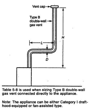
FIGURE G.1(a) TYPE B DOUBLE-WALL VENT SYSTEM SERVING A SINGLE APPLIANCE WITH A TYPE B DOUBLE-WALL VENT.
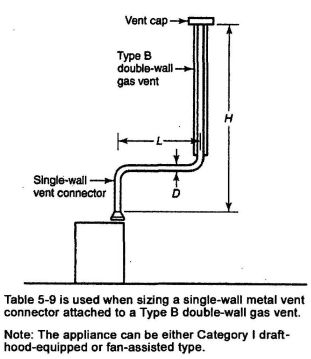
FIGURE G.1(b) TYPE B DOUBLE-WALL VENT SYSTEM SERVING A SINGLE APPLIANCE WITH A SINGLE-WALL METAL VENT CONNECTOR.
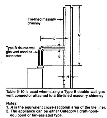
FIGURE G.1(c) VENT SYSTEM SERVING A SINGLE APPLIANCE WITH A MASONRY CHIMNEY AND A TYPE B DOUBLE-WALL VENT CONNECTOR.
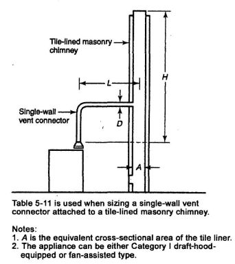
FIGURE G.1(d) VENT SYSTEM SERVING A SINGLE APPLIANCE USING A MASONRY CHIMNEY AND A SINGLE-WALL METAL VENT CONNECTOR.
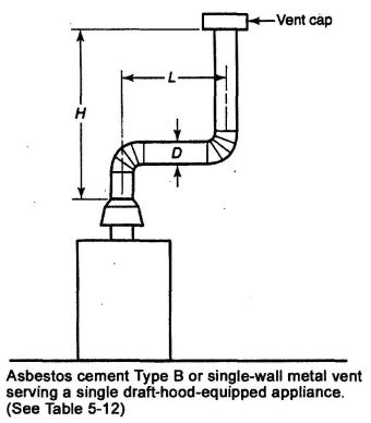
FIGURE G.1(e) ASBESTOS CEMENT TYPE B OR SINGLE-WALL METAL VENT SYSTEM SERVING A SINGLE DRAFT-HOOD-EQUIPPED APPLIANCE
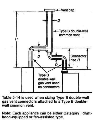
FIGURE G.1(f) VENT SYSTEM SERVING TWO OR MORE APPLIANCES WITH TYPE B DOUBLE-WALL VENT AND TYPE B DOUBLE-WALL VENT CONNECTORS
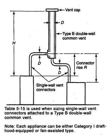
FIGURE G.1(g) VENT SYSTEM SERVING TWO OR MORE APPLIANCES WITH TYPE B DOUBLE-WALL VENT AND SINGLE-WALL METAL VENT CONNECTORS.
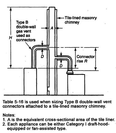
FIGURE G.1(h) MASONRY CHIMNEY SERVING TWO OR MORE APPLIANCES WITH TYPE B DOUBLE-WALL VENT CONNECTORS.
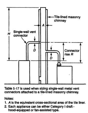
FIGURE G.1(i) MASONRY CHIMNEY SERVING TWO OR MORE APPLIANCES WITH SINGLE-WALL VENT CONNECTORS.
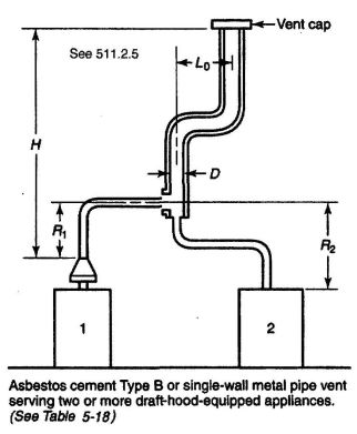
FIGURE G.1(j) ASBESTOS CEMENT TYPE B OR SINGLE-WALL METAL VENT SYSTEM SERVING TWO OR MORE DRAFT-HOOD-EQUIPPED APPLIANCES.
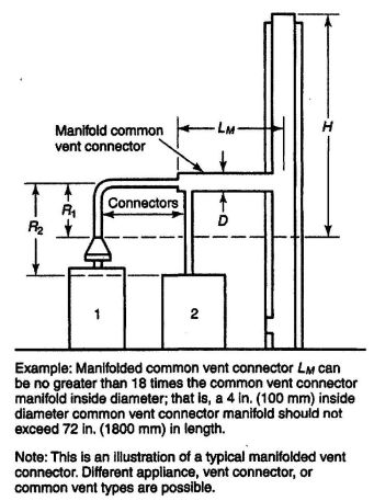
FIGURE G.1(k) USE OF MANIFOLDED COMMON VENT CONNECTOR.
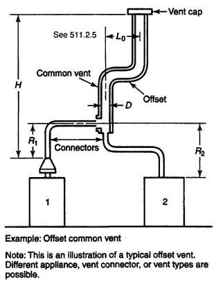
FIGURE G.1(l) USE OF OFFSET COMMON VENT.
G.1.1 Example 1: Single Draft-Hood-Equipped Appliance. An installer has 120,000-Btu/h input appliance with a five (5) inch diameter draft hood outlet that needs to be vented into a ten (10) foot high Type B vent system. What size vent should be used assuming (1) a five (5) foot lateral single-wall metal vent connector is used with two (2) 90 degree elbows or (2) a five (5) foot lateral single-wall metal vent connector is used with three (3) 90 degree elbows in the vent system? (See Figure G.1.1).
Solution
Table 5-9 should be used to solve this problem because single-wall metal vent connectors are being used with a Type B vent, as follows:
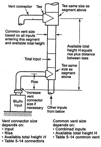
FIGURE G.1(m) MULTISTORY GAS VENT DESIGN PROCEDURE
FOR EACH SEGMENT OF SYSTEM
122,000 x 0.90 = 110,000 for five (5) inch vent
From Table 5-10, select six (6) inch vent.
186,000 x 0.90 = 167,000
This figure is exceeding the required 120,000. Therefore, use a six (6) inch vent and connector where three (3) elbows are used.
G.1.2. Example 2: Single Fan-Assisted Appliance. An installer has an 80,000 Btu/h input fan-assisted appliance that must be installed using ten (10) feet of lateral connector attached to a thirty (30) foot high Type B vent. Two (2) 90 degree elbows are needed for the installation. Can a single-wall metal vent connector be used for this application? See Figure G.1.2.
Solution
Table 5-9 refers to the use of single-wall metal vent connectors with Type B vent. In the first column find the row associated with a thirty (30) foot height and a ten (10) foot lateral. Read across this row, looking at the FAN Min and FAN Max columns, to find that a three (3) inch diameter single-wall metal vent connector is not recommended. Moving to the next larger
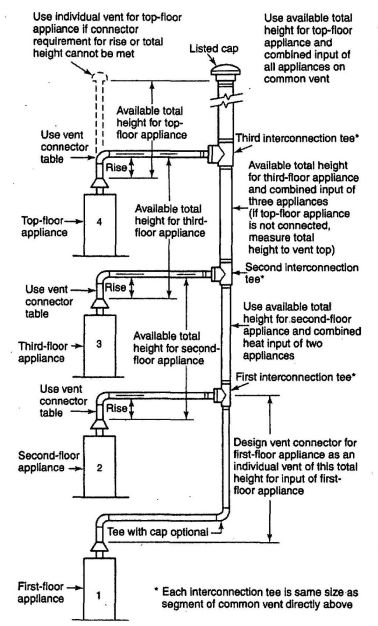
FIGURE G.1(n) PRINCIPLES OF DESIGN OF MULTISTORY VENTS USING VENT CONNECTOR AND COMMON VENT DESIGN TABLES.
size single-wall connector (four (4) inch), we find that a four (4) inch diameter single-wall metal connector has a recommended maximum vent capacity of 144,000 Btu/h. The 80,000 Btu/h fan-assisted appliance is outside this range, so the conclusion is that a single-wall metal connector could be used to vent the appliance. Table 5-9 shows the acceptable range of vent capacities for a four (4) inch vent with five (5) feet of lateral to be between 72,000 Btu/h and 157,000 Btu/h.
If the appliance cannot be moved closer to the vertical vent, then a Type B vent could be used as the connector material. In this case, Table 5-8 shows that, for a thirty (30) foot high vent with ten (10) feet of lateral, the acceptable range of vent capacities for a four (4) inch diameter vent attached to a fan-assisted appliance is between 37,000 Btu/h and 150,000 Btu/h.
G.1.3. Example 3: Interpolating Between Table Values. An installer has an 80,000 Btu/h input appliance with a four (4) inch diameter draft hood outlet that needs to be vented into a twelve (12) foot high Type B vent. The vent connector has a 5-foot lateral length and is also Type B vent. Can this appliance be vented using a four (4) inch diameter vent?
Solution
Table 5-8 is used in the case of an all Type B Vent system. However, since there is no entry in Table 5-8 for a height of twelve (12) feet, interpolation must be used. Read down the four (4) inch diameter. NAT Max column to the row associated with a ten (10) foot height and five (5) foot lateral to find the capacity value of 77,000 Btu/h. Read further down to the fifteen (15) foot height, five (5) foot lateral row to find the capacity value of 87,000 Btu/h. The difference between the fifteen (15) foot height capacity value and the ten (10) foot height capacity value is 10,000 Btu/h. The capacity for a vent system with a twelve (12) foot height is equal to the capacity for a ten (10) foot height plus two-fifths (⁄25) of the difference between the ten (10) foot and height plus two-fifths (25) for the difference between the ten (10) foot and fifteen (15) foot height values, or 77,000 +2/5 x 10,000 = 81,000 Btu/h. Therefore, a four (4) inch diameter vent can be used in the installation.
G.2 Examples Using Common Venting Tables.
G.2.1 Example 4: Common Venting Two Draft-Hood- Equipped Appliances. A 35,000-Btu/h water heater is to be common vented with a 150,000 Btu/h furnace, using a common vent with a total height of thirty (30) feet. The connector rise is two (2) feet for the water heater with a horizontal length of four (4) feet. The connector rise for the furnace is three (3) feet with a horizontal length of eight (8) feet. Assume single-wall metal connectors will be used with Type B vent. What size connectors and combined vent should be used in this installation?
See Figure G.2.1.
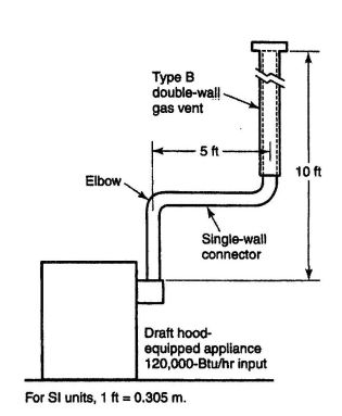
FIGURE G.1.1 SINGLE DRAFT HOOD-EQUIPPED APPLIANCE – EXAMPLE 1
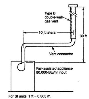
FIGURE G.1.2 SINGLE FAN-ASSISTED APPLIANCE – EXAMPLE 2
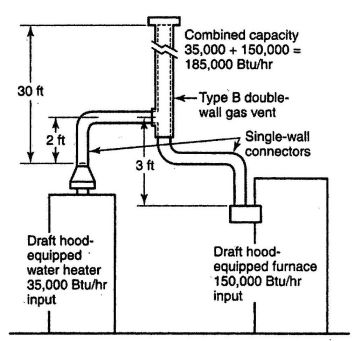
FIGURE G.2.1 COMMON VENTING TWO DRAFT HOOD-EQUIPPED APPLIANCES – EXAMPLE 4
Solution
Table 5-15 should be used to size single-wall metal vent connectors attached to Type B vertical vents. In the vent connector capacity portion of Table 5-15, find the row associated with a thirty (30) foot vent height. For a two (2) foot rise on the vent connector for the water heater, read the shaded columns for draft-hood-equipped appliances to find that a three (3) inch diameter vent connector has a capacity of 37,000 Btu/h. Therefore, a three (3) inch single-wall metal vent connector can be used with the water heater. For a draft-hood-equipped furnace with a three (3) foot rise, read across the appropriate row to find that a five (5) inch diameter vent connector has a maximum capacity of 120,000 Btu/h. (which is too small for the furnace), and a six (6) inch diameter vent connector has a maximum vent connector should be used with the 150,000 Btu/h furnace. Since both vent connector horizontal lengths are less than the maximum lengths listed in Table 5-8, the table values can be used without adjustments.
In the common vent capacity portion of Table 5-15, find the row associated with a thirty (30) foot vent height and read over to the NAT + NAT portion of the six (6) inch diameter column to find a maximum combined capacity of 257,000 Btu/h. Since the two (2) appliances total only 185,000 Btu/h, a six (6) inch common vent can be used.
G.2.2 Example 5(a): Common Venting a Draft-Hood-Equipped Water Heater with a Fan-Assisted Furnace into a Type B Vent. In this case, a 35,000-Btu/h input draft-hood-equipped water heater with a four (4) inch diameter draft hood outlet, two (2) feet of connector rise, and four (4) feet of horizontal length is to be common vented with a 100,000 Btu/h fan-assisted furnace with a four (4) inch diameter flue collar, three (3) feet of connector rise, and six (6) feet of horizontal length. The common vent consists of a thirty (30) foot height of Type B vent. What are the recommended vent diameters for each connector and the common vent? The installer would like to use a single-wall metal vent connector. See Figure G.2.2.
Solution (See Table 5-15)
Water Heater Vent Connector Diameter. Since the water heater vent connector horizontal length of four (4) feet is less than the maximum value listed in Table 5-15, the venting table values can be used without adjustment. Using the Vent Connector Capacity portion of Table 5-15, read down the Total Vent Height (H) column to thirty (30) feet and read across the two (2) feet Connector Rise (R) row to the first Btu/h rating in the NAT Max column that is equal to or exceeding the water heater input rating. The table shows that a three (3) inch vent connector has a maximum input rating of 37,000 Btu/h. Although this rating is exceeding the water heater input rating, a three (3) inch vent is exceeding the water heater input rating, a three (3) inch vent connector is prohibited by Section 511.1.1(5). A four (4) inch vent connector has a maximum input rating of 67,000 Btu/h and is equal to the draft hood outlet diameter. A four (4) inch vent connector is
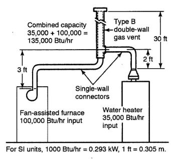
FIGURE G.2.2 COMMON VENTING A DRAFT HOOD-EQUIPPED WATER HEATER WITH A FAN-ASSISTED FURNACE INTO A TYPE B DOUBLE-WALL COMMON VENT–EXAMPLE 5(a).
| NOMINAL LINER SIZE (inch) | INSIDE DIMENSIONS OF LINER (inch) | INSIDE DIAMETER OR EQUIVALENT DIAMETER (inch) | EQUIVALENT AREA (inch2) |
|---|---|---|---|
| For SI units, 1 in. = 25.4 mm, 1 in.2 = 645 mm2. | |||
| Note: When liner sizes differ dimensionally from those shown in this table, equivalent diameters can be determined from published tables for square and rectangular ducts of equivalent carrying capacity or by other engineering methods. | |||
| 4 x 8 | 2½ x 6½ | 4.0 | 12.2 |
| 5.0 | 19.6 | ||
| 6.0 | 28.3 | ||
| 7.0 | 38.3 | ||
| 8 x 8 | 6¾ x 6¾ | 7.4 | 42.7 |
| 8.0 | 50.3 | ||
| 8 x 12 | 6½ x 10½ | 9.0 | 63.6 |
| 10.0 | 78.5 | ||
| 12 x 12 | 9¾ x 9¾ | 10.4 | 83.3 |
| 11.0 | 95.0 | ||
| 12 x 16 | 9½ x 13½ | 11.8 | 107.5 |
| 12.0 | 113.0 | ||
| 14.0 | 153.9 | ||
| 16 x 16 | 13¼ x 13¼ | 14.5 | 162.9 |
| 15.0 | 176.7 | ||
| 16 x 20 | 13 x 17 | 16.2 | 206.1 |
| 18.0 | 254.4 | ||
| 20 x 20 | 16¾ x 16¾ | 18.2 | 260.2 |
| 20.0 | 314.1 | ||
| 20 x 24 | 16½ x 20½ | 20.1 | 314.2 |
| 22.0 | 380.1 | ||
| 24 x 24 | 20¼ x 20¼ | 22.1 | 380.1 |
| 24.0 | 452.3 | ||
| 24 x 28 | 20¼ x 24¼ | 24.1 | 456.2 |
| 28 x 28 | 24¼ x 24¼ | 26.4 | 543.3 |
| 27.0 | 572.5 | ||
| 30 x 30 | 25½ x 25½ | 27.9 | 607.0 |
| 30 x 36 | 25½ x 31½ | 30.9 | 749.9 |
| 33.0 | 855.3 | ||
| 36 x 36 | 31½ x 31½ | 34.4 | 929.4 |
| 36.0 | 1017.9 | ||
selected. Since the water heater is equipped with a draft hood, there are no minimum input rating restrictions.
Furnace Vent Connector Diameter. Using the Vent Connector Capacity portion of Table 5-15, read down the Total Vent Height (H) column to thirty (30) feet and across the three (3) foot Connector Rise (R) row. Since the furnace has a fanassisted combustion system, find the first FAN Max column with a Btu⁄h rating exceeding the furnace input rating. The four (4) inch vent connector has a maximum input rating of 119,000 Btu⁄h and a minimum input rating of 85,000 Btu⁄h.
The 100,000-Btu⁄h furnace in this example falls within this range, so a four (4) inch connector is adequate. Since the furnace vent connector horizontal length of six (6) feet is less than the maximum value listed in Table 5-8, the venting table values can be used without adjustment. If the furnace had an input rating of 80,000 Btu⁄h then a Type B vent connector would be needed in order to meet the minimum capacity limit (See Table 5-14).
Common Vent Diameter. The total input to the common vent is 135,000 Btu⁄h. Using the Common Vent Capacity portion of Table 5-15, read down the Vent Height (H) column to thirty (30) feet and across this row to find the smallest vent diameter in the FAN + NAT column that has a Btu⁄h rating equal to or exceeding 135,000 Btu⁄h. The four (4) inch common vent has a capacity of 132,000 Btu⁄h and the five (5) inch common vent has a capacity of 202,000 Btu⁄h. Therefore, the five (5) inch common vent should be used in this example.
Summary: In this example, the installer can use of four (4) inch diameter, single-wall metal vent connector for the water heater and a four (4) inch diameter, single-wall metal vent connector for the furnace. The common vent should be a five (5) inch diameter Type B vent.
G.2.3 Example 5(b): Common Venting into an Interior Masonry Chimney. In this case, the water heater and fan-assisted furnace of Example 5(a) are to be common-vented into a claytile-lined masonry chimney with a thirty (30) foot height. The chimney is not exposed to the outdoors below the roof line. The internal dimensions of the clay tile liner are nominally eight (8) inches x twelve (12) inches. Assuming the same vent connector heights, laterals, and materials found in example 5(a), what are the recommended vent connector diameters, and is this an acceptable installation
Solution
Table 5-17 is used to size common venting installations involving single-wall connectors into masonry chimneys.
Water Heater Vent Connector Diameter. Using Table 517, Vent Connector Capacity, read down the Vent Height (H) column to thirty (30) feet, and read across the two (2) foot Connector Rise (R) row to the first Btu⁄h rating in the NAT Max column that is equal to or exceeding the water heater input rating. The table shows that a three (3) inch vent connector has a maximum input of only 31,000 Btu⁄h, while a four (4) inch vent connector has a maximum input of 57,000 Btu⁄h. A four (4) inch vent connector must therefore be used.
Furnace Vent Connector Diameter. Using the Vent Connector Capacity portion of Table 5-17, read down the total Vent Height (H) Column to thirty (30) feet and across the three (3) feet Connector Rise (R) row. Because the furnace has a fan-assisted combustion system, find the first FAN Max column with a Btu⁄h rating exceeding the furnace input rating. The four (4) inch vent connector has a maximum input rating of 127,000 Btu⁄h and a minimum input rating of 95,000 Btu⁄h. The 100,000 Btu⁄h furnace in this example falls within this range, so a four (4) inch connector is adequate.
Masonry Chimney. From Table G.2.3, the equivalent area for a nominal liner size of eight (8) inches x twelve (12) inches is sixty-three and six-tenths (63.6) of a square inch. Using Table 5-17, Common Vent Capacity, read down the FAN + NAT column under the Minimum Internal Area of Chimney value of sixty-three (63) to the row for thirty (30) foot height to find a capacity value of 739,000 Btu⁄h. The combined input rating of the furnace and water heater, 135,000 Btu⁄h, is less than the table value so this is an acceptable installation.
Section 511.1.8 requires the common vent area to not exceed seven (7) times the smallest listed appliance categorized vent area, flue collar area, or draft hood outlet area. Both appliances in this installation have four (4) inch diameter outlets. From Table G.2.3, the equivalent area for an inside diameter of four (4) inches in twelve and two-tenths (12.2) of a square inch. Seven (7) times twelve and two-tenths (12.2) equals eighty-five and four-tenths (85.4), which is exceeding sixtythree and six-tenths (63.6), so this configuration is acceptable.
G.2.4 Example 5(c): Common Venting into an Exterior Masonry Chimney. In this case, the water heater and fan-assisted furnace of Examples 5(a) and 5(b) are to be commonvented into an exterior masonry chimney. The chimney height, clay-tile-liner dimensions, and vent connector heights and laterals are the same as in Example 5(b). This system is being installed in Charlotte, North Carolina. Does this exterior masonry chimney need to be relined? If so, what corrugated metallic liner size is recommended? What vent connector diameters are recommended? See Table G.2.3 and Figure 5-14.
Solution
According to 511.2.17, Type B vent connectors are required to be used with exterior masonry chimneys. Use Table 5-21 and Table 5-22 to size FAN+NAT common venting installations involving Type-B double-wall connectors into exterior masonry chimneys.
The local 99 percent winter design temperature needed to use Table 5-21 and Table 5-22 to can be found in the ASHRAE Handbook– Fundamentals. For Charlotte, North carolina, this design temperature is 19°F (-7.22°C).
Chimney Liner Requirement. As in Example 5(b), use the sixty-three (63) square inch column of Table 5-21 to the thirty
(30) foot height row to find that the combined appliance maximum input is 747,000 Btu⁄h. The combined input rating of the appliance in this installation, 135,000 Btu⁄h, is less than the maximum value, so this criterion is satisfied. Table 5-22, at a 19°F (-7.22°C) design temperature, and at the same vent height and internal area used earlier, shows that the minimum allowable input rating of a space-heating appliance is 470,000 Btu⁄h. The furnace input rating of 100,000 Btu⁄h is less than this minimum value. So this criterion is not satisfied, and an alternative venting design needs to be used, such as a Type B vent shown in Example 5(a) or a listed chimney liner system shown in the rest of the example.
According to Section 511.2.19, Table 5-9 or Tables 5-14 or 5-15 are used for sizing corrugated metallic liners in masonry chimneys, with the maximum common vent capacities reduced by 20 percent. This example will be continued assuming Type B vent connectors.
Water Heater Vent Connector Diameter. Using Table 5-14 Connector Capacity, read down the total Vent Height (H) column to thirty (30) feet, and read across the two (2) foot Connector Rise (R) row to the first Btu⁄hour rating in the Nat Max column that is equal to or exceeding the water heater input rating. The table shows that a three (3) inch vent connector has a maximum capacity of 39,000 Btu⁄h. Although this rating is exceeding the water heater input rating, a three (3) inch vent connector is prohibited by Section 511.1.6. A four (4) inch vent connector has a maximum input rating of 70,000 Btu⁄h and is equal to the draft hood outlet diameter. A four (4) inch vent connector is selected.
Furnace Vent Connector Diameter. Using Table 5-14, Vent Connector Capacity, read down the total Vent Height (H) column to thirty (R) feet, and read across the three (3) foot Connector Rise (R) row to the first Btu⁄h rating in the FAN MAX column that is equal to or exceeding the furnace input rating. The 100,000 Btu⁄h furnace in this example falls within this range, so a four (4) inch connector is adequate.
Chimney Liner Diameter. The total input to the common vent is 135,000 Btu⁄h. Using the Common Vent Capacity portion of Table 5-14, read down the total Vent Height (H) column to thirty (30) feet and across this row to find the smallest vent diameter in the FAN + NAT column that has a Btu⁄h rating exceeding 135,000 Btu⁄h.The four (4) inch common vent has a capacity of 138,000 Btu⁄h. Reducing the maximum capacity by 20 percent (See 13.2.19) results in a maximum capacity for a four (4) inch corrugated liner of 110,000 Btu⁄h, less than the total input of 135,000 Btu⁄h. So a larger liner is needed. The five (5) inch common vent capacity listed in Table 5-14 is 210,000 Btu⁄h, and after reducing by 20 percent is 168,000 Btu⁄h. Therefore, a five (5) inch corrugated metal liner should be used in this example.
Single Wall Connectors. Once it has been established that relining the chimney is necessary, Type B double-wall vent connectors are not specifically required. This example could be redone using Table 5-15 for single-wall vent connectors. For this case, the vent connector and liner diameters would be the same as found for Type B double-wall connectors.
The following is originally from NFPA 54, National Fuel Gas Code, which contains additional reference.
Example of Combination of Indoor and Outdoor Combustion and Ventilation Opening Design.
J.1 Example of Combination Indoor and Outdoor Combustion Air Opening. Determine the required combination of indoor and outdoor combustion air opening sizes for the following appliance installation example.
Example Installation: A fan-assisted furnace and a draft-hood-equipped water heater with the following inputs are located in a fifteen (15) foot x thirty (30) foot basement with an eight (8) foot ceiling. No additional indoor spaces can be used to help meet the appliance combustion air needs.
Fan-Assisted Furnace Input: 100,000 Btu⁄h
Draft-Hood-Equipped Water Heater Input: 40,000 Btu⁄h
Solution
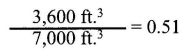
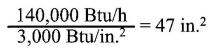
| APPLIANCE INPUT (Btu⁄h) | REQUIRED VOLUME (ft.3) |
|---|---|
| 507.4.1 See Figure 5-8 • 507.4.1(1) See Figure 5-9 and Figure 5-10 • | |
| 507.4.1(2) See Figure 5-11 • 507.4.2 See Figure 5-12 | |
| 5000 | 250 |
| 10 000 | 500 |
| 15 000 | 750 |
| 20 000 | 1000 |
| 25 000 | 1250 |
| 30 000 | 1500 |
| 35 000 | 1750 |
| 40 000 | 2000 |
| 45 000 | 2250 |
| 50 000 | 2500 |
| 55 000 | 2750 |
| 60 000 | 3000 |
| 65 000 | 3250 |
| 70 000 | 3500 |
| 75 000 | 3750 |
| 80 000 | 4000 |
| 85 000 | 4250 |
| 90 000 | 4500 |
| 95 000 | 4750 |
| 100 000 | 5000 |
| 105 000 | 5250 |
| 110 000 | 5500 |
| 115 000 | 5750 |
| 120 000 | 6000 |
| 125 000 | 6250 |
| 130 000 | 6500 |
| 135 000 | 6750 |
| 140 000 | 7000 |
| 145 000 | 7250 |
| 150 000 | 7500 |
| 160 000 | 8000 |
| 170 000 | 8500 |
| 180 000 | 9000 |
| 190 000 | 9500 |
| 200 000 | 10 000 |
| 210 000 | 10 500 |
| 220 000 | 11 000 |
| 230 000 | 11 500 |
| 240 000 | 12 000 |
| 250 000 | 12 500 |
| 260 000 | 13 000 |
| 270 000 | 13 500 |
| 280 000 | 14 000 |
| 290 000 | 14 500 |
| 300 000 | 15 000 |
| Adopting Agency | BSC | SFM | HCD | DSA | OSHPD | CSA | DPH | AGR | DWR | CA | |||||||
|---|---|---|---|---|---|---|---|---|---|---|---|---|---|---|---|---|---|
| 1 | 2 | 1/AC | AC | SS | SS/CC | 1 | 2 | 3 | 4 | ||||||||
| The state agency does not adopt sections identified by the following symbol:† | |||||||||||||||||
| Adopt Entire Chapter | |||||||||||||||||
| Adopt Entire Chapter as amended (amended sections listed below) | X | X | X | X | X | X | X | X | X | X | |||||||
| Adopt only those sections that are listed below | X | X | X | ||||||||||||||
| Chapter/Section | |||||||||||||||||
| 601.1 | X | X | X | ||||||||||||||
| 601.2.2 | X | X | |||||||||||||||
| 601.4 | X | X | |||||||||||||||
| 601.5 | X | ||||||||||||||||
| 601.5.1 | X | ||||||||||||||||
| 601.5.2 | X | ||||||||||||||||
| 601.5.3 | X | ||||||||||||||||
| 601.6 | X | ||||||||||||||||
| 601.7 | X | ||||||||||||||||
| 601.8 | X | ||||||||||||||||
| 601.9 | X | ||||||||||||||||
| 603.4.11 | X | X | |||||||||||||||
| 603.4.16, Note | X | ||||||||||||||||
| 604.1 Exc. 1 | X | X | X | X | |||||||||||||
| 604.1 Exc. 2 | X | X | X | X | |||||||||||||
| 604.1 Exc. 3 | X | X | X | X | |||||||||||||
| 604.1 Exc. 4 | X | X | X | X | |||||||||||||
| 604.1 Exc. 5 | X | X | X | X | |||||||||||||
| 604.1.1 | X | X | |||||||||||||||
| 604.10 | X | X | X | X | X | X | X | ||||||||||
| 604.11 & subsections | X | X | X | X | |||||||||||||
| 604.13 | X | X | X | ||||||||||||||
| 604.13 Exc. | X | X | X | X | |||||||||||||
| 604.13.1 | X | X | X | ||||||||||||||
| 604.13.1 Exc. | X | X | X | X | |||||||||||||
| 604.13.2 | X | X | X | ||||||||||||||
| 604.13.2 Exc. | X | X | X | X | |||||||||||||
| Table 6-4 | X | X | X | X | X | X | X | ||||||||||
| 605.8 | X | X | X | X | |||||||||||||
| 609.9 | X | X | X | X | |||||||||||||
| 609.10 | † | † | |||||||||||||||
| Table 6-5 | X | ||||||||||||||||
| 609.11 | X | X | X | ||||||||||||||
| 612.0 & subsections | X | X | X | X | |||||||||||||
| Table 6-9 | X | X | X | X | |||||||||||||
| 613.0 & subsections | X | X | X | X | |||||||||||||
| 614.0 | X | X | X | X | |||||||||||||
| 614.1 | X | X | X | X | |||||||||||||
| 614.2 | X | X | X | X | |||||||||||||
| 614.3 | X | X | X | X | |||||||||||||
| 614.4 | X | ||||||||||||||||
601.0 Hot and Cold Water Required.
601.1 Except where not deemed necessary for safety or sanitation by the Authority Having Jurisdiction, each plumbing fixture shall be provided with an adequate supply of potable running water piped thereto in an approved manner, so arranged as to flush and keep it in a clean and sanitary condition without danger of backflow or cross-connection. Water closets and urinals shall be flushed by means of an approved flush tank or flushometer valve.
Exceptions:
- [HCD 1, HCD 2, and DWR] Listed fixtures that do not require water for their operation and are not connected to the water supply.
- [HCD 1 & HCD 2] For limited-density owner-built rural dwellings, potable water shall be available to the dwelling site, although such water need not be pressurized. Where water is not piped from a well, spring, cistern, or other source, there shall be a minimum reserve of 50 gallons (189 L) of potable water available. Where water delivery is pressurized, piping shall be installed in accordance with the provisions of this chapter.
- [HCD 1 & HCD 2] Where deemed not necessary for safety or sanitation by the Enforcing Agency.
- [HCD 1 & HCD 2] Recycled water or treated graywater may be allowed as specified in Chapter 16 Part II of this code.
- [DWR] Where a public agency requires a building to use recycled water to flush water closets and urinals in accordance with California Water Code 13554.
In occupancies where plumbing fixtures are installed for private use, hot water shall be required for bathing, washing, laundry, cooking purposes, dishwashing or maintenance. In occupancies where plumbing fixtures are installed for public use, hot water shall be required for bathing and washing purposes. This requirement shall not supersede the requirements for individual temperature control limitations for public lavatories, bathtubs, whirlpool bathtubs and shower control valves.
601.2 Identification of a Potable and Non-potable Water System. In buildings where potable water and non-potable water systems are installed, each system shall be clearly identified in accordance with Sections 601.2.1 through 601.2.4
601.2.1 Potable Water. Green background with white lettering.
601.2.2 Color and Information. Each system shall be identified with a colored pipe or band and coded with paints, wraps and materials compatible with the piping.
Except as required in Sections 1610.0 and 1617.0, non-potable water systems shall have a yellow background with black uppercase lettering, with the words “CAUTION: NON-POTABLE WATER, DO NOT DRINK.” Each non-potable system shall be identified to designate the liquid being conveyed, and the direction of normal flow shall be clearly shown. The minimum size of the letters and length of the color field shall conform to Table 6-1 [HCD 1 & HCD 2] An international symbol of a glass in a circle with a slash through it shall be provided similar to that shown in Figure 6-1 for all non-portable water systems.
The background color and required information shall be indicated every twenty (20) feet (6,096 mm) but not less than once per room, and shall be visible from the floor level.
| OUTSIDE DIAMETER OF PIPE OR COVERING | MINIMUM LENGTH OF COLOR FIELD | MINIMUM SIZE OF LETTERS | |||
|---|---|---|---|---|---|
| inches | (mm) | inches | (mm) | inches | (mm) |
| ½ to 1¼ | (15 to 32) | 8 | (203) | ½ | (12.7) |
| 1½ to 2 | (40 to 50) | 8 | (203) | ¾ | (19.1) |
| 2½ to 6 | (65 to 150) | 12 | (305) | 1¼ | (32) |
| 8 to 10 | (200 to 250) | 24 | (610) | 2½ | (64) |
| Over 10 | (Over 250) | 32 | (813) | 3½ | (89) |
601.2.3 Fixtures. Where vacuum breakers or backflow preventers are installed with fixtures listed in Table 14—1, identification of the discharge side shall be permitted to be omitted.
601.2.4 Outlets. Each outlet on the non-potable water line that is used for special purposes shall be posted with black uppercase lettering as follows: “CAUTION: NON-POTABLE WATER, DO NOT DRINK.”

FIGURE 6-1
INTERNATIONAL SYMBOL
601.3 Faucets and diverters shall be connected to the water distribution system so that hot water corresponds to the left side of the fittings.
601.4 [HCD 1 & HCD 2] All sources for drinking water shall be maintained in a clean and sanitary condition. Drinking fountains and portable water dispensers shall not be located in toilet rooms.
601.5 [CA] Schools of Cosmetology and Cosmetological Establishments.
| DEGREE OF HAZARD | ||||||
|---|---|---|---|---|---|---|
| DEVICE, ASSEMBLY, OR METHOD1 | APPLICABLE STANDARDS | POLLUTION (LOW HAZARD) | CONTAMINATION (HIGH HAZARD) | INSTALLATION2,3 | ||
| BACK- SIPHONAGE | BACK-PRESSURE | BACK-SIPHONAGE | BACK-PRESSURE | |||
| 1 See description of devices and assemblies in this chapter. | ||||||
| 2 Installation in pit or vault requires previous approval by the Authority Having Jurisdiction. | ||||||
| 3 Refer to general and specific requirement for installation. | ||||||
| 4 Not to be subjected to operating pressure for more than twelve (12) hours in any twenty-four (24) hour period. | ||||||
| 5 For deck-mounted and equipment-mounted vacuum breaker, see Section 603.4.15. | ||||||
| Airgap | ASME A112.1.2 | X | X | See Table 6-3 in this chapter. | ||
| Air gap fittings for use with plumbing fixtures, appli-ances and appurtenances | ASME A112.1.3 | X | Air gap fitting is a device with an internal air gap and typical installation includes plumbing fixtures, appli-ances and appurtenances. The critical level shall not be installed below the flood level rim. | |||
| Atmospheric-type vacuum breaker (consists of a body, checking member and atmospheric port) | ASSE 1001 or CSA B64.1.1 | X | X | Upright position. No value downstream. Minimum of six (6) inches (152 mm) or listed distance above all downstream piping and flood-level rim of receptor.4,5 | ||
| Antisiphon fill valve (ball-cocks) for gravity water closet flush tanks and urinal tanks | ASSE 1002 or CSA B 125.3 | X | X | Installation on gravity water closet flush tank and urinal tanks with the fill valve installed with the critical level not less than 1 inch above the opening of the overflow pipe.4,5 | ||
| Vacuum breaker wall hydrants, hose bibbs, frost resistant, automatic draining type | ASSE 1019 or CSA B 64.2.1.1 | X | X | Installation includes wall hydrants and hose bibbs. Such devices are not for use under continuous pressure conditions (means of shut-off downstream of device is prohibited).4,5 | ||
| Backflow preventer for Carbonated Beverage Dispensers (two independent check valves with a vent to the atmosphere) | ASSE 1022 | X | Installation includes carbonated beverage machines or dispensers. These devices operate under intermittent or continuous pressure conditions. | |||
| Spill-Resistant Pressure- Type Backflow Prevention Assembly (single check valve with air inlet vent and means of field testing) | ASSE 1056 | X | X | Upright position. Minimum of six (6) inches (152 mm) or listed distance above all downstream piping and flood-level rim of receptor.5 | ||
| Double Check Valve Back-flow Prevention Assem-bly (two independent check valves and means of field testing) | ASSE 1015; AWWA C510; CSA B 64.5 or CSA B 64.5.1 | X | X | Horizontal unless otherwise listed. Requires one (1) foot (305 mm) clearance at bottom for maintenance. May need platform/ladder for test and repair. Does not discharge water. | ||
| ASSE 1048 | X | X | Horizontal unless otherwise listed. Requires one (1) foot (305 mm) clearance at bottom for maintenance. May need platform/ladder for test and repair. Does not discharge water. Installation includes a fire protection system and is designed to operate under continuous pressure conditions. | |||
| Pressure Vacuum Breaker Backflow Prevention Assembly (loaded air inlet valve, internally loaded check valve and means of field testing) | ASSE 1020 or CSA B 64.1.2 | X | X | Upright position. May have valves downstream. Minimum of twelve (12) inches (305 mm) above all downstream piping and flood level rim of receptor. May discharge water. | ||
| Reduced Pressure Principle Backflow Prevention Assembly (two independently acting loaded check valves, a pressure relief valve and means of field testing) | ASSE 1047 | X | X | X | X | Horizontal unless otherwise listed. Requires one (1) foot (305 mm) minimum clearance at bottom for maintenance. May need platform/ladder for test and repair. May discharge water. Installation includes a fire protection system and is designed to operate under continuous pressure conditions. |
| ASSE 1013; AWWA C511; CSA B 64.4 or CSA B 64.4.1 | X | X | X | X | Horizontal unless otherwise listed. Requires one (1) foot (305 mm) minimum clearance at bottom for maintenance. May need platform/ladder for test and repair. May discharge water. | |
601.5.1 Hot-and Cold running Water. At least one sink with hot-and cold-running water shall be provided in each work area or workroom where hairdressing is performed in each school and establishment.
601.5.2 Handwashing Facilities. Each school and establishment shall provide adequate handwashing facilities, including hot-and cold-running water, located within or adjacent to the toilet room or rooms in accordance with Table 4-1.
601.5.3 Drinking Water. Each school and establishment shall supply potable drinking water convenient to students, patrons and employees. Approved sanitary drinking fountains shall be installed and so regulated that a jet of at least 2 inches (51 mm) shall be constantly available.
601.6 [AGR] Meat and Poultry Processing Plants. Except as provided in Section 601.6.4, the water supply shall be ample and potable, with adequate pressure and facilities for its distribution in the plant, and its protection against contamination and pollution.
Note: A water report, issued under the authority of the state health agency, certifying to the potability of the water supply, shall be obtained by the applicant and furnished to the administrator whenever such report is required by the administrator.
601.6.1 A supply of hot water shall be available.
601.6.2 Hose connections with steam and water-mixing valves or hot-water hose connections shall be provided at locations throughout the plant.
601.6.3 The refuse rooms shall be provided with facilities for washing refuse cans and other equipment in the rooms.
601.6.4 Non-potable water is permitted only in those parts of official plants where no product is handled or prepared, and then only for limited purposes, such as on condensers not connected with the potable water supply, in vapor lines serving inedible product rendering tanks, and in sewer lines for moving heavy solids in the sewage.
In all cases, non-potable water lines shall be clearly identified and shall not be cross connected with the potable water supply.
Exception: Cross connection is permitted if this is necessary for fire protection and such connection is of a type with a break to ensure against accidental contamination, and to be approved by local authorities and by the Department.
601.6.5 Equipment using potable water shall be so installed as to prevent back-siphonage into the potable water system.
601.6.6 All pipelines, reservoirs, tanks, cooling towers, and like equipment employed in handling reused water shall be constructed and installed so as to facilitate their cleaning and inspection.
601.6.7 Hot water of such temperature as to accomplish a through cleanup shall be delivered under pressure to outlets.
601.6.7.1 An ample supply of water at not less than 180°F (82°C) shall be available when used for sanitizing purposes.
601.6.8 Pens, alleys, and runways shall have hose connections for cleanup purposes.
601.7 [AGR] Collection Centers and Facilities.
601.7.1 The water supply shall be ample with facilities for its distribution. An ample supply of water at not less than 180°F (82°C), or other suitable method.
601.7.2 The vehicle cleaning and sanitizing area shall be provided with adequate line steam, producing a temperature of at least 180°F (82°C), or other suitable method.
601.7.3 Hose connections with steam and water-mixing valves of hot-and cold-water hose connections shall be provided at locations throughout the building and at unloading and vehicle cleaning slabs.
| FIXTURES | WHEN NOT AFFECTED BY SIDE WALLS1 | WHEN AFFECTED BY SIDEWALLS2 | ||
|---|---|---|---|---|
| Inches | (mm) | Inches | (mm) | |
| 1 Sidewalls, ribs, or similar obstructions do not affect airgaps when spaced from the inside edge of the spout opening a distance exceeding three (3) times the diameter of the effective opening for a single wall, or a distance exceeding four (4) times the effective opening for two (2) intersecting walls. | ||||
| 2 Vertical walls, ribs, or similar obstructions extending from the water surface to or above the horizontal plane of the spout opening other than specified in Note 1 above. The effect of three (3) or more such vertical walls or ribs has not been determined. In such cases, the airgap shall be measured from the top of the wall. | ||||
| 3 The effective opening shall be the minimum cross-sectional area at the seat of the control valve or the supply pipe or tubing that feeds the device or outlet. If two (2) or more lines supply one outlet, the effective opening shall be the sum of the cross-sectional areas of the individual supply lines or the area of the single outlet, whichever is smaller. | ||||
| 4 Airgaps less than one (1) inch (25.4 mm) shall be approved only as a permanent part of a listed assembly that has been tested under actual backflow conditions with vacuums of zero (0) to twenty-five (25) inches (635 mm) of mercury. | ||||
| Effective openings3 not greater than one-half (½) inch (12.7 mm) in diameter | 1 | (25.4) | 1½ | (38) |
| Effective openings3 not greater than three-quarters (¾) inch (19.1 mm) in diameter | 1½ | (38) | 2¼ | (57) |
| Effective openings3 not greater than one (1) inch (25.4 mm) in diameter | 2 | (51) | 3 | (76) |
| Effective openings3 greater than one (1) inch (25.4 mm) in diameter | Two (2) times diameter of effective opening | Three (3) times diameter of effective opening | ||
601.8 [AGR] Renderers. This area shall be provided with live steam or other method of sanitizing vehicles.
601.9 [AGR] Horse Meat and Pet Food Establishments.
601.9.1 The water supply shall be ample, clean, and potable, with facilities for its distribution in the plant, and its protection against contamination and pollution.
601.9.1.1 Equipment using potable water shall be so installed as to prevent back-siphonage into the potable water system.
601.9.1.2 Non-potable water is permitted only in those parts of official plants where no edible product is handled or prepared, and then only for limited purposes, such as on ammonia condensers not connected with the potable water supply, in vapor lines serving inedible product rendering tanks, in connection with equipment used for washing and washing inedible products preparatory to tanking, and in sewer lines for moving heavy solids in sewage. In all cases, non-potable water lines shall be clearly identified and shall not be cross connected with the potable water supply.
Exception: Cross connection is permitted if this is necessary for fire protection, and such connection is of a type with a break to ensure against accidental contamination, and is approved by local authorities or by the Department.
601.9.2 All pipelines, reservoirs, tanks, cooling towers, and like equipment employed in handling reused water shall be constructed and installed so as to facilitate their cleaning and inspection.
601.9.3 Hot water for cleaning rooms and equipment shall be delivered under pressure to outlets and shall be of such temperature as to accomplish a thorough cleanup.
601.9.3.1 An ample supply of water at not less than 180°F (82°C) shall be available when used for sanitizing purposes.
601.9.4 Pens, alleys, and runways shall have hose connections for cleanup purposes.
602.0 Unlawful Connections.
602.1 No installation of potable water supply piping or part thereof shall be made in such a manner that it will be possible for used, unclean, polluted, or contaminated water, mixtures, or substances to enter any portion of such piping from any tank, receptor, equipment, or plumbing fixture by reason of back-siphonage, suction, or any other cause, either during normal use and operation thereof, or when any such tank, receptor, equipment, or plumbing fixture is flooded or subject to pressure exceeding the operating pressure in the hot or cold water piping.
602.2 No person shall make a connection or allow one (1) to exist between pipes or conduits carrying domestic water supplied by any public or private water service system, and any pipes, conduits, or fixtures containing or carrying water from any other source or containing or carrying water that has been used for any purpose whatsoever, or any piping carrying chemicals, liquids, gases, or any substances whatsoever, unless there is provided a backflow prevention device approved for the potential hazard and maintained in accordance with this code. Each point of use shall be separately protected when potential cross-contamination of individual units exists.
602.3 No plumbing fixture, device, or construction shall be installed or maintained or shall be connected to any domestic water supply when such installation or connection provides a possibility of polluting such water supply or cross-connection between a distributing system of water for drinking and domestic purposes and water that becomes contaminated by such plumbing fixture, device, or construction unless there is provided a backflow prevention device approved for the potential hazard.
602.4 No water piping supplied by any private water supply system shall be connected to any other source of supply with out the approval of the Authority Having Jurisdiction, Health Department, or other department having jurisdiction.
603.0 Cross-Connection Control.
Cross-connection control shall be provided in accordance with the provisions of this chapter.
No person shall install any water-operated equipment or mechanism, or use any water-treating chemical or substance, if it is fond that such equipment, mechanism, chemical, or substance causes pollution or contamination of the domestic water supply. Such equipment or mechanism shall be permitted only when equipped with an approved backflow prevention device or assembly.
603.1 Approval of Devices or Assemblies. Before any device or assembly is installed for the prevention of backflow, it shall have first been approved by the Authority Having Jurisdiction. Devices or assemblies shall be tested for conformity with recognized standards or other standards acceptable to the Authority Having Jurisdiction. Backflow prevention devices and assemblies shall comply with Table 6–2, except for specific applications and provisions as stated in Sections 603.4 through 603.4.22.
Devices or assemblies installed in a potable water supply system for protection against backflow shall be maintained in good working condition by the person or persons having control of such devices or assemblies. Such devices or assemblies shall be tested at the time of installation, repair, or relocation and not less than on an annual schedule thereafter, or more often when required by the Authority Having Jurisdiction. If found to be defective or inoperative, the device or assembly shall be repaired or replaced. No device or assembly shall be removed from use or relocated or other device or assembly substituted, without the approval of the Authority Having Jurisdiction.
Testing shall be performed by a certified backflow assembly tester.
603.2 Backflow Prevention Devices, Assemblies, and Methods.
603.2.1 Airgap. The minimum airgap to afford backflow protection shall be in accordance with Table 6-3.
603.2.2 Atmospheric Vacuum Breaker (AVB). An atmospheric vacuum breaker consists of a body, a checking member, and an atmospheric port.
603.2.3 Hose Connection Backflow Preventer. A hose connection backflow preventer consists of two (2) independent check valves with an independent atmospheric vent between and a means of field testing and draining.
603.2.4 Double Check Valve Backflow Prevention Assembly (DC). A double check valve backflow prevention assembly consists of two (2) independently acting internally loaded check valves, four (4) properly located test cocks, and two (2) isolation valves.
603.2.5 Pressure Vacuum Breaker Backflow Prevention Assembly (PVB). A pressure vacuum breaker backflow prevention assembly consists of a loaded air inlet valve, an internally loaded check valve, two (2) properly located test cocks, and two (2) isolation valves. This device shall be installed indoors only if provisions for spillage are provided.
603.2.6 Pressure Vacuum Breaker Spill-Resistant-Type Backflow Prevention Assembly (SVB). A pressure-type vacuum breaker backflow prevention assembly consists of one (1) check valve force-loaded closed and an air inlet vent valve force-loaded open to atmosphere, positioned downstream of the check valve, and located between and including two (2) tightly closing shutoff valves and test cocks.
603.2.7 Reduced-Pressure Principle Backflow Prevention Assembly (RP). A reduced-pressure principle backflow prevention assembly consists of two (2) independently acting internally loaded check valves, a differential pressure-relief valve, four (4) properly located test cocks, and two (2) isolation valves.
603.3 General Requirements.
603.3.1 Assemblies shall conform to listed standards and be acceptable to the Authority Having Jurisdiction, with Jurisdiction over the selection and installation of backflow prevention assemblies.
603.3.2 Where more than one (1) backflow prevention valve is installed on a single premise, and the valves are installed in one (1) location, each separate valve shall be permanently identified by the permittee in a manner satisfactory to the Authority Having Jurisdiction.
603.3.3 The premise owner or responsible person shall have the backflow prevention assembly tested by a certified backflow assembly tester at the time of installation, repair, or relocation and not less than on an annual schedule thereafter, or more often when required by the Authority Having Jurisdiction. The periodic testing shall be performed in accordance with the procedures referenced in Table 14-1 by a tester qualified in accordance with those standards.
603.3.4 Access and clearance shall be provided for the required testing, maintenance, and repair. Access and clearance shall require a minimum of one (1) foot (305 mm) between the lowest portion of the assembly and grade floor, or platform. Installations elevated exceeding five (5) feet (1,524 mm) above the floor or grade shall be provided with a permanent platform capable of supporting a tester or maintenance person.
603.3.5 Direct connections between potable water piping and sewer-connected wastes shall not be permitted to exist under any condition with or without backflow protection. Where potable water is discharged to the drainage system, it shall be by means of an approved airgap of two (2) pipe diameters of the supply inlet, but in no case shall the gap be less than one (1) inch (25.4 mm). Connection shall be permitted to be made to the inlet side of a trap provided that an approved vacuum breaker is installed not less than six (6) inches (152 mm), or the distance according to the device's listing, above the flood-level rim of such trapped fixture, so that at no time will any such device be subjected to any back-pressure.
603.3.6 Backflow preventers for hot water exceeding 110°F (43.3°C) shall be a type designed to operate at temperatures exceeding 110°F (43.3°C) without rendering any portion of the assembly inoperative.
603.3.7 Fixtures, appliances, or appurtenances with integral backflow preventers or integral airgaps manufactured as a unit shall be installed in accordance with their listing requirements and the manufacturer's instructions.
603.3.8 In cold climate areas, backflow assemblies and devices shall be protected from freezing with an outdoor enclosure or by a method acceptable to the Authority Having Jurisdiction.
603.3.9 Drain lines serving backflow devices or assemblies shall be sized in accordance with the discharge rates of the manufacturer's flow charts of such devices or assemblies.
603.3.10 Design and Installation of Plumbing Fixtures. Plumbing fixtures shall be installed such that fixture fittings, complying with the backflow prevention requirements of ASME A112.18.1/CSA B125.1, Standard for Plumbing Supply Fittings, do not have these requirements compromised by the designated fixture fitting mounting surface.
603.4 Specific Requirements.
603.4.1 Water closet and urinal flushometer valves shall be equipped with an atmospheric vacuum breaker. The vacuum breaker shall be installed on the discharge side of the flushometer valve with the critical level not less than six (6) inches (152 mm), or the distance according to its listing, above the overflow rim of a water closet bowl or the highest part of a urinal.
603.4.2 Water closet and urinal tanks shall be equipped with a ballcock. The ballcock shall be installed with the critical level not less than one (1) inch (25.4 mm) above the full opening of the overflow pipe. In cases where the ballcock has no hush tube, the bottom of the water supply inlet shall be installed one (1) inch (25.4 mm) above the full opening of the overflow pipe.
603.4.3 Water closet flushometer tanks shall be protected against backflow by an approved backflow prevention assembly, device, or method.
603.4.4 Heat Exchangers.
603.4.4.1 Heat exchangers used for heat transfer, heat recovery, or solar heating shall protect the potable water system from being contaminated by the heat-transfer medium. Single-wall heat exchangers used in indirect-fired water heaters shall meet the requirements of Section 506.4.2. Double-wall heat exchangers shall separate the potable water from the heat-transfer medium by providing a space between the two (2) walls that are vented to the atmosphere.
603.4.5 Water supply inlets to tanks, vats, sumps, swimming pools, and other receptors shall be protected by one of the following means:
603.4.6 Protection from Lawn Sprinklers and Irrigation Systems.
603.4.6.1 Potable water supplies to systems having no pumps or connections for pumping equipment, and no chemical injection or provisions for chemical injection, shall be protected from backflow by one of the following devices:
603.4.6.2 Where sprinkler and irrigation systems have pumps, connections for pumping equipment, or auxiliary air tanks, or are otherwise capable of creating back-pressure, the potable water supply shall be protected by the following type of device if the backflow device is located upstream from the source of back-pressure:
603.4.6.3 Where systems have a backflow device installed downstream from a potable water supply pump or a potable water supply pump connection, the device shall be one of the following:
603.4.6.4 Where systems include a chemical injector or any provisions for chemical injection, the potable water supply shall be protected by the following:
603.4.7 Potable water outlets with hose attachments, other than water heater drains, boiler drains, and clothes washer connections, shall be protected by a nonremovable hose-bibb-type backflow preventer, a nonremovable hose bibb-type vacuum breaker, or by an atmospheric vacuum breaker installed not less than six (6) inches (152 mm) above the highest point of usage located on the discharge side of the last valve. In climates where freezing temperatures occur, a listed self-draining frost-proof hose bibb with an integral backflow preventer or vacuum breaker shall be used.
603.4.8 Water-cooled compressors, degreasers, or any other water-cooled equipment shall be protected by a backflow preventer installed in accordance with the requirements of this chapter.
Note: Water-cooled equipment that produces back-pressure shall be equipped with the appropriate protection.
603.4.9 Water inlets to water-supplied aspirators shall be equipped with a vacuum breaker installed in accordance with its listing requirements and this chapter. The discharge shall drain through an airgap. When the tailpiece of a fixture to receive the discharge of an aspirator is used, the airgap shall be located above the flood-level rim of the fixture.
603.4.10 Potable water makeup connections to steam or hot water boilers shall be provided with a listed backflow protection assembly.
603.4.11 Non-potable Water Piping. In cases where it is impractical to correct individual cross-connections on the domestic waterline, the line supplying such outlets shall be considered a non-potable water line. No drinking or domestic water outlets shall be connected to the non-potable waterline. Whenever possible, portions of the non-potable waterline shall be exposed, and exposed portions shall be properly identified in a manner satisfactory to the Authority Having Jurisdiction. Each outlet on the non-potable waterline that is permitted to be used for drinking or domestic purposes shall be posted: “CAUTION: NON-POTABLE WATER, DO NOT DRINK.” [HCD 1 & HCD 2] An international symbol of a glass in a circle with a slash through it shall be provided similar to that shown in Figure 6-1.
603.4.12 Potable water supply to carbonators shall be protected by either an airgap or a vented backflow preventer for carbonated beverage dispensers installed within the carbonated beverage dispenser. The carbonated beverage dispenser shall bear the label of an approved testing agency, certifying and attesting that such equipment has been tested and inspected and meets the requirements of the approved applicable standard. Carbonated beverage dispensers without an approved internal airgap or vented
backflow preventer for carbonated beverage dispensers and carbonated beverage dispensing systems shall have the water supply protected with a vented backflow preventer for carbonated beverage dispensers.
603.4.13 Water Treatment Units. Reverse osmosis drinking water treatment units shall meet the requirements of the applicable standards referenced in Table 14-1. Waste or discharge from reverse osmosis or other types of water treatment units shall enter the drainage system through an airgap.
603.4.14 Backflow preventers shall not be located in any area containing fumes that are toxic, poisonous, or corrosive.
603.4.15 Deck-mounted or equipment-mounted vacuum breakers shall be installed in accordance with their listing and the manufacturer's instructions, with the critical level not less than one (1) inch (25.4 mm) above the flood-level rim.
603.4.16 Protection from Fire Systems.
Note: Fire Protection Systems has not been adopted by the State Fire Marshal. This section cannot be adopted or enforced pursuant to California Health and Safety Code 13114.7(a), which is being cited for reference.
California Health and Safety Code 13114.7
603.4.17 Special Equipment, Water Supply Protection. Vacuum breakers for washer-hose bedpans shall be located not less than five (5) feet (1,524 mm) above the floor. Hose connections in health care or laboratory areas shall be not less than six (6) feet (1,829 mm) above the floor.
603.4.18 Portable cleaning equipment, dental vacuum pumps, and chemical dispensers shall be protected from backflow by an airgap, an atmospheric vacuum breaker, a spill-resistant vacuum breaker, or a reduced pressure principle backflow preventer.
603.4.19 Combination stop-and-waste valves or cocks shall not be installed underground.
603.4.20 Pure Water Process Systems. The water supply to a pure water process system, such as dialysis water systems, semiconductor washing systems, and similar process piping systems, shall be protected from back-pressure and back-siphonage by a reduced-pressure principle backflow preventer.
603.4.20.1 Dialysis Water Systems. The individual connections of the dialysis related equipment to the dialysis pure water system shall not require additional backflow protection.
603.4.21 Plumbing Fixture Fittings. Plumbing fixture fittings with integral backflow protection shall comply with ASME A112.18.1/CSA B 125.1, Standard for Plumbing Supply Fittings.
603.4.22 Potable water supply to swimming pools, spas, and hot tubs shall be protected by an airgap or a reduced pressure principle backflow preventer in accordance with the following:
604.0 Materials.
604.1 Pipe, tube, and fittings carrying water used in potable water systems intended to supply drinking water shall meet the requirements of NSF 61, Standard for Drinking Water System Components, as found in Table 14-1. Materials used in the water supply system, except valves and similar devices, shall be of a like material, except where otherwise approved by the Authority Having Jurisdiction.
Materials for building water piping and building supply piping shall be in accordance with the applicable standards referenced in Table 6-4.
Exceptions:
- [OSHPD 1, 2, 3 & 4] Use of CPVC is not permitted for applications under authority of the Office of Statewide Health Planning and Development.
- [OSHPD 1, 2, 3 & 4] Installation and use of PEX tubing shall be in accordance with manufacturer’s installation standards. PEX piping shall not be used for any application that would result in noncompliance with any provisions of the California Building Standards Code.
- [OSHPD 1, 2, 3 & 4] Use of PEX-AL-PEX piping is not permitted for applications under the authority of the Office of Statewide Health Planning and Development.
- [OSHPD 1, 2, 3 & 4] When PEX tubing is placed in soil and is used in potable water systems intended to supply drinking water to fixtures or appliances, the tubing or piping shall be sleeved with a material approved for potable water use in soil or other material that is impermeable to solvents or petroleum products.
- [OSHPD 1, 2, 3 & 4] PEX tubing shall meet the requirements of NSF P171 CL-R, ASTM F 876-08, Standard for Crosslinked Polyethylene (PEX) Tubing, or an equivalent or
| MATERIAL | BUILDING SUPPLY PIPE AND FITTINGS | WATER DISTRIBUTION PIPE AND FITTINGS | REFERENCED STANDARD(S) PIPE | REFERENCED STANDARD(S) FITTINGS |
|---|---|---|---|---|
| 1 For Building Supply or cold-water applications. | ||||
| 2[BSC, DSA-SS, DSA-SS/CC, and HCD] The use of PEX-AL-PEX in potable water supply systems is not adopted. | ||||
| 3[BSC, DSA-SS, DSA-SS/CC, HCD, AGR, and DPH] When PEX tubing is placed in soil and is used in potable water systems intended to supply drinking water to fixtures or appliances, the tubing or piping shall be sleeved with a materials approved for potable water use in soil or other material that is impermeable to solvents or petroleum products. | ||||
| 4[BSC, DSA-SS, DSA-SS/CC, HCD, AGR and DPH] PEX tubing shall meet the requirements of NSF P171 CL-R, ASTM F 876-08 or an equivalent or more stringent standard when used in continuously recirculating hot water systems where chlorinated water is supplied to the system and the PEX tubing is exposed to the hot water 100‰ of the time. | ||||
| Asbestos-Cement | X1 | ASTM C 296, AWWA C400 | ||
| Brass | X | X | ASTM B 43, ASTM B 135 | |
| Copper | X | X | ASTM B 42, ASTM B 75, ASTM B 88, ASTM B 251, ASTM B 302, ASTM B 447 | ASTM B 16.15, ASME B16.18, ASME B16.22, ASME B16.26 |
| CPVC | X | X | ASTM D 2846, ASTM F 441, ASTM F 442 | ASTM D 2846, ASTM F 437, ASTM F 438, ASTM F 439, ASTM F 1970 |
| Ductile-Iron | X | X | AWWA C151 | ASME B16.4, AWWA C110, AWWA C153 |
| Galvanized Steel | X | X | ASTM A 53 | |
| Malleable Iron | X | X | ASME B16.3 | |
| PE | X1 | ASTM D 2239, ASTM D 2737, ASTM D 3035, AWWA C 901, CSA B137.1 | ASTM D 2609, ASTM D 2683, ASTM D 3261, ASTM F 1055, CSA B137.1 | |
| PE-AL-PE | X | X | ASTM F 1282, CSA B 137.9 | ASTM F 1282, ASTM F 1974, CSA B137.9 |
| PEX3,4 | X | X | ASTM F 876, ASTM F 877, CSA B137.5 | ASTM F 877, ASTM F 1807, ASTM F 1960, ASTM F 1961, ASTM F 2080, ASTM F 2159, CSA B137.5 |
| PEX-AL-PEX2 | X | X | ASTM F 1281, ASTM F 2262, CSA B137.10 | ASTM F 1281, ASTM F 1974, ASTM F 2434, CSA B137.10 |
| PVC | X1 | ASTM D 1785, ASTM D 2241, AWWA C900 | ASTM D 2464, ASTM D 2466, ASTM D 2467, ASTM F 1970 | |
| Stainless Steel | X | X | ASTM A 269, ASTM A 312 | |
more stringent standard when used in continuously recirculating hot water systems where chlorinated water is supplied to the system and the PEX tubing is exposed to the hot water 100‰ of the time.
604.1.1 Local Authority to Approve CPVC Pipe Within Residential Buildings Under Specified Conditions.
[HCD 1 & HCD 2] The local responsible building official of any city, county, or city and county, shall authorize by permit the use of CPVC for hot and cold water distribution systems within the interior of residential buildings provided all of the following conditions are satisfied:
604.2 Copper tube for water piping shall have a weight of not less than Type L.
Exception: Type M copper tubing shall be permitted to be used for water piping when piping is above ground in, or on, a building or underground outside of structures.
604.3 Hard-drawn copper tubing for water supply and distribution in addition to the required incised marking, shall be marked in accordance with ASTM B 88 Seamless Copper Water Tube as referenced in Table 14-1. The colors shall be: Type K, green; Type L, blue; Type M, red.
604.4 Listed flexible copper water connectors shall be installed in readily accessible locations, unless otherwise listed.
604.5 Cast-iron fittings up to and including two (2) inches (51 mm) in size, when used in connection with potable water piping, shall be galvanized.
604.6 Malleable iron water fittings shall be galvanized.
604.7 Piping and tubing that has previously been used for any purpose other than for potable water systems shall not be used.
604.8 Approved plastic materials shall be permitted to be used in water service piping, provided that where metal water service piping is used for electrical grounding purposes, replacement piping therefore shall be of like materials.
Exception: Where a grounding system acceptable to the Authority Having Jurisdiction is installed, inspected, and approved, metallic pipe shall be permitted to be replaced with nonmetallic pipe. Plastic materials for water service piping outside underground shall have a blue insulated copper tracer wire or other approved conductor installed adjacent to the piping. Access shall be provided to the tracer wire or the tracer wire shall terminate above ground at each end of the nonmetallic piping. The tracer wire size shall be not less than 18 AWG and the insulation type shall be suitable for direct burial.
604.9 Solder shall conform to the requirements of Section 316.1.3.
604.10 Water pipe and fittings with a lead content which exceeds eight (8) percent shall be prohibited in piping systems used to convey potable water.
Note: On or after January 1, 2010, see Section 116875 of the Health and Safety Code for the lead content of pipes, pipe or plumbing fittings, or fixtures intended to convey or dispense water for human consumption.
604.11 PEX. Cross-linked polyethylene (PEX) tubing conforming to ASTM F 877, Standard for Crosslinked Polyethylene (PEX) Plastic Hot-and Cold-Water Distribution Systems, shall be marked with the appropriate standard designation(s) for the fittings specified for use with the tubing. Such marking shall not be required for PEX tubing conforming to only ASTM F 876, Crosslinked Polyethylene (PEX) Tubing. PEX tubing shall be installed in compliance with the provisions of this section. [OSHPD 1, 2, 3 & 4] Installation and use of PEX tubing shall be in accordance with manufacturer’s standards. PEX piping shall not be used for any application that would result in noncompliance with any provisions of the California Building Standards Code.
604.11.1 PEX Fittings. Fittings used with PEX tubing shall be manufactured to and marked in accordance with the standards for the fittings referenced in Table 14-1.[OSHPD 1, 2, 3 & 4] Installation and use of PEX tubing shall be in accordance with manufacturer’s standards. PEX piping shall not be used for any application that would result in noncompliance with any provisions of the California Building Standards Code.
604.11.2 Water Heater Connections. PEX tubing shall not be installed within the first eighteen (18) inches (457 mm) of piping connected to a water heater.
604.12 Flexible Corrugated Connectors. Flexible corrugated connectors or stainless steel shall be limited to the following connector lengths:
Water Heater Connectors- twenty-four (24) inches (610 mm).
Fixture Connectors - thirty (30) inches (762 mm).
Washing Machine Connectors - seventy-two (72) inches (1,829 mm).
Dishwasher and Icemaker Connectors - one-hundred and twenty (120) inches (3,048 mm).
604.13 PEX-AL-PEX and PE-AL-PE. Crosslinked polyethylene-aluminium-crosslinked polyethylene (PEX-AL-PEX) and polyethylene-aluminium-polyethylene (PE-AL-PE)
composite pipe shall be marked with the applicable standard referenced in Table 14-1 for which the piping has been listed or approved. PEX-AL-PEX and PE-AL-PE piping shall be installed in compliance with the provisions of this section.
[HCD 1 & HCD 2, BSC] PEX-AL-PEX is not adopted for use in potable water supply and distribution systems.
Exception: [OSHPD 1, 2, 3 & 4] Use of PEX-AL-PEX piping is not permitted for applications under the authority of the Office of Statewide Health Planning and Development.
604.13.1 PEX-AL-PEX and PE-AL-PE. Fittings used with PEX-AL-PEX and PE-AL-PE piping shall be manufactured to and marked in accordance with the standard for the fittings referenced in Table 14-1.
[HCD 1 & HCD 2, BSC] PEX-AL-PEX is not adopted for use in potable water supply and distribution systems.
Exception: [OSHPD 1, 2, 3 & 4] Use of PEX-AL-PEX piping is not permitted for applications under the authority of the Office of Statewide Health Planning and Development.
604.13.2 Water Heater Connections. PEX-AL-PEX or PE-AL-PE tubing shall not be installed within the first eighteen (18) inches (457 mm) of piping connected to a water heater.
[HCD 1 & HCD 2, BSC] PEX-AL-PEX is not adopted for use in potable water supply and distribution systems.
Exception: [OSHPD 1,2,3 & 4] Use of PEX-AL-PEX piping is not permitted for applications under the authority of the Office of Statewide Health Planning and Development.
604.14 Water Heater Connectors. Flexible metallic water heater connectors or reinforced flexible water heater connectors connecting water heating to the piping system shall be in compliance with the applicable standards referenced in Table 14-1.
605.0 Valves.
605.1 Valves up to and including two (2) inches (51 mm) in size shall be brass or other approved material. Sizes exceeding two (2) inches (51 mm) shall be permitted to have cast-iron or brass bodies. Each gate or ball valve shall be a fullway type with working parts of non-corrosive material. Valves carrying water used in potable water systems intended to supply drinking water shall meet the requirements of NSF 61, Standard for Drinking Water System Components, as referenced in Table 14-1.
605.2 A fullway valve controlling outlets shall be installed on the discharge side of each water meter and on each unmetered water supply. Water piping supplying more than one (1) building on any one (1) premises shall be equipped with a separate fullway valve to each building, so arranged that the water supply can be turned on or off to any individual or separate building provided; however, that supply piping to a single-family residence and building accessory thereto shall be permitted to be controlled on one (1) valve. Such shutoff valves shall be accessible at all times. A fullway valve shall be installed on the discharge piping from water supply tanks at or near the tank. A fullway valve shall be installed on the cold water supply pipe to each water heater at or near the water heater.
605.3 In multidwelling units, one (1) or more shutoff valves shall be provided in each dwelling unit so that the water supply to any plumbing fixture or group of fixtures in that dwelling unit can be shut off without stopping water supply to fixtures in other dwelling units. These valves shall be accessible in the dwelling unit that they control.
605.4 Valves used to control two (2) or more openings shall be fullway gate valves, ball valves, or other approved valves designed and approved for the service intended.
605.5 A control valve shall be installed immediately ahead of each water-supplied appliance and immediately ahead of each slip joint or appliance supply.
Parallel water distribution systems shall provide a control valve either immediately ahead of each fixture being supplied or installed at the manifold and shall be identifies with the fixture being supplied.
605.6 Required shutoff or control valves shall be accessible.
605.7 A single control valve shall be installed on a water supply line ahead of any automatic metering valve that supplies a battery of fixtures.
605.8 [OSHPD 1, 2, 3 & 4] Each riser or branch shall be provided with an accessible sectionalizing valve in hot-and cold-water systems to permit servicing or replacement of piping or equipment. Stop valves shall be provided at each fixture.
606.0 Joints and Connections.
606.1 Types of Joints.
606.1.1 Flared Joints. Flared joints for soft copper water tubing shall be made with fittings meeting approved standards. The tubing shall be reamed to the full bore, resized to round, and expanded with a proper flaring tool.
606.1.2 Mechanical Joints. Mechanical joints for cast-iron water pipe shall conform to nationally recognized standards.
606.1.3 Mechanically Formed Tee Fittings. Mechanically extracted collars shall be formed in a continuous operation consisting of drilling a pilot hole and drawing out the tube surface to form a collar having a height not less than three (3) times the thickness of the branch tube wall.
The branch tube shall be notched to conform with the inner curve of the run tube and shall have two (2) dimple/depth stops to ensure that penetration of the branch tube into the collar is of sufficient depth for brazing and that the branch tube does not obstruct the flow in the main line tube. Dimple/depth stops shall be in line with the run of the tube. The second dimple shall be one quarter ¼ inch (6.4 mm) above the first and shall serve as a visual point of inspection.
Joints shall be brazed in accordance with Section 316.1.7. Soldered joints shall not be allowed.
606.2 Use of Joints.
606.2.1 Copper Water Tube. Joints in copper tubing shall be made by the appropriate use of approved fittings properly soldered or brazed together as provided in Section 316.1.3. or 316.1.7. or by means of approved flared or compression fittings in Sections 606.1.1 or 316.1.5. Solder and soldering flux shall conform to the requirements of Section 316.1.3. Mechanically formed tee fittings shall be made by brazing only and shall conform to the requirements of Sections 316.1.7 and 606.1.3.
606.2.2 Plastic Fittings. Female PVC screwed fittings for water piping shall be used with plastic male fittings and plastic male threads only.
606.2.3 Slip Joints. In water piping, slip joints shall be permitted to be used only on the exposed fixture supply may be used only on the exposed fixture supply.
607.0 Gravity Supply Tanks.
Gravity tanks for potable water shall be tightly covered, and have not less than a sixteen (16) square inch (10,323 mm2) overflow screened with copper screen having not less than fourteen (14) nor exceeding eighteen (18) openings per linear inch (25.4 mm).
608.0 Water Pressure, Pressure Regulators, Pressure Relief Valves, and Vacuum Relief Valves.
608.1 Inadequate Water Pressure. Whenever the water pressure in the main or other source of supply will not provide a residual water pressure of not less than fifteen (15) pounds per square inch (103 kPa), after allowing for friction and other pressure losses, a tank and a pump or other means that will provide said fifteen (15) pound (103 kPa) pressure shall be installed. Whenever fixtures and/or fixture fittings are installed that require residual pressure exceeding fifteen (15) pounds per square inch (103 kPa), that minimum residual pressure shall be provided.
608.2 Excessive Water Pressure. Where static water pressure in the water supply piping is exceeding eighty (80) pounds per square inch (552 kPa), an approved-type pressure regulator preceded by an adequate strainer shall be installed and the static pressure reduced to eighty (80) pounds per square inch (552 kPa) or less. Pressure regulator(s) equal to or exceeding one and one-half (1½) inches (38 mm) shall not require a strainer. Such regulator(s) shall control the pressure to all water outlets in the building unless otherwise approved by the Authority Having Jurisdiction. Each such regulator and strainer shall be accessibly located above ground or in a vault equipped with a properly sized and sloped bore-sighted drain to daylight, shall be protected from freezing, and shall have the strainer readily accessible for cleaning without removing the regulator or strainer body or disconnecting the supply piping. Pipe size determinations shall be based on 80 percent of the reduced pressure when using Table 6-6. An approved expansion tank shall be installed in the cold water distribution piping downstream of each such regulator to prevent excessive pressure from developing due to thermal expansion and maintain the pressure setting of the regulator. The expansion tank shall be properly sized and installed in accordance with the manufacturer’s instructions and listing. Systems designed by registered engineers shall be permitted to use approved pressure relief valves in lieu of expansion tanks provided such relief valve have a maximum pressure relief setting of one hundred (100) pounds per square inch (689 kPa) or less.
608.3 Any water system provided with a check valve, backflow preventer, or any other normally closed device that prevents dissipation of building pressure back into the water main shall be provided with an approved, listed, and adequately sized expansion tank or other approved device having a similar function to control thermal expansion. Such expansion tank or other approved device shall be installed on the building side of the check valve, backflow preventer, or other device and shall be sized and installed in accordance with the manufacturer’s recommendation.
Any water system containing storage water heating equipment shall be provided with an approved, listed, adequately sized combination pressure and temperature relief valve, except for listed nonstorage instantaneous heaters having an inside diameter of not more than three (3) inches (80 mm). Each such approved combination temperature and pressure relief valve shall be installed on the water-heating device in an approved location based on its listing requirements and the manufacture′s instruction. Each such combination temperature and pressure relief valve shall be provided with a drain as required in Section 608.5.
608.4 Each pressure relief valve shall be an approved automatic type with drain, and each such relief valve shall be set at a pressure of not more than one-hundred and fifty (150) pounds per square inch (1,034 kPa). No shutoff valve shall be installed between the relief valve and the system or in the drain line.
608.5 Relief valves located inside a building shall be provided with a drain not smaller than the relief valve outlet of galvanized steel, hard-drawn copper piping and fittings, CPVC or listed relief valve drain tube with fittings that will not reduce the internal bore of the pipe or tubing (straight lengths as opposed to coils) and shall extend from the valve to the outside of the building, with the end of the pipe not more than two (2) feet (610 mm) nor less than six (6) inches (152 mm) above ground or the flood level of the area receiving the discharge and pointing downward. Such drains shall be permitted to terminate at other approved locations. Relief valve drains shall not terminate in a building’s crawl space. No part of such drain pipe shall be trapped or subject to freezing. The terminal end of the drain pipe shall not be threaded.
608.6 Any water-heating device connected to a separate storage tank and having valves between said heater and tank shall be provided with an approved water pressure relief valve.
608.7 Vacuum Relief Valves. Where a hot-water storage tank or an indirect water heater is located at an elevation above the fixture outlets in the hot-water system, a vacuum relief valve shall be installed on the storage tank or heater.
609.0 Installation, Testing, Unions, and Location.
609.1 Installation. Water piping shall be adequately supported in accordance with Section 314.0. Burred ends shall be reamed to the full bore of the pipe or tube. Changes in direction shall be made by the appropriate use of fittings, except that changes in direction in copper tubing may be made with bends, provided that such bends are made with bending equipment that does not deform or create a loss in the cross-sectional area of the tubing. Changes in direction are allowed with flexible pipe and tubing without fittings in accordance with the manufacturer's installation instructions. Provisions shall be made for expansion in hot-water piping. Piping, equipment, appurtenances, and devices shall be installed in a workmanlike manner in conformity with the provisions and intent of the code. Water service yard piping shall be not less than twelve (12) inches (305 mm) below the average local frost depth. The cover shall be not less than twelve (12) inches (305 mm) below finish grade.
609.2 Water pipes shall not be run or laid in the same trench as building sewer or drainage piping constructed of clay or materials that are not approved for use within a building unless both of the following conditions are met:
609.2.1 The bottom of the water pipe, at all points, shall be not less than twelve (12) inches (305 mm) above the top of the sewer or drain line.
609.2.2 The water pipe shall be placed on a solid shelf excavated at one (1) side of the common trench with a clear horizontal distance of not less than twelve (12) inches (305 mm) from the sewer or drain line.
Water pipes crossing sewer or drainage piping constructed of clay or materials that are not approved for use within a building shall be laid not less than twelve (12) inches (305 mm) above the sewer or drain pipe.
609.3 Water piping installed within a building and in or under a concrete floor slab resting on the ground shall be installed in accordance with the following requirements:
609.3.1 Ferrous piping shall have a protective coating of an approved type, machine applied and conforming to recognized standards. Field wrapping shall provide equivalent protection and shall be restricted to those short sections and fittings necessarily stripped for threading. Zinc coating (galvanizing) shall not be deemed adequate protection for piping or fittings. Approved nonferrous piping shall not be required to be wrapped.
609.3.2 Copper tubing shall be installed without joints where possible. where joints are permitted, they shall be brazed, and fittings shall be wrought copper.
Note: For the purpose of this section, “within the building” shall mean within the fixed limits of the building foundation.
609.4 Testing. Upon completion of a section or of the entire hot and cold water supply system, it shall be tested and proved tight under a water pressure not less than the working pressure under which it is to be used. The water used for tests shall be obtained from a potable source of supply. Except for plastic piping, a fifty (50) lb./in.2 (345 kPa) air pressure shall be permitted to be substituted for the water test. In either method of test, the piping shall withstand the test without leaking for a period of not less than fifteen (15) minutes.
609.5 Unions. Unions shall be installed in the water supply piping not more than twelve (12) inches (305 mm) of regulating equipment, water heating, conditioning tanks, and similar equipment that requires service by removal or replacement in a manner that will facilitate its ready removal.
609.6 Location. Except as provided in Section 609.7, no building supply shall be located in any lot other than the lot that is the site of the building or structure served by such building supply.
609.7 Nothing contained in this code shall be construed to prohibit the use of all or part of an abutting lot to:
609.7.1 Provide access to connect a building supply to an available public water service when proper cause and legal easement not in violation of other requirements have been first established to the satisfaction of the Authority Having Jurisdiction.
609.7.2 Provide additional space for a building supply when proper cause, transfer of ownership, or change of boundary not in violation of other requirements have been first established to the satisfaction of the Authority Having Jurisdiction. The instrument recording such action shall constitute an agreement with the Authority Having Jurisdiction, which shall clearly state and show that the areas so joined or used shall be maintained as a unit during the time they are so used. Such an agreement shall be recorded in the office of the County Recorder as a part of the conditions of ownership of said properties, and shall be binding on heirs, successors, and assigns to such properties. A copy of the instrument recording such proceedings shall be filed with the Authority Having Jurisdiction.
609.8 Low-Pressure Cutoff Required on Booster Pumps for Water Distribution Systems. When a booster pump (excluding a fire pump) is connected to a water service or underground water pipe, a low-pressure cutoff switch on the inlet side of the pump shall be installed not more than five (5) feet (1,524 mm) of the inlet. The cutoff switch shall be set for not less than ten (10) psi (69 kPa). A pressure gauge shall be installed between the shutoff valve and the pump.
609.9 Disinfection of Potable Water System. New or repaired potable water systems shall be disinfected prior to use whenever required by the Authority Having Jurisdiction. [OSHPD 1, 2, 3 & 4] Prior to utilization of newly constructed or altered potable water piping systems, all affected potable water piping shall be disinfected using procedures prescribed in California Plumbing Code Sections 609.9.1 through 609.9.4. The method to be followed shall be that prescribed by the Health Authority or, in case no method is prescribed by it, the following:
609.9.1 The pipe system shall be flushed with clean, potable water until only potable water appears at the points of outlet.
609.9.2 The system or parts thereof shall be filled with a water-chlorine solution containing not less than fifty (50) parts per million of chlorine, and the system or part thereof shall be valved-off and allowed to stand for twenty-four (24) hours; or, the system or part thereof shall be filled with a water-chlorine solution containing not less than two-hundred (200) parts per million of chlorine and allowed to stand for three (3) hours.
609.9.3 Following the allowed standing time, the system shall be flushed with clean, potable water until the chlorine residual in the water coming from the system does not exceed the chlorine residual in the flushing water.
609.9.4 The procedure shall be repeated if it is shown by bacteriological examination made by an approved agency that contamination persists in the system.
609.10 Water Hammer. [Not adopted by HCD] Building water supply systems where quick-acting valves are installed shall be provided with water hammer arrester(s) to absorb high pressures resulting from the quick closing of these valves. Water hammer arrestors shall be approved mechanical devices in accordance with the applicable standard(s) referenced in Table 14-1 and shall be installed as close as possible to quick-acting valves.
609.10.1 Mechanical Devices. When listed mechanical devices are used, the manufacturer's specifications as to location and method of installation shall be followed.
609.11 [OSHPD 1, 2 & 4] Refer to Title 24, Part 2 of the California Building Code for seismic anchorage and bracing requirements and accommodations for building displacements.
610.0 Size of Potable Water Piping.
610.1 The size of each water meter and each portable water supply pipe from the meter or other source of supply to the fixture supply branches, risers, fixtures, connections, outlets, or other uses shall be based on the total demand and shall be determined according to the methods and procedures outlined in this section. Water piping systems shall be designed to ensure that the maximum velocities allowed by the code and the applicable standard are not exceeded.
610.2 Whenever a water filter, water softener, backflow prevention device or similar device is installed in any water supply line, the pressure loss through such devices shall be included in the pressure loss calculations of the system, and the water supply pipe and meter shall be adequately sized to provide for any such pressure loss.
No water filter, water softener, backflow prevention device, or similar device regulated by this code shall be installed in any potable water supply piping when the installation of such device produces an excessive pressure drop in any such water supply piping. In the absence of specific pressure drop information, the diameter of the inlet or outlet of any such device or its connecting piping shall be not less than the diameter of such water distribution piping to the fixtures served by the device.
Such devices shall be of a type approved by the Authority Having Jurisdiction and shall be tested for flow rating and pressure loss by an approved laboratory or recognized testing agency to standards consistent with the intent of this chapter.
610.3 The quantity of water required to be supplied to every plumbing fixture shall be represented by fixture units, as shown in Table 6-5. Equivalent fixture values shown in Table 6-5 include both hot and cold water demand.
610.4 Systems within the range of Table 6-6 shall be permitted to be sized from that table or by the method set forth in Section 610.5.
Listed parallel water distribution systems shall be installed in accordance with their listing, but at no time shall any portion of the system exceed the maximum velocities allowed by the code.
610.5 Except as provided in Section 610.4, the size of each water piping system shall be determined in accordance with the procedure set forth in Appendix A. For alternate methods of sizing water supply systems, see Appendix L.
610.6 Except where the type of pipe used and the water characteristics are such that no decrease in capacity due to length of service (age of system) is expected, friction-loss data shall be obtained from the “Fairly Rough” or “Rough” charts in Appendix A of this code. Friction or pressure losses in water meter, valve, and fittings shall be obtained from the same sources. Pressure losses through water-treating equipment, backflow prevention devices, or other flow-restricting devices shall be computed as required by Section 610.2.
610.7 On any proposed water piping installation sized using Table 6-6, the following conditions shall be determined:
610.8 Size of Meter and Building Supply Pipe Using Table 6-6. The size of the meter and the building supply pipe shall be determined as follows:
No building supply pipe shall be less than three-quarters (¾) of an inch (20 mm) in diameter.
610.9 Size of Branches. When Table 6-6 is used, the minimum size of each branch shall be determined by the number of fixture units to be served by that branch, the total developed length of the system, and the meter and street service size as per Section 610.8. No branch piping is required to be larger in size than that required by Table 6-6 for the building supply pipe.
610.10 Sizing for Flushometer Valves. When using Table 6-6 to size water supply systems serving flushometer valves, the number of flushometer fixture units assigned to every section of pipe, whether branch or main, shall be determined by the number and category of flushometer valves served by that section of pipe, in accordance with Table 6-7. Piping supplying a flushometer valve shall be not less in size than the valve inlet.
When using Table 6-7 to size water piping, care must be exercised to assign flushometer fixture units based on the number and category of fixtures served.
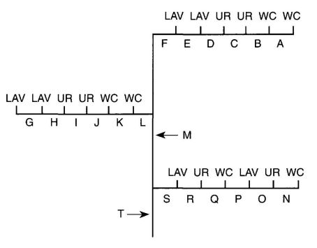
SIZING METHOD EXAMPLE USING TABLE 6-7 PUBLIC USE FIXTURES
In the example below, fixture units assigned to each section of pipe are computed as follows: Note: Each capital letter refers to the section of pipe above it, unless otherwise shown.
A: 1 WC = 40 F.U.
B: 2 WC = 70 F.U.
C: 2 WC (70) + 1 UR (20) = 90 F.U.
D: 2 WC (70) + 2 UR (35) = 105 F.U.
E: 2 WC (70) + 2 UR (35) + 1 LAV (1) = 106 F.U.
F: 2 WC (70) + 2 UR (35) + 2 LAV (2) = 107 F.U.
G: 1 LAV = 1 F.U.
H: 2 LAV = 2 F.U.
I: 2 LAV (2) + 1 UR (20) = 22 F.U.
J: 2 LAV (2) + 2 UR (35) = 37 F.U.
K: 2 LAV (2) + 2 UR (35) + 1 WC (40) = 77 F.U.
L: 2 LAV (2) + 2 UR (35) + 2 WC (70) = 107 F.U.
M: 4 WC (105) + 4 UR (53) + 4 LAV (4) = 162 F.U.
N: 1 WC = 40 F.U.
O: 1 WC (40) + 1 UR (20) = 60 F.U.
P: 1 WC (40) + 1 UR (20) + 1 LAV (1) = 61 F.U.
Q: 2 WC (70) + 1 UR (20) + 1 LAV (1) = 91 F.U.
R: 2 WC (70) + 2 UR (35) + 1 LAV (1) = 106 F.U.
S: 2 WC (70) + 2 UR (35) + 2 LAV (2) = 107 F.U.
T: 6 WC (125) + 6 UR (63) + 6 LAV (6) = 194 F.U.
610.11 Sizing Systems for Flushometer Tanks. The size of branches and mains serving flushometer tanks shall be consistent with the sizing procedures for flush tank water closets.
610.12 Sizing for Velocity. Water piping systems shall not exceed the maximum velocities listed in this section or Appendix A.
610.12.1 Copper Tube Systems. Maximum velocities in copper and copper alloy tube and fitting systems shall not exceed eight (8) feet per second (fps) (2.4 mps) in cold water and five (5) fps in hot water (1.5 mps).
610.12.2 Tubing Systems Using Copper Alloy Fittings. Maximum velocities through copper alloy fittings in tubing other than copper shall not exceed eight (8) feet per second (fps) (2.4 mps) in cold water and five (5) fps in hot water (1.5 mps).
610.13 Exceptions. The provisions of this section relative to size of water piping shall not apply to the following:
| Inch ½ ¾ 1 | mm 15 20 25 | ||||||
|---|---|---|---|---|---|---|---|
| APPLIANCES, APPURTENANCES OR FIXTURES2 | MINIMUM FIXTURE BRANCH PIPE SIZE1,4 | PRIVATE | PUBLIC | ASSEMBLY6 | |||
| Notes: | |||||||
| 1Size of the cold branch pipe, or both the hot and cold branch pipes. | |||||||
| 2Appliances, Appurtenances or Fixtures not included in this Table may be sized by reference to fixtures having a similar flow rate and frequency of use. | |||||||
| 3The listed fixture unit values represent their load on their cold water service. The separate cold water and hot water fixture unit value for fixtures having both hot and cold water connections may each be taken as three-quarter (¾) of the listed total value of the fixture. | |||||||
| 4The listed minimum supply branch pipe sizes for individual fixtures are the nominal (I.D.) pipe size. | |||||||
| 5For fixtures or supply connections likely to impose continuous flow demands, determine the required flow in gallons per minute (GPM), and add it separately to the demand (in GPM) for the distribution system or portions thereof. | |||||||
| 6Assembly [Public Use (See Table 4-1)]. | |||||||
| 7When sizing flushometer systems, see Section 610.10. | |||||||
| 8Reduced fixture unit loading for additional hose bibbs is to be used only when sizing total building demand and for pipe sizing when more than one (1) hose bibb is supplied by a segment of water-distributing pipe. The fixture branch to each hose bibb is supplied by a segment of water-distributing pipe. The fixture branch to each hose bibb shall be sized on the basis of two and one-half (2.5) fixture units. | |||||||
| 9[HCD 2] For water supply fixture unit values related to mobilehome parks in all parts of the State of California, see California Code of Regulations, Title 25, Division 1, Chapter 2, Article 5, Section 1278. For water supply fixture unit values related to special occupancy parks in all parts of the State of California, see California Code of Regulations, Title 25, Division 1, Chapter 2.2, Article 5, Section 2278. | |||||||
| Bathtub or Combination Bath/Shower (fill) | ½ | 4.0 | 4.0 | B | |||
| ¾" Bathtub Fill Valve | ¾ | 10.0 | 10.0 | ||||
| Bidet | ½ | 1.0 | |||||
| Clothes washer | ½ | 4.0 | 4.0 | ||||
| Dental Unit, cuspidor | ½ | 1.0 | |||||
| Dishwasher, domestic | ½ | 1.5 | 1.5 | ||||
| Drinking Fountain or Water Cooler | ½ | 0.5 | 0.5 | 0.75 | |||
| Hose Bibb | ½ | 2.5 | 2.5 | ||||
| Hose Bibb, each additional8 | ½ | 1.0 | 1.0 | ||||
| Lavatory | ½ | 1.0 | 1.0 | 1.0 | |||
| Lawn Sprinkler, each head5 | 1.0 | 1.0 | |||||
| Mobile Home, each (minimum)9 | 12.0 | ||||||
| Sinks | |||||||
| Bar | ½ | 1.0 | 2.0 | ||||
| Clinic Faucet | ½ | 3.0 | |||||
| Clinic Flushometer Valve with or without faucet | 1 | 8.0 | |||||
| Kitchen, domestic | ½ | 1.5 | 1.5 | ||||
| Laundry | ½ | 1.5 | 1.5 | ||||
| Service or Mop Basin | ½ | 1.5 | 3.0 | ||||
| Washup, each set of faucets | ½ | 2.0 | |||||
| Shower, per head | ½ | 2.0 | 2.0 | ||||
| Urinal, 1.0 GPF Flushometer Valve | ¾ | See Footnote7 | |||||
| Urinal, greater than 1.0 GPF Flushometer Valve | ¾ | See Footnote7 | |||||
| Urinal, flush tank | ½ | 2.0 | 2.0 | 3.0 | |||
| Wash Fountain, circular spray | ¾ | 4.0 | |||||
| Water Closet, 1.6 GPF Gravity Tank | ½ | 2.5 | 2.5 | 3.5 | |||
| Water Closet, 1.6 GPF Flushometer Tank | ½ | 2.5 | 2.5 | 3.5 | |||
| Water Closet, 1.6 GPF Flushometer Valve | 1 | See Footnote7 | |||||
| Water Closet, greater than 1.6 GPF Gravity Tank | ½ | 3.0 | 5.5 | 7.0 | |||
| Water Closet, greater than 1.6 GPF Flushometer Valve | 1 | See Footnote7 | |||||
| Inch ½ 3/4 1 1¼ 1½ 2 2½ | mm 15 20 25 32 40 50 65 | |||||||||||||||||
|---|---|---|---|---|---|---|---|---|---|---|---|---|---|---|---|---|---|---|
| METER AND STREET SERVICE, INCHES | BUILDING SUPPLY AND BRANCHES, INCHES | MAXIMUM ALLOWABLE LENGTH IN FEET (meters) | ||||||||||||||||
| 40 (12) | 60 (18) | 80 (24) | 100 (30) | 150 (46) | 200 (61) | 250 (76) | 300 (91) | 400 (122) | 500 (152) | 600 (183) | 700 (213) | 800 (244) | 900 (274) | 1000 (305) | ||||
| **Available static pressure after head loss. | ||||||||||||||||||
| ***Building supply, not less than three-quarter (¾) inch (20 mm) nominal size. | ||||||||||||||||||
| Pressure Range - 30 to 45 psi (207 to 310 kPa)** | ||||||||||||||||||
| ¾ | ½*** | 6 | 5 | 4 | 3 | 2 | 1 | 1 | 1 | 0 | 0 | 0 | 0 | 0 | 0 | 0 | ||
| ¾ | ¾ | 16 | 16 | 14 | 12 | 9 | 6 | 5 | 5 | 4 | 4 | 3 | 2 | 2 | 2 | 1 | ||
| ¾ | 1 | 29 | 25 | 23 | 21 | 17 | 15 | 13 | 12 | 10 | 8 | 6 | 6 | 6 | 6 | 6 | ||
| 1 | 1 | 36 | 31 | 27 | 25 | 20 | 17 | 15 | 13 | 12 | 10 | 8 | 6 | 6 | 6 | 6 | ||
| ¾ | 1¼ | 36 | 33 | 31 | 28 | 24 | 23 | 21 | 19 | 17 | 16 | 13 | 12 | 12 | 11 | 11 | ||
| 1 | 1¼ | 54 | 47 | 42 | 38 | 32 | 28 | 25 | 23 | 19 | 17 | 14 | 12 | 12 | 11 | 11 | ||
| 1½ | 1¼ | 78 | 68 | 57 | 48 | 38 | 32 | 28 | 25 | 21 | 18 | 15 | 12 | 12 | 11 | 11 | ||
| 1 | 1½ | 85 | 84 | 79 | 65 | 56 | 48 | 43 | 38 | 32 | 28 | 26 | 22 | 21 | 20 | 20 | ||
| 1½ | 1½ | 150 | 124 | 105 | 91 | 70 | 57 | 49 | 45 | 36 | 31 | 26 | 23 | 21 | 20 | 20 | ||
| 2 | 1½ | 151 | 129 | 129 | 110 | 80 | 64 | 53 | 46 | 38 | 32 | 27 | 23 | 21 | 20 | 20 | ||
| 1 | 2 | 85 | 85 | 85 | 85 | 85 | 85 | 82 | 80 | 66 | 61 | 57 | 52 | 49 | 46 | 43 | ||
| 1½ | 2 | 220 | 205 | 190 | 176 | 155 | 138 | 127 | 120 | 104 | 85 | 70 | 61 | 57 | 54 | 51 | ||
| 2 | 2 | 370 | 327 | 292 | 265 | 217 | 185 | 164 | 147 | 124 | 96 | 70 | 61 | 57 | 54 | 51 | ||
| 2 | 2½ | 445 | 418 | 390 | 370 | 330 | 300 | 280 | 265 | 240 | 220 | 198 | 175 | 158 | 143 | 133 | ||
| Pressure Range - 46 to 60 psi (317 to 414 kPa)** | ||||||||||||||||||
| ¾ | ½*** | 7 | 7 | 6 | 5 | 4 | 3 | 2 | 2 | 1 | 1 | 1 | 0 | 0 | 0 | 0 | ||
| ¾ | ¾ | 20 | 20 | 19 | 17 | 14 | 11 | 9 | 8 | 6 | 5 | 4 | 4 | 3 | 3 | 3 | ||
| ¾ | 1 | 39 | 39 | 36 | 33 | 28 | 23 | 21 | 19 | 17 | 14 | 12 | 10 | 9 | 8 | 8 | ||
| 1 | 1 | 39 | 39 | 39 | 36 | 30 | 25 | 23 | 20 | 18 | 15 | 12 | 10 | 9 | 8 | 8 | ||
| ¾ | 1¼ | 39 | 39 | 39 | 39 | 39 | 39 | 34 | 32 | 27 | 25 | 22 | 19 | 19 | 17 | 16 | ||
| 1 | 1¼ | 78 | 78 | 76 | 67 | 52 | 44 | 39 | 36 | 30 | 27 | 24 | 20 | 19 | 17 | 16 | ||
| 1½ | 1¼ | 78 | 78 | 78 | 78 | 66 | 52 | 44 | 39 | 33 | 29 | 24 | 20 | 19 | 17 | 16 | ||
| 1 | 1½ | 85 | 85 | 85 | 85 | 85 | 85 | 80 | 67 | 55 | 49 | 41 | 37 | 34 | 32 | 30 | ||
| 1½ | 1½ | 151 | 151 | 151 | 151 | 128 | 105 | 90 | 78 | 62 | 52 | 42 | 38 | 35 | 32 | 30 | ||
| 2 | 1½ | 151 | 151 | 151 | 151 | 150 | 117 | 98 | 84 | 67 | 55 | 42 | 38 | 35 | 32 | 30 | ||
| 1 | 2 | 85 | 85 | 85 | 85 | 85 | 85 | 85 | 85 | 85 | 85 | 85 | 85 | 85 | 83 | 80 | ||
| 1½ | 2 | 370 | 370 | 340 | 318 | 272 | 240 | 220 | 198 | 170 | 150 | 135 | 123 | 110 | 102 | 94 | ||
| 2 | 2 | 370 | 370 | 370 | 370 | 368 | 318 | 280 | 250 | 205 | 165 | 142 | 123 | 110 | 102 | 94 | ||
| 2 | 2½ | 654 | 640 | 610 | 580 | 535 | 500 | 470 | 440 | 400 | 365 | 335 | 315 | 285 | 267 | 250 | ||
| Pressure Range - Over 60 psi (414 kPa)** | ||||||||||||||||||
| ¾ | ½*** | 7 | 7 | 7 | 6 | 5 | 4 | 3 | 3 | 2 | 1 | 1 | 1 | 1 | 1 | 0 | ||
| ¾ | ¾ | 20 | 20 | 20 | 20 | 17 | 13 | 11 | 10 | 8 | 7 | 6 | 6 | 5 | 4 | 4 | ||
| ¾ | 1 | 39 | 39 | 39 | 39 | 35 | 30 | 27 | 24 | 21 | 17 | 14 | 13 | 12 | 12 | 11 | ||
| 1 | 1 | 39 | 39 | 39 | 39 | 38 | 32 | 29 | 26 | 22 | 18 | 14 | 13 | 12 | 12 | 11 | ||
| ¾ | 1¼ | 39 | 39 | 39 | 39 | 39 | 39 | 39 | 39 | 34 | 28 | 26 | 25 | 23 | 22 | 21 | ||
| 1 | 1¼ | 78 | 78 | 78 | 78 | 74 | 62 | 53 | 47 | 39 | 31 | 26 | 25 | 23 | 22 | 21 | ||
| 1½ | 1¼ | 78 | 78 | 78 | 78 | 78 | 74 | 65 | 54 | 43 | 34 | 26 | 25 | 23 | 22 | 21 | ||
| 1 | 1½ | 85 | 85 | 85 | 85 | 85 | 85 | 85 | 85 | 81 | 64 | 51 | 48 | 46 | 43 | 40 | ||
| 1½ | 1½ | 151 | 151 | 151 | 151 | 151 | 151 | 130 | 113 | 88 | 73 | 51 | 51 | 46 | 43 | 40 | ||
| 2 | 1½ | 151 | 151 | 151 | 151 | 151 | 151 | 142 | 122 | 98 | 82 | 64 | 51 | 46 | 43 | 40 | ||
| 1 | 2 | 85 | 85 | 85 | 85 | 85 | 85 | 85 | 85 | 85 | 85 | 85 | 85 | 85 | 85 | 85 | ||
| 1½ | 2 | 370 | 370 | 370 | 370 | 360 | 335 | 305 | 282 | 244 | 212 | 187 | 172 | 153 | 141 | 129 | ||
| 2 | 2 | 370 | 370 | 370 | 370 | 370 | 370 | 370 | 340 | 288 | 245 | 204 | 172 | 153 | 141 | 129 | ||
| 2 | 2½ | 654 | 654 | 654 | 654 | 654 | 650 | 610 | 570 | 510 | 460 | 430 | 404 | 380 | 356 | 329 | ||
| FIXTURE CATEGORY: WATER CLOSET W/ FLUSHOMETER VALVES | ||
| NUMBER OF FLUSHOMETER VALVES | INDIVIDUAL FIXTURE UNITS ASSIGNED IN DECREASING VALUE | FIXTURE UNITS ASSIGNED FOR WATER CLOSETS AND SIMILAR 10-UNIT FIXTURES IN ACCUMULATIVE VALUES |
| 1 | 40 | 40 |
| 2 | 30 | 70 |
| 3 | 20 | 90 |
| 4 | 15 | 105 |
| 5 or more | 10 each | 115 plus 10 for each additional fixture in excess of 5 |
| FIXTURE CATEGORY: URINALS W/ FLUSHOMETER VALVES | ||
| NUMBER OF FLUSHOMETER VALVES | INDIVIDUAL FIXTURE UNITS ASSIGNED IN DECREASING VALUE | FIXTURE UNITS ASSIGNED FOR WATER CLOSETS AND SIMILAR 5-UNIT FIXTURES IN ACCUMULATIVE VALUES |
| 1 | 20 | 20 |
| 2 | 15 | 35 |
| 3 | 10 | 45 |
| 4 | 8 | 53 |
| 5 or more | 5 each | 58 plus 5 for each additional fixture in excess of 5 |
| REQUIRED SIZE OF SOFTENER CONNECTION | NUMBER OF BATHROOM GROUPS SERVED1 |
|---|---|
| 1Installation of a kitchen sink and dishwasher, laundry tray, and automatic clothes washer permitted without additional size increase. | |
| 2An additional water closet and lavatory permitted. | |
| 3Over four (4) bathroom groups, the softener size shall be engineered for the specific installation. | |
| See also Appendix A, Recommended Rules for Sizing the Water Supply System, and Appendix L, Alternate Plumbing Systems, for alternate methods of sizing water supply systems. | |
| ¾ in. | up to 22 |
| 1 in. | up to 43 |
611.0 Drinking Water Treatment Units.
611.1 Compliance with Standard. Drinking water treatment units shall meet the requirements of the appropriate standard referenced in Table 14-1.
611.2 Airgap Discharge. Discharge from drinking water treatment units shall enter the drainage system through an airgap or an airgap device that meets the requirements of the appropriate standards referenced in Table 14-1.
611.3 Connection Tubing. The tubing to and from drinking water treatment units shall be of a size and material as recommended by the manufacturer. The tubing shall comply with the requirements of the appropriate standards referenced in Table 14-1.
611.4 Sizing of Residential Softeners. Residential-use water softeners shall be sized per Table 6-8.
612.0 [OSHPD 1, 2, 3 & 4] Domestic Hot-Water Distribution Systems for Health Facilities and Clinics.
612.1 The domestic water-heating equipment and distribution systems shall supply water at the temperature and amounts shown in Table 6-9. Where the system is designed by a mechanical engineer, appropriate diversity factors may be utilized.
| CLINICAL | DIETARY1 | LAUNDRY2 | |
|---|---|---|---|
| 1 Rinse water temperature at automatic dishwashing equipment and pot sinks shall be 180°F(82°C). Exception: The rinse water supply to pot rinse sinks may be deleted if a method of chemical disinfection using a three-compartment sink is proposed. | |||
| 2 The required temperature of 160°F (71°C) in the laundry is that measure in the washing machine and shall be supplied so that the temperature may be maintained over the entire wash and rinse period. Exception: A lower water temperature of 140°F (60°C) may be utilized, provided linens are subsequently passed through a tumbler dryer at 180°F (82°C) or a flatwork ironer at 300°F (149°C). | |||
| Liter/Hour/Bed | 11.9 | 7.2 | 7.6 |
| Gallons/Hour/Bed | 3 | 2 | 2 |
| Temperature °C | 41-49.0 | 49.0 | 71.0 |
| Temperature °F | 105-120.0 | 120.0 | 160.0 |
612.2 At least two pieces of hot-water-heating equipment shall be provided to supply hot water for dishwashing and minimum patient services such as handwashing and bathing. Booster heaters for 125°F to 180°F (52°C to 82°C) water are acceptable as a second piece of equipment for dishwashing. Where storage tanks are separate from the water heater, at least two independent storage tanks shall be provided.
612.3 Instantaneous heaters are permitted for supplying hot water to handwashing and bathing fixtures if a continuous mechanical recirculation system is also provided.
612.4 Water storage tanks shall be fabricated of corrosion-resistant materials or lined with corrosion-resistant materials.
612.5 Temperature control valves shall be provided to automatically regulate the temperature of hot water delivered to plumbing fixtures used by patients to a range of 105°F (41°C) minimum to 120°F (49°C) maximum. High temperature alarm set at 125°F (52°C) shall be provided. The audible/visual device for the high temperature alarm shall annunciate at a continuously occupied location.
612.6 Hot-water distribution system serving patient care areas shall be under constant mechanical recirculation to provide
continuous hot water at each hot water outlet. Non-recirculated fixture branch piping shall not exceed 25 feet (7.62 meters) in length. Dead-end piping (risers with no flow, branches with no fixture) shall not be installed. In renovation projects, dead-end piping shall be removed in the area of renovation. Empty risers, mains, and branches installed for future use shall be permitted.
612.7 At fixtures where water exceeding 125°F (52°C) is accessible to patients or personnel, warning signs in letters at least 2 inches (51 mm) high shall be posted above the fixtures.
612.8 Sectionalizing valves shall be provided as required by Section 605.8.
613.0 Dialysis Water-Distribution Systems.
613.1 [OSHPD 1, 2, 3 & 4] Dialysis water feedlines shall be PVC (polyvinyl chloride), glass, stainless steel, or PVDF (polyvinylidene fluoride) and sized to provide a minimum velocity of 1.5 feet per second (0.46 m/s). The piping shall be a singleloop system with or without recirculation. Branches to dialysis machines shall be ¼ inch (6.4 mm) inside dimension and take off from the bottom of the main feedline.
613.2 All piping for multistation or central dialysis units shall be rigid where possible. All piping and tubing shall be in a neat arrangement. The placement of piping or tubing on the floor is not permitted.
613.3 All valves shall be located in accessible locations.
613.4 Piping and valves shall be identified according to their function.
613.5 A means of preventing backwashing or flushing of the system when one or more stations are in operation shall be provided.
613.6 A continuous audible alarm shall sound at the nurses' station and remote equipment rooms when the minimum velocity is not maintained, or if backwashing or flushing is attempted while one or more stations are in operation.
613.7 Water used for dialysis treatment shall meet the latest edition of ANSI/American Association of Medical Instrumentations (AAMI) RD62, Water treatment equipment for hemodialysis applications.
613.8 A diagram of all piping as installed shall be posted at the nurses' station and equipment room of all multistation or central dialysis units.
614.0 Identification of Potable and Non-Potable Water Lines.
614.1 Uses Not Permitted.
614.1.1 [OSHPD 1, 2, 3 & 4] Non-potable water shall not be piped for drinking, washing or bathing, washing of clothing, cooking, washing of food, washing of cooking or eating utensils, washing of food preparation or processing premises, or other personal service rooms.
614.2 [OSHPD 1, 2, 3 & 4] Non-potable water systems or systems carrying any other non-potable substance shall be installed so as to prevent backflow or back-siphonage into a potable water system.
614.3 [OSHPD 1, 2, 3 & 4] Outlets for non-potable water, such as water for industrial or fire-fighting purposes, shall be posted in a manner understandable to all employees to indicate that the water is unsafe and shall not be used for drinking, washing, cooking, or other personal service purposes.
614.4 [OSHPD 1] Emergency Water Supply.
614.4.1 For acute care hospital facilities required to meet NPC-5, an on site water supply of 150 gallons (567.9 L) (based on 50 gallons/day/bed for 72 hours) of potable water per licensed bed shall be provided.
The emergency supply shall have fittings to allow for replenishment of the water supply from transportable water sources and a means to collect water in portable containers in the event that normal water supply becomes unavailable.
Exceptions:
- With the licensing agency approval of a water rationing plan, the emergency water storage capacity may be computed based on the approved water rationing plan to provide for 72 hours of operation.
- With the approval of the Office and the licensing agency, hook-ups that allow for the use of transportable sources of potable water may be provided in lieu of on-side storage.
614.4.2 The emergency supply of water shall be provided at adequate pressure using gravity, pressure tanks or booster pumps. Pumps used for this purpose shall be provided with electrical power from the on site emergency system.
| Adopting Agency | BSC | SFM | HCD | DSA | OSHPD | CSA | DPH | AGR | DWR | CA | |||||||
|---|---|---|---|---|---|---|---|---|---|---|---|---|---|---|---|---|---|
| 1 | 2 | 1/AC | AC | SS | SS/CC | 1 | 2 | 3 | 4 | ||||||||
| Adopt Entire Chapter | X | X | |||||||||||||||
| Adopt Entire Chapter as amended (amended sections listed below) | X | X | X | X | X | X | X | X | |||||||||
| Adopt only those sections that are listed below | |||||||||||||||||
| Chapter/Section | |||||||||||||||||
| 701.1.2.1 | X | X | X | X | |||||||||||||
| 701.1.2.2 | X | X | |||||||||||||||
| Table 7-3 | X | ||||||||||||||||
| 705.1.7 Exception | X | X | |||||||||||||||
| 705.1.9 Exception | X | X | |||||||||||||||
| 705.2.5 | X | X | |||||||||||||||
| 710.3.3.1 | X | X | |||||||||||||||
| 713.4 | X | X | |||||||||||||||
| 717.1 | X | ||||||||||||||||
| 724.0 | X | ||||||||||||||||
| 725.0 | X | ||||||||||||||||
| 726.0 | X | ||||||||||||||||
| 727.0 | X | ||||||||||||||||
701.0 Materials.
701.1 Materials for drainage piping shall be in accordance with one of the referenced standards in Table 7–1 except that:
701.1.1 No galvanized wrought-iron or galvanized steel pipe shall be used underground and shall be kept not less than six (6) inches (152 mm) above ground.
701.1.2 ABS and PVC DWV piping installations shall be installed in accordance with applicable standards referenced in Table 14-1. Except for individual single-family dwelling units, materials exposed within ducts or plenums shall have a flame-spread index of a maximum of twenty-five (25) and a smoke-developed index of a maximum fifty (50), when tested in accordance with the Test for Surface-Burning Characteristics of the Building Materials (See the Building Code standards based on ASTM E 84 and UL 723).
701.1.2.1 [OSHPD 1, 2, 3 & 4] ABS and PVC installations are not allowed.
701.1.2.2 [HCD 1 & HCD 2] ABS and PVC installations are limited to not more than two stories of areas of residential accommodation.
701.1.3 No vitrified clay pipe or fittings shall be used above ground or where pressurized by a pump or ejector. They shall be kept not less than twelve (12) inches (305 mm) belowground.
701.1.4 Copper tube for drainage and vent piping shall have a weight of not less than that of copper drainage tube type DWV.
701.1.5 Stainless steel 304 pipe and fittings shall not be installed underground and shall be kept not less than six (6) inches (152 mm) above ground.
701.1.6 Cast-iron soil pipe and fittings shall be listed and tested to comply with standards referenced in Table 14-1. Such pipe and fittings shall be marked with country of origin and identification of the original manufacturer in addition to any markings required by referenced standards.
701.2 Materials for drainage fittings shall be in accordance with the applicable standards referenced in Table 7-1 of the same diameter as the piping served, and such fittings shall be compatible with the type of pipe used.
701.2.1 Fittings on screwed pipe shall be of the recessed drainage type. Burred ends shall be reamed to the full bore of the pipe.
701.2.2 The threads of drainage fittings shall be tapped so as to allow one-fourth (¼) inch per foot (20.8 mm/m) grade.
701.2.3 Fittings used for drainage shall be of the drainage type, have a smooth interior water-way, and be constructed so as to allow one-fourth (¼) inch per foot (20.8 mm/m) grade.
701.3 Lead. See Table 14-1. Sheet lead shall be not less than the following:
For safe pans – not less than four (4) pounds per square foot (19.5 kg/m2) or one-sixteenth (1/16)inch (1.6 mm) thick.
For flashings or vent terminals – not less than three (3) pounds per square foot (14.6 kg/m2) or 0.0472 inches (1.2 mm) thick.
Lead bends and lead traps shall be not less than one-eighth (1/18) inch (3.2 mm) wall thickness.
701.4 Ferrules and Bushings.
701.4.1 Caulking ferrules shall be manufactured from bronze or copper and shall be in accordance with Table 7-2(a).
701.4.2 Soldering bushings shall be of bronze or copper in accordance with Table 7-2(b).
| PIPE SIZE (inches) | INSIDE DIAMETER (inches) | LENGTH (inches) | MINIMUM WEIGHT EACH | |
|---|---|---|---|---|
| lb. | oz. | |||
| 2 | 2¼ | 4½ | 1 | 0 |
| 3 | 3¼ | 4½ | 1 | 12 |
| 4 | 4¼ | 4½ | 2 | 8 |
| PIPE SIZE (mm) | INSIDE DIAMETER (mm) | LENGTH(mm) | MINIMUM WEIGHT EACH (kg) |
|---|---|---|---|
| 50 | 57 | 114 | 0.454 |
| 80 | 83 | 114 | 0.790 |
| 100 | 108 | 114 | 1.132 |
| PIPE SIZE (inches) | MINIMUM WEIGHT EACH | PIPE SIZE (inches) | MINIMUM WEIGHT EACH | ||
|---|---|---|---|---|---|
| lb. | oz. | lb. | oz. | ||
| 1¼ | 0 | 6 | 2½ | 1 | 6 |
| 1½ | 0 | 8 | 3 | 2 | 0 |
| 2 | 0 | 14 | 4 | 3 | 8 |
| PIPE SIZE (mm) | MINIMUM WEIGHT EACH (kg) | PIPE SIZE (mm) | MINIMUM WEIGHT EACH (kg) |
|---|---|---|---|
| 32 | 0.168 | 65 | 0.622 |
| 40 | 0.224 | 80 | 0.908 |
| 50 | 0.392 | 100 | 1.586 |
702.0 Fixture Unit Equivalents.
702.1 The unit equivalent of plumbing fixtures shown in Table 7-3 shall be based on the size of the trap required, and the unit equivalent of fixtures and devices not shown in Table 7-3 shall be based on the size of trap or trap arm.
Maximum drainage fixture units for a fixture trap and trap arm loadings for sizes up to four (4) inches (100 mm) are as follows:
| SIZE OF TRAP AND TRAP ARM | DRAINAGE FIXTURE UNIT VALUES (DFU) | |
|---|---|---|
| 1¼in. | (32 mm) | 1 unit |
| 1½in. | (40 mm) | 3 units |
| 2 in. | (50 mm) | 4 units |
| 3 in. | (80 mm) | 6 units |
| 4 in. | (100 mm) | 8 units |
| Exception: On self-service laundries. | ||
702.2 Drainage fixture units for intermittent flow into the drainage system shall be computed on the rated discharge capacity in gpm (gallons per minute) (liters per second) in accordance with Table 7–4.
702.3 For a continuous flow into a drainage system, such as from a pump, sump ejector, air conditioning equipment, or similar device, two (2) fixture units shall be allowed for each gallon per minute (3.78 L/m) of flow.
| GPM | (L/sec) | |
|---|---|---|
| Note: Discharge capacity exceeding 50 gallons per minute (3.15 L/sec.) shall be determined by the Authority Having Jurisdiction. | ||
| Up to 7½ | Up to 0.47 | Equals 1 Fixture Units |
| Greater than 7½ to 15 | (0.47 to 0.95) | Equals 2 Fixture Units |
| Greater than 15 to 30 | (0.95 to 1.89) | Equals 4 Fixture Units |
| Greater than 30 to 50 | (1.89 to 3.15) | Equals 6 Fixture Units |
703.0 Size of Drainage Piping.
703.1 The minimum sizes of vertical and/or horizontal drainage piping shall be determined from the total of fixture units connected thereto, and additionally, in the case of vertical drainage pipes, in accordance with their length.
| MATERIAL | UNDERGROUND DRAIN, WASTE, VENT PIPE AND FITTINGS | ABOVE GROUND DRAIN, WASTE VENT PIPE AND FITTINGS | BUILDING SEWER PIPE AND FITTINGS | REFERENCED STANDARD(S) PIPE | REFERENCED STANDARD(S) FITTINGS |
|---|---|---|---|---|---|
| 1For Building Sewer applications. | |||||
| ABS (Schedule 40) | X | X | X | ASTM D 1527, ASTM D 2661, ASTM D 26801, ASTM F 628 | ASTM D 2661, ASTM D 26801 |
| Asbestos-Cement | X | ASTM C 4281, ASTM C 141 | |||
| Brass | X | ASTM B 43 | |||
| Cast-Iron | X | X | X | ASTM A 74, ASTM A 888, CISPI 301 | ASME B 16.12, ASTM A 74, ASTM A 888, CISPI 301 |
| Co-Extruded ABS (Schedule 40) | X | X | X | ASTM F 1488 | ASTM D 2661 ASTM D 26801 |
| Co-Extruded PVC (Schedule 40) | X | X | X | ASTM F 1488, ASTM F 891 | ASTM D 2665, ASTM F 7941, ASTM F 1866 |
| Copper (Type DWV) | X | X | X | ASTM B 75 ASTM B 251, ASTM B 302, ASTM B 306 | ASME B 16.23, ASME B 16.29 |
| Galvanized Malleable Iron | X | ASME B 16.3 | |||
| Galvanized Steel | X | ASTM A 53 | |||
| PVC (Schedule 40) | X | X | X | ASTM D 1785, ASTM D 2665, ASTM F 7941 | ASTM D 2665, ASTM F 7941, ASTM F 1866 |
| Stainless Steel 304 | X | ASME A 112.3.1 | ASME A 112.3.1 | ||
| Stainless Steel 316L | X | X | X | ASME A 112.3.1 | ASME A 112.3.1 |
| Vitrified Clay (Extra strength) | X | ASTM C 700 | ASTM C 700 | ||
| APPLIANCES, APPURTENANCES OR FIXTURES2 | MINIMUM FIXTURE BRANCH PIPE SIZE1,4 | PRIVATE | PUBLIC | ASSEMBLY6 |
|---|---|---|---|---|
| 1 Indirect waste receptors shall be sized based on the total drainage capacity of the fixtures that drain therein to, in accordance with Table 7-4. | ||||
| 2 Provide a two (2) inch (51 mm) minimum drain. | ||||
| 3 For refrigerators, coffee urns, water stations, and similar low demands. | ||||
| 4 For commercial sinks, dishwashers, and similar moderate of heavy demands. | ||||
| 5 Buildings having a clothes-washing area with clothes washers in a battery of three (3) or more clothes washers shall be rated at six (6) fixture units each for purposes of sizing common horizontal and vertical drainage piping. | ||||
| 6 Water closets shall be computed as six (6) fixture units when determining septic tank sizes based on Appendix K of this code. | ||||
| 7 Trap sizes shall not be increased to the point where the fixture discharge may be inadequate to maintain their self-scouring properties. | ||||
| 8 Assembly [Public Use (See Table 4-1)]. | ||||
| 9 [HCD 2] For drainage fixture unit values related to mobilehome parks in all parts of the State of California, see California Code of Regulations, Title 25, Division 1, Chapter 2, Article 5, Section 1268. For drainage fixture unit values related to special occupancy parks in all parts of the State of California, see California Code of Regulations, Title 25, Division 1, Chapter 2.2, Article 5, Section 2268. | ||||
| Bathtub or Combination Bath/Shower | 1½ | 2.0 | 2.0 | |
| Bidet | 1¼ | 1.0 | ||
| Bidet | 1½ | 2.0 | ||
| Clothes Washer, domestic, standpipe5 | 3.0 | 3.0 | 3.0 | |
| Dental Unit, cuspidor | 1¼ | 1.0 | 1.0 | |
| Dishwasher, domestic, with independent drain2 | 1½ | 2.0 | 2.0 | 2.0 |
| Drinking Fountain or Water Cooler | 1¼ | 0.5 | 0.5 | 1.0 |
| Food-Waste-Grinder, commercial | 2 | 3.0 | 3.0 | |
| Floor Drain, emergency | 2 | 0.0 | 0.0 | |
| Floor Drain (for additional sizes see Section 702) | 2 | 2.0 | 2.0 | 2.0 |
| Shower, single-head trap | 2 | 2.0 | 2.0 | 2.0 |
| Multi-head, each additional | 2 | 1.0 | 1.0 | 1.0 |
| Lavatory, single | 1¼ | 1.0 | 1.0 | 1.0 |
| Lavatory, in sets of two or three | 1½ | 2.0 | 2.0 | 2.0 |
| Washfountain | 1½ | 2.0 | 2.0 | |
| Washfountain | 2 | 3.0 | 3.0 | |
| Mobile Home, trap9 | 3 | 12.0 | ||
| Receptor, indirect waste1,3 | 1½ | See footnote1,3 | ||
| Receptor, indirect waste1,4 | 2 | See footnote1,4 | ||
| Receptor, indirect waste1 | 3 | See footnote1 | ||
| Sinks | ||||
| Bar | 1½ | 1.0 | ||
| Bar2 | 1½ | 2.0 | 2.0 | |
| Clinical | 3 | 6.0 | 6.0 | |
| Commercial with food waste2 | 1½ | 3.0 | 3.0 | |
| Special Purpose2 | 1½ | 2.0 | 3.0 | 3.0 |
| Special Purpose | 2 | 3.0 | 4.0 | 4.0 |
| Special Purpose | 3 | 6.0 | 6.0 | |
| Kitchen, domestic2 | 1½ | 2.0 | 2.0 | |
| (With or without food-waste grinder and/or dishwasher) | ||||
| Laundry2 | 1½ | 2.0 | 2.0 | 2.0 |
| (With or without discharge from a clothes washer) | ||||
| Service or Mop Basin | 2 | 3.0 | 3.0 | |
| Service or Mop Basin | 3 | 3.0 | 3.0 | |
| Service, flushing rim | 3 | 6.0 | 6.0 | |
| Wash, each set of faucets | 2.0 | 2.0 | ||
| Urinal, integral trap 1.0 GPF2 | 2 | 2.0 | 2.0 | 5.0 |
| Urinal, integral trap greater than 1.0 GPF2 | 2 | 2.0 | 2.0 | 6.0 |
| Urinal, exposed trap2 | 1½ | 2.0 | 2.0 | 5.0 |
| Water Closet, 1.6 GPF Gravity Tank6 | 3 | 3.0 | 4.0 | 6.0 |
| Water Closet, 1.6 GPF Flushometer Tank6 | 3 | 3.0 | 4.0 | 6.0 |
| Water Closet, 1.6 GPF Flushometer Valve6 | 3 | 3.0 | 4.0 | 6.0 |
| Water Closet, greater than 1.6 GPF Gravity Tank6 | 3 | 4.0 | 6.0 | 8.0 |
| Water Closet, greater than 1.6 GPF Flushometer Valve6 | 3 | 4.0 | 6.0 | 8.0 |
703.2 Table 7-5 shows the maximum number of fixture units allowed on any vertical or horizontal drainage pipe, building drain, or building sewer of a given size; the maximum number of fixture units allowed on any branch interval of a given size; and the maximum length (in feet and meters) of any vertical drainage pipe of a given size.
703.3 For alternate method of sizing drainage piping, see Appendix L.
704.0 Fixture Connections (Drainage).
704.1 Drainage piping shall be provided with approved inlet fittings for fixture connections, correctly located according to the size and type of fixture proposed to be connected.
704.2 Two (2) fixtures set back-to-back, or side-by-side, within the distance allowed between a trap and its vent shall be permitted to be served by a single vertical drainage pipe provided that each fixture wastes separately into an approved double-fixture fitting having inlet openings at the same level.
704.3 Pot sinks, scullery sinks, dishwashing sinks, silverware sinks, commercial dishwashing machines, silverware-washing machines, and other similar fixtures shall be connected directly to the drainage system. A floor drain shall be provided adjacent to the fixture, and the fixture shall be connected on the sewer side of the floor drain trap, provided that no other drainage line is connected between the floor drain waste connection and the fixture drain. The fixture and floor drain shall be trapped and vented as required by this code.
705.0 Joints and Connections.
705.1 Types of Joints.
705.1.1 Caulked Joints. Caulked joints for cast-iron bell-and-spigot soil pipe and other similar joints shall be firmly packed with oakum or hemp and filled with molten lead to a depth of not less than one (1) inch (25.4 mm). The lead shall be caulked thoroughly at the inside and outside edges of the joint. After caulking, the finished joint shall not exceed one-eighth (1/8) inch (3.2 mm) below the rim of the hub. No paint, varnish, or other coatings shall be permitted on the joining material until after the joint has been tested and approved. Caulked joints in cast-iron bell-and-spigot water piping shall be made with nontoxic materials.
705.1.2 Cement Mortar Joints. Except for repairs and connections to existing lines constructed with such joints, cement mortar joints shall be prohibited on building sewers.
705.1.3 Burned Lead Joints. Burned (welded) lead joints shall be lapped, and the lead shall be fused together to form a uniform weld not less than as thick as the lead being joined.
705.1.4 Asbestos Cement Sewer Pipe Joints. Joints in asbestos cement pipe shall be a sleeve coupling of the same composition as the pipe or of other approved materials, and sealed with rubber rings or joined by an approved-type compression coupling. Joints between asbestos cement pipe and other approved pipe shall be made by means of an approved adapter coupling.
| SIZE OF PIPE, inches (mm) | 1¼ (32) | 1½ (40) | 2 50 | 2½ (65) | 3 (80) | 4 (100) | 5 (125) | 6 (150) | 8 (200) | 10 (250) | 12 (300) |
|---|---|---|---|---|---|---|---|---|---|---|---|
| 1 Excluding trap arm. | |||||||||||
| 2 Except sinks, urinals, and dishwashers-exceeding one(1) fixture unit. | |||||||||||
| 3 Except six-unit traps or water closets. | |||||||||||
| 4 Only four(4) water closets or six-unit traps allowed on any vertical pipe or stack and not to exceed three (3) water closets or six-unit traps on any horizontal branch or drain. | |||||||||||
| 5 Based on one-fourth(¼) inch per foot (20.8 mm/m) slope. For one-eighth (1/8) inch per foot (10.4 mm/m) slope, multiply horizontal fixture units by a factor of eight-tenths(0.8). | |||||||||||
|
Note: The diameter of an individual vent shall be not less than one and one-fourth(1¼)inches (32 mm) not less than one-half (½) the diameter of the drain to which it is connected. Fixture unit load values for drainage and vent piping shall be computed from Table 7-3 and 7-4. Not to exceed one-third (1/3) of the total permitted length of any vent may be installed in a horizontal position. When vents are increased one (1) pipe size for their entire length, the maximum length limitations specified in this table do not apply. This table complies with the requirements of Section 901.2. | |||||||||||
| Maximum Units | |||||||||||
| Drainage Piping | |||||||||||
| Vertical | 1 | 22 | 163 | 323 | 484 | 256 | 600 | 1380 | 3600 | 5600 | 8400 |
| Horizontal | 1 | 1 | 83 | 143 | 354 | 2165 | 4285 | 7205 | 26405 | 46805 | 82005 |
| Maximum Length | |||||||||||
| Drainage Piping | |||||||||||
| Vertical, feet (m) | 45 | 65 | 85 | 148 | 212 | 300 | 390 | 510 | 750 | ||
| Horizontal (unlimited) | (14) | (20) | (26) | (45) | (65) | (91) | (119) | (155) | (228) | ||
| Vent Piping | |||||||||||
| Horizontal and Vertical | 1 | 83 | 24 | 48 | 84 | 256 | 600 | 1380 | 3600 | ||
| Maximum Units | 45 | 60 | 120 | 180 | 212 | 300 | 390 | 510 | 750 | ||
| Maximum Lengths, feet (m) | (14) | (14) | (14) | (14) | (14) | (14) | (14) | (14) | (14) | ||
705.1.5 Packing Additives Prohibited. The addition of leak-sealing additives to joint packing shall be prohibited.
705.1.6 Molded Rubber Coupling Joints. When pipe is joined by means of molded rubber coupling joints, such joints shall conform to approved standards and shall not be considered as slip joints. When required, appropriate rubber bushings shall be used to allow for any difference in piping material diameters.
705.1.7 Elastomeric Gasketed and Rubber-Ring Joints. Elastomeric gasketed and rubber-ring joints shall comply with the applicable standards referenced in Table 14-1.
Exception: [HCD 1 & HCD 2] Compliance with an approved nationally recognized installation standard complying with Section 310.4 of this code and approved by the Enforcing Agency is acceptable.
705.1.8 Shielded Coupling Joints. When piping systems are joined by means of shielded couplings, such couplings shall conform to approved standards and shall not be considered as slip joints.
705.1.9 Hubless Cast-Iron Pipe Joints. Joints for hubless cast-iron soil pipe and fittings shall conform to applicable standards referenced in Table 14-1 and shall not be considered as slip joints.
Exception: [HCD 1 & HCD 2] Compliance with an approved nationally recognized installation standard complying with Section 310.4 of this code and approved by the Enforcing Agency is acceptable.
705.2 Use of Joints.
705.2.1 Clay and Sewer Pipe. Joints in vitrified clay pipe or between such pipe and metal pipe shall be made as provided in Sections 316.1.5, 705.1.6, 705.1.7, or 705.1.8.
705.2.2 Cast-Iron Pipe. Joints in cast-iron pipe shall be made as provided in Sections 316.1.2, 316.1.5, 705.1.1, 705.1.8, or 705.1.9.
705.2.3 Screw Pipe to Cast-Iron. Joints between wrought iron, steel, brass, or copper pipe and cast-iron pipe shall be either caulked or threaded joints made as provided in Section 316.1.1 or 705.1.1, or shall be made with approved adapter fittings.
705.2.4 Lead to Cast-Iron, Wrought-Iron, or Steel. Joints between lead and cast-iron, wrought-iron, or steel pipe shall be made by means of wiped joints to a caulking ferrule, soldering nipple, or bushing as provided in Section 316.1.2.
705.2.5 ABS and PVC Pipe [HCD 1 & HCD 2] Joints in ABS and PVC pipe shall be made as provided in Section 316.1.6 of this code.
705.3 Special Joints.
705.3.1 Slip Joints. In fixture drains and traps, slip joints of approved materials shall be permitted to be used in accordance with their approvals.
705.3.2 Expansion Joints. Expansion joints shall be accessible, except when in vent piping or drainage stacks, and shall be permitted to be used where necessary to provide for expansion and contraction of the pipes.
705.3.3 Ground Joint, Flared, or Ferrule Connections. Brass or copper ground joint, flared, or ferrule type connections that allow adjustment of tubing, but provide a rigid joint when made up, shall not be considered as slip joints.
706.0 Changes in Direction of Drainage Flow.
706.1 Changes in direction of drainage piping shall be made by the appropriate use of approved fittings and shall be of the angles presented by a one-sixteenth (1/16) bend, one-eighth (1/8) bend, or one-sixth (1/6) bend, or other approved fittings of equivalent sweep.
706.2 Horizontal drainage lines, connecting with a vertical stack, shall enter through 45 degree (0.79 rad) wye branches, 60 degree (1.05 rad) wye branches, combination wye and one-eighth (1/8) bend branches, sanitary tee or sanitary tapped tee branches, or other approved fittings of equivalent sweep. No fitting having more than one (1) inlet at the same level shall be used unless such fitting is constructed so that the discharge from one (1) inlet cannot readily enter any other inlet. Double Sanitary tees shall be permitted to be used when the barrel of the fitting is not less than two (2) pipe sizes larger than the largest inlet, (pipe sizes recognized for this purpose are 2 in., 2½in., 3 in., 3½in, 4 in.,4½ 5 in., 6 in., etc.) (50, 65, 80, 90, 100, 115, 125, 150 mm, etc.).
706.3 Horizontal drainage lines connecting with other horizontal drainage lines shall enter through 45 degree (0.79 rad) wye branches, combination wye and one-eighth (1/8) bend branches, or other approved fittings of equivalent sweep.
706.4 Vertical drainage lines connecting with horizontal drainage lines shall enter through 45 degree (0.79 rad) wye branches, combination wye and one-eighth (1/8) bend branches, or other approved fittings of equivalent sweep. Branches of off-sets of 60 degrees (1.05 rad) shall be permitted to be used only when installed in a true vertical position.
707.0 Cleanouts.
707.1 Each cleanout fitting for cast-iron pipe shall consist of a cast-iron or brass body and an approved plug. Each cleanout for galvanized wrought-iron, of a galvanized steel, copper, or brass pipe shall consist of a brass plug as specified in Table 7-6, or a standard weight brass cap, or an approved ABS or PVC plastic plug, or an approved stainless steel cleanout or plug. Plugs shall have raised square heads or approved counter sunk rectangular slots.
707.2 Each cleanout fitting and each cleanout plug or cap shall be of an approved type.
707.3 Cleanouts shall be designed to be gas and water-right.
707.4 Each horizontal drainage pipe shall be provided with a cleanout at its upper terminal, and each run of piping that is more than one-hundred (100) feet (30,480 mm) in total developed length, shall be provided with a cleanout for each one-hundred (100) feet (30,480 mm), or fraction thereof, in length of such piping. An additional cleanout shall be provided in a drainage line for each aggregate horizontal change of direction exceeding 135 degrees (2.36 rad).
Exceptions:
- Cleanouts shall be permitted to be omitted on a horizontal drain line less than five (5) feet (1.524 mm) in length unless such line is serving sinks or urinals.
- Cleanouts shall be permitted to be omitted on any horizontal drainage pipe installed on a slope of 72 degrees (1.26 rad) or less from the vertical angle (one-fifth (1/5) bend.)
- Excepting the building drain and its horizontal branches, a cleanout shall not be required on any pipe or piping that is above the floor level of the lowest floor of the building.
- An approved type of two-way cleanout fitting, installed inside the building wall near the connection between the building drain and the building sewer or installed outside of a building at the lower end of a shall be permitted to be substituted for an upper terminal cleanout.
707.5 Each cleanout shall be installed so that it opens to allow cleaning in the direction of flow of the soil or waste or at right angles thereto and, except in the case of wye branch and end-of-line cleanouts, shall be installed vertically above the flow line of the pipe.
707.6 Each cleanout extension shall be considered as drainage piping and each 90 degree (1.6 rad) cleanout extension shall be extended from a wye-type fitting or other approved fitting of equivalent sweep.
707.7 Each cleanout for an interceptor shall be outside of such interceptor.
707.8 Each cleanout, unless installed under an approved cover plate, shall be above grade, readily accessible, and so located as to serve the purpose for which it is intended. Cleanouts located under cover plates shall be so installed as to provide the clearances and accessibility required by this section.
707.9 Each cleanout in piping two (2) inches (50 mm) or less in size shall be so installed that there is a clearance of not less than twelve (12) inches (305 mm) in front of the cleanout. Cleanouts in piping exceeding two (2) inches (50 mm) shall have a clearance of not less than eighteen (18) inches (457 mm) in front of the cleanout. Clean outs in under-floor piping shall be extended to or above the finished floor or shall be extended outside the building when there is less than eighteen (18) inches (457 mm) vertical overall, allowing for obstructions such as ducts, beams, and piping, and thirty (30) inches (762 mm) horizontal clearance from the means of access to such cleanout. No under-floor cleanout shall be located exceeding twenty (20) feet (6.096 mm) from an access door, trap door, or crawl hole.
707.10 Cleanout fittings shall be not less in size than those given in Table 7-6.
707.11 Cleanouts shall be provided for pressure drainage systems as classified under Section 710.7.
707.12 Countersunk cleanout plugs shall be installed where raised heads cause a hazard.
707.13 When a hubless blind plug is used for a required cleanout, the complete coupling and plug shall be accessible for removal or replacement.
| SIZE OF PIPE (inches) | SIZE OF CLEANOUT (inches) | THREADS (per inches) |
|---|---|---|
| 1½ | 1½ | 11½ |
| 2 | 1½ | 11½ |
| 2½ | 2½ | 8 |
| 3 | 1½ | 8 |
| 4 & larger | 3½ | 8 |
| SIZE OF PIPE (mm) | SIZE OF CLEANOUT (mm) | THREADS (per 25.4 mm) |
|---|---|---|
| 40 | 40 | 11½ |
| 50 | 40 | 11½ |
| 65 | 65 | 8 |
| 80 | 65 | 8 |
| 100 & larger | 90 | 8 |
707.14 Cleanouts for trap arms shall be installed in accordance with Section 1002.3.
708.0 Grade of Horizontal Drainage Piping.
Horizontal drainage piping shall be run in practical alignment and a uniform slope of not less than one-fourth (¼) inch per foot (20.8 mm/m) or 2 percent toward the point of disposal provided that, where it is impractical due to the depth of the street sewer, to the structural features, or to the arrangement of any building or structure to obtain a slope of one-fourth (¼) of an inch per foot (20.8 mm/m) or 2 percent, any such pipe or piping four (4) inches (100 mm) or larger in diameter may have a slope of not less than one-eighth (1/8) of an inch per foot (10.4 mm/m) or 1 percent, when first approved by the Authority Having Jurisdiction.
709.0 Gravity Drainage Required.
Wherever practicable, plumbing fixtures shall be drained to the public sewer or private sewage disposal system by gravity.
710.0 Drainage of Fixtures Located Below the Next Up-stream Manhole or Below the Main Sewer Level.
710.1 Where a fixture is installed on a floor level that is lower than the next upstream manhole cover of the public or private sewer, serving such drainage piping, shall be protected from backflow of sewage by installing an approved type of backwater valve. Fixtures on floor levels above such elevation shall not discharge through the backwater valve. Cleanouts for drains that pass through a backwater valve shall be clearly identified with a permanent label stating “backwater valve downstream”.
710.2 Drainage piping serving fixtures that are located below the crown level of the main sewer shall discharge into an approved water-tight sump or receiving tank, so located as to receives the sewage or wastes by gravity. From such sump or
receiving tank, the sewage or other liquid wastes shall be lifted and discharged into the building drain or building sewer by approved ejectors, pumps, or other equally efficient approved mechanical devices.
710.3 A sewage ejector or sewage pump receiving the discharge of water closets or urinals:
710.3.1 Shall have a discharge capacity of not less than 20 gallons per minute (75.7 L/m).
710.3.2 In single dwelling units, the ejector or pump shall be capable of passing a one and one-half (1½) inch (38 mm) diameter solid ball, and the discharge piping of each ejector or pump shall have a backwater valve and gate valve, and be not less than of two (2) inches (50 mm) in diameter.
710.3.3 In other than single-dwelling, units, the ejector or pump shall be capable of passing a two (2) inch (51 mm) diameter solid ball, and the discharge piping of each ejector or pump shall have a backwater valve and gate valve, and be not less than three (3) inches (80 mm) in diameter.
710.3.3.1 [HCD 1 & HCD 2] The minimum size of any pump or any discharge pipe from a sump having a water closed connected thereto shall be not less than (2) inches (51 mm).
710.4 The discharge line from such ejector, pump, or other mechanical device shall be provided with an accessible backwater or swing check valve and gate or ball valve. If the gravity drainage line to which such discharge line connects is horizontal, the method of connection shall be from the top through a wye branch fitting. The gate or ball valve shall be located on the discharge side of the back water or check valve.
Gate or ball valves, when installed in drainage piping, shall be fullway type with working parts of corrosion-resistant metal. Sizes four (4) inches (100 mm) or more in diameter shall have cast-iron bodies, and sizes less than four (4) inches. (100 mm). cast-iron or brass bodies.
710.5 Building drains or building sewers receiving discharge from any pump or ejector shall be adequately sized to prevent overloading. Two (2) fixture units shall be allowed for each gallon per minute (3.78 L/m) of flow.
710.6 Backwater valves, gate valves, fullway ball valves, unions, motors, compressors, air tanks, and other mechanical devices required by this section shall be located where they will be accessible for inspection and repair at all times and, unless continuously exposed, shall be enclosed in a masonry pit fitted with an adequately sized removable cover.
Backwater vales shall have bodies of cast-iron, plastic, brass, or other approved materials; shall have noncorrosive bearings, seats, and self-aligning doses; and shall be constructed so as to ensure a positive mechanical seal. Such backwater valves shall remain sufficiently open during periods of low flows to avoid screening of solids and shall not restrict capacities or cause excessive turbulence during peak loads. Unless otherwise listed, valve access covers shall be bolted type with gasket, and each valve shall bear the manufacturer's name cast into the body and the cover.
710.7 The drainage and venting systems, in connection with fixtures, sumps, receiving tanks, and mechanical waste-lifting devices, shall be installed under the same requirements as provided for in this code for gravity systems.
710.8 Sumps and receiving tanks shall be water-tight and shall be constructed of concrete, metal, or other approved materials. If constructed of poured concrete, the walls and bottom shall be adequately reinforced and designed to recognized acceptable standards. Metal sumps or tanks shall be of such thickness as to serve their intended purpose and shall be treated internally and externally to resist corrosion.
710.9 Such sumps and receiving tanks shall be automatically discharged and, when in any “public use” occupancy, shall be provided with dual pumps or ejectors arranged to function alternately in normal use and independently in case of overload or mechanical failure. The pumps shall have an audio and visual alarm, readily accessible, that signals pump failure or an overload condition. The lowest inlet shall have a clearance of not less than two (2) inches (51 mm) from the high-water or “starting” level of the sump.
710.10 Sumps and receiving tanks shall be provided with substantial covers having a bolt-and-gasket- type manhole or equivalent opening to permit access for inspection, repairs, and cleaning. The top shall be provided with a vent pipe that shall extend separately through the roof or, where permitted, be combined with other vent pipes. Such vent shall be large enough to maintain atmospheric pressure within the sump under normal operating conditions and, in no case, shall be less in size than that required by Table 7-5 for the number and type of fixtures discharging into the sump, nor less than one and one-half (1½) inches (40 mm) in diameter. When the foregoing requirements are met and the vent, after leaving the sump, is combined with vents from fixtures discharging into the sump, the size of the combined vent need not exceed that required for the total number of fixtures discharging into the sump. No vent from an air operating sewage ejector shall combine with other vents.
710.11 Air tanks shall be so proportioned as to be of equal cubical capacity to the ejectors connected therewith in which there shall be maintained an air pressure of not less than two (2) pounds for each foot (3 kg for each m) of height the sewage is to be raised. No water-operated ejectors shall be permitted.
710.12 Grinder Pump Ejector. Grinder pumps shall be permitted to be used.
710.12.1 Discharge Piping. The discharge piping shall be sized per the manufacturer's instructions and shall be not less than one and one-fourth (1¼) inches (32 mm) in diameter. A check valve and fullways-type shutoff valve shall be located within the discharge line.
710.13 Macerating Toilet Systems. Listed macerating toilet systems shall be permitted as an alternate to a sewage pump system when approved by the Authority Having Jurisdiction.
710.13.1 Sumps. The sump shall be water-and gas-tight.
710.13.2 Discharge Piping. The discharge piping shall be sized per manufacturer's instructions and shall be not less than three-quarter (¾) inches (20 mm) in diameter. The developed length of the discharge piping shall not exceed
the manufacturer's recommendations. A check valve and fullway-type shutoff valve shall be located within the discharge line or internally within the device.
710.13.3 Venting. The plumbing fixtures that discharge into the macerating device shall be vented per this code. The sump shall be vented per manufacturer's instructions and such vent shall be permitted to connect to the fixture venting.
711.0 Suds Relief.
Drainage connections shall not be made into a drainage piping systems within eight (8) feet (2,438 mm) of any vertical to horizontal change of direction of a stack containing suds-producing fixtures. Bathtubs, laundries, washing machine standpipes, kitchen sinks, and dishwashers shall be considered suds-producing fixtures. Where parallel vent stacks are required, they shall connect to the drainage stack at a point eight (8) feet (2,438 mm) above the lowest point of the drainage stack.
Exceptions:
- Single-family residences.
- Stacks receiving the discharge from less than three (3) stories of plumbing fixtures.
712.0 Testing.
712.1 Media. The piping of the plumbing, drainage, and venting systems shall be tested with water or air except that plastic pipe shall not be tested with air. The Authority Having Jurisdiction shall be permitted to require the removal of any cleanouts. etc., to ascertain whether the pressure has reached all parts of the system. After the plumbing fixtures have been set and their traps filled with water, they shall be submitted to a final test.
712.2 Water Test. The water test shall be applied to the drainage and vent systems either in its entirety or in sections. If the test is applied to the entire system, openings in the piping shall be tightly closed, except the highest opening, and the system filled with water to point of overflow. If the system is tested in sections, each opening shall be tightly plugged, except the highest opening of the section under test, and each section shall be filled with water, but no section shall be tested with less than a ten (10) foot (3,048 mm) head of water. In testing successive sections, not less than the upper ten (10) feet (3,048 mm) of the next preceding section shall be tested, so that no joint or pipe in the building (except the uppermost ten (10) feet (3,048 mm) of the system) shall have been submitted to a test of less than a ten (10) foot (3,048 mm) head of water. The water shall be kept in the system, or in the portion under test, for not less than fifteen (15) minutes before inspection starts. The systems shall then be tight at points.
712.3 Air Test. The air test shall be made by attaching an air compressor testing apparatus to any suitable opening and, after closing all other inlets and outlets to the system, forcing air into the system until there is a uniform gauge pressure of five (5) pounds per square inch (34.5 kpa) or sufficient to balance a column of mercury ten (10) inches (254 mm) in height. The pressure shall be held without introduction of additional air for a period of not less than fifteen (15) minutes.
713.0 Sewer Required.
713.1 Every building in which plumbing fixtures are installed and every premises having drainage piping thereon shall have a connection to a public or private sewer, except as provided in Sections 101.4.1.3, 713.2, and 713.4.
713.2 When no public sewer intended to serve any lot or premises is available in any thoroughfare or right of way abutting such lot or premises, drainage piping from any building or works shall be connected to an approved private sewage disposal system.
713.3 Within the limits prescribed by Section 713.4 hereof, the rearrangement or subdivision into smaller parcels of a lot that abuts and is served by a public sewer shall not be deemed cause to permit the construction of a private sewage disposal system, and plumbing or drainage systems on any such smaller parcel or parcels shall connect to the public sewer.
713.4 The public sewer shall be permitted to be considered as not being available when such public sewer or any building or any exterior drainage facility connected thereto is located more than two-hundred (200) feet (61 m) from any proposed building or exterior drainage facility on any lot or premises that abuts and is served by such public sewer.
[HCD 1 & HCD 2] For residential occupancies, the public sewer may be considered as not being available by the Authority Having Jurisdiction.
713.5 No permit shall be issued for the installation, alteration, or repair of any private sewage disposal system, or part thereof, on any lot for which a connection with a public sewer is available.
713.6 On every lot or premises hereafter connected to a public sewer, all plumbing and drainage systems or parts thereof on such lot or premises shall be connected with such public sewer.
Exception: Single-family dwellings and buildings or structures accessory thereto, existing and connected to an approved private sewage disposal system prior to the time of connecting the premises to the public sewer shall be permitted, when no hazard, nuisance, or insanitary condition is evidenced and written permission has been obtained from the Authority Having Jurisdiction, remain connected to such properly maintained private sewage disposal system when there is insufficient grade or fall to permit drainage to the sewer by gravity.
714.0 Damage to Public Sewer or Private Sewage Disposal System.
714.1 It Shall be unlawful for any person to deposit, by any means whatsoever, into any plumbing fixture, floor drain, interceptor, sump, receptor, or device which is connected to any
drainage system, public sewer, private sewer, septic tank, or cesspool, any ashes; cinders; solids; rags; flammable, poisonous, or explosive liquids or gases; oils; grease; and any other thing whatsoever that would or could cause damage to the public sewer, private sewer, or private sewage disposal system.
714.2 No rain, surface, or subsurface water shall be connected to or discharged into any drainage system, unless first approved by the Authority Having Jurisdiction.
714.3 No cesspool, septic tank, seepage pit, or drain field shall be connected to any public sewer or to any building sewer leading to such public sewer.
714.4 The Authority Having Jurisdiction shall review before approval, the installation of a commercial food waste grinder connecting to a private sewage disposal system.
714.5 An approved-type water-light sewage or wastewater holding tank, the contents of which, due to their character, must be periodically removed and disposed of at some approved off-site location, shall be installed only when required by the Authority Having Jurisdiction or the Health Officer to prevent anticipated surface or subsurface contamination or pollution, damage to the public sewer, or other hazardous or nuisance conditions.
715.0 Building Sewer Materials.
715.1 The building sewer, beginning two (2) feet (610 mm) from any building or structure, shall be of such materials as prescribed in this code.
715.2 Joining methods and materials shall be as prescribed in this code.
715.3 Replacement of existing building sewer and building storm sewers using trenchless methodology and materials shall be installed in accordance with IAPMO IS-26.
716.0 Markings.
Pipe, brick, block, prefabricated septic tanks, prefabricated septic tank or seepage pit covers, or other parts or appurtenances incidental to the installation of building sewers or private sewage disposal systems shall conform to the approval requirements of Chapter 3 of this code.
717.0 Size of Building Sewers.
The minimum size of any building sewer shall be determined on the basis of the total number of fixture units drained by such sewer, in accordance with Table 7-8. No building sewer shall be smaller than the building drain.
For alternate methods of sizing building sewers, see Appendix L.
717.1 [AGR] Meat and Poultry Processing Plants. The sewer system shall have the capacity to remove all waste from the various processing and cleaning operations and to minimize or prevent stoppage and surcharging at the system.
718.0 Grade, Support, and Protection of Building Sewers.
718.1 Building sewers shall be run in practical alignment and at a uniform slope of not less than one-fourth (¼) of an inch per foot (20.8 mm/m) toward the point of disposal.
Exception: When approved by the Authority Having Jurisdiction and where it is impractical, due to the depth of the street sewer or to the structural features or to the arrangement of any building or structure, to obtain a slope of one-fourth (¼) of an inches per foot (20.8 mm/m), any such pipe or piping four (4) inches (100 mm) through six (6) inches (150 mm) shall be permitted to have a slope of not less than one-eighth (1/8) inch per foot (10.4 mm m) and any such piping eight (8) inches (200 mm) and larger shall be permitted to have a slope of not less than one-sixteenth (1/16) of an inch per foot (5.2 mm/m).
718.2 Building sewer piping shall be laid on a firm bed throughout its entire length, and any such piping laid in a made of filled-in ground shall be laid on a bed of approved materials and shall be properly supported as required by the Authority Having Jurisdiction.
718.3 No building sewer or other drainage piping or part thereof, which is constructed of materials other than those approved for use under or within a building, shall be installed under or within two (2) feet (610 mm) of any building or structure, or part thereof, nor less than one (1) foot (305 mm) below the surface of the ground. The provisions of this subsection include structures such as porches and steps, whether covered or uncovered; breezeways; roofed porte cocheres; roofed patios; carports; covered walks; covered driveways; and similar structures or appurtenances.
719.0 Cleanouts.
719.1 Cleanouts shall be placed inside the building near the connection between the building drain and the building sewer or installed outside the building at the lower end of the building drain and extended to grade.
Additional building sewer cleanouts shall be installed at intervals not to exceed one-hundred (100) feet (30.480 mm) in straight runs and for each aggregate horizontal change in direction exceeding one-hundred and thirty-five (135) degrees (2.36 rad).
719.2 When a building sewer or a branch thereof does not exceed ten (10) feet (3,048 mm) in length and is a straight-line projection from a building drain that is provided with a cleanout, no cleanout will be required at its point of connection to the building drain.
719.3 Required building sewer cleanouts shall be extended to grade and shall comply with the appropriate sections of Cleanouts, Section 707.0, for sizing, construction, and materials. When building sewers are located under buildings, the cleanout requirements of Section 707.0 shall apply.
719.4 Each cleanout shall be installed so that it opens to allow cleaning in the direction of flow of the soil or waste or at right
angles thereto and, except in the case of wye branch and end-of-line cleanouts, shall be installed vertically above the flow line of the pipe.
719.5 Cleanouts installed under concrete or asphalt paving shall be made accessible by yard boxes or by extending flush with paving with approved materials and shall be adequately protected.
719.6 Approved manholes shall be permitted to be installed in lieu of cleanout, when first approved by the Authority Having Jurisdiction. The maximum distance between manholes shall not exceed three-hundred (300) feet (91.4 m).
The inlet and outlet connections shall be made by the use of a flexible compression joint not less than twelve (12) inches (305 mm) and not exceeding three (3) feet (914 mm) from the manhole. No flexible compression joints shall be embedded in the manhole base.
720.0 Sewer and Water Pipes.
Building sewers or drainage piping of clay or materials that are not approved for use within a building shall not be run or laid in the same trench as the water pipes unless both of the following requirements are met:
Water pipes crossing sewer or drainage piping constructed of clay or materials that are not approved for use within a building shall be laid not less than twelve (12) inches (305 mm) above the sewer or drain pipe.
Note: For the purpose of this section, “within the building” shall mean within the fixed limits of the building foundation.
721.0 Location.
721.1 Except as provided in Section 721.2, no building sewer shall be located in any lot other than the lot that is the site of the building or structure served by such sewer not shall any building sewer be located at any point having less than the minimum distances indicated in Table 7-7.
721.2 Nothing contained in this code shall be construed to prohibit the use of all or part of an abutting lot to:
|
Note: | ||
| 1 Including porches and steps, whether covered or uncovered; breeze-ways; roofed portecocheres; roofed patios; carports; covered walks; covered driveways; and similar structures or appurtenances. | ||
| 2 See also Section 313.3 | ||
| 3 Drainage piping shall clear domestic water supply wells by not less than fifty (50) feet (15,240 mm). This distance shall be permitted to be reduced to not less than twenty-five (25) feet (7,620 mm) when the drainage piping is constructed of materials approved for use within a building. | ||
| 4 See Section 720.0. | ||
| 5 For parallel construction. | ||
| 6 For crossings, approval by the Health Department or Authority Having Jurisdiction shall be required. | ||
| Buildings or structures1 | 2 feet | (610 mm) |
| Property line adjoining private property | Clear2 | |
| Water supply wells | 50 feet3 | (15,240 mm) |
| Streams | 50 feet | (15,240 mm) |
| On-site domestic water service line | 1 foot4 | (305 mm) |
| Public water main | 10 feet5.6 | (3,048 mm) |
| SIZE OF PIPE, | SLOPE, INCHES PER FOOT (mm/m) | |||
|---|---|---|---|---|
| Inches | (mm) | 1/16; (5.2) | 1/8; (10.4) | ¼ (20.8) |
| See also Appendix K, Private Sewage Disposal Systems. For alternate methods of sizing drainage piping. see Appendix L. | ||||
| 6 and smaller | (150) | (As specified in Table 7-5/ No minimum loading) | ||
| 8 | (200) | 1,950/1,500 | 2,800/625 | 3,900/275 |
| 10 | (250) | 3,400/1,600 | 4,900/675 | 6,800/300 |
| 12 | (300) | 5,600/1,700 | 8,000/725 | 11,200/325 |
722.0 Abandoned Sewers and Sewage Disposal Facilities.
722.1 Every abandoned building (house) sewer, or part thereof, shall be plugged or capped in an approved manner within five (5) feet (1,524 mm) of the property line.
722.2 Every cesspool, septic tank, and seepage pit that has been abandoned or has been discontinued otherwise from further use, or to which no waste or soil pipe from a plumbing fixture use, or to which no waste or soil pipe from a plumbing fixture is connected, shall have the sewage removed therefrom and be completely filled with earth, sand, gravel, concrete, or other approved material.
722.3 The top cover or arch over the cesspool, septic tank, or seepage pit shall be removed before filling, and the filling shall not extend above the top of the vertical portions of the sidewalls or above the level of any outlet pipe until inspection has been called and the cesspool, septic tank, or seepage pit has been inspected, After such inspection, the cesspool, septic tank, or seepage pit shall be filled to the level of the top of the ground.
722.4 No person owning or controlling any cesspool, septic tank, or seepage pit on the premises of such person or in that portion of any public street, alley, or other public property abutting such premises, shall fail, refuse, or neglect to comply with the provisions of this section or upon receipt of notice so to comply from the Authority Having Jurisdiction.
722.5 Where disposal facilities are abandoned consequent to connecting any premises with the public sewer, the permittee making the connection shall fill abandoned facilities as required by the Authority Having Jurisdiction within thirty (30) days from the time of connecting to the public sewer.
723.0 Building Sewer Test.
Building sewers shall be tested by plugging the end of the building sewer at its points of connection with the public sewer or private sewage disposal system and completely filling the building sewer with water from the lowest to the highest point thereof, or by approved equivalent low-pressure air test. Plastic DWV piping systems shall not be tested by the air test method. The building sewer shall be water-tight at all points.
724.1 The drainage and plumbing systems must permit the quick runoff of all water from plant buildings, and of surface water around the plant buildings, and of surface water around the plant and on the premises; and all such water shall be disposed of in such a manner as to prevent a nuisance or health hazard.
724.2 Toilet soil lines shall be separated from house drainage line to a point outside the building unless an automatic back-water check valve is installed to prevent backflow. Drainage from toilet bowls and urinals shall not be discharged into a grease catch basin, nor shall such drainage be permitted to enter the sewer lines at a point where there might be a possibility of such drainage backing up and flooding the floor of the building.
725.0 [AGR] Collection Center and Facilities Drainage.
Drainage and plumbing systems shall meet the requirements of Section 724.1.
726.0 [AGR] Drainage and Plumbing, General.
726.1 The outer premises of every official establishment, including docks, areas where cars and other vehicles are loaded, driveways, approaches, yards, pens, and alleys, shall be drained.
726.2 Toilet soil lines shall be separated from house drainage lines to a point outside the building, and drainage from toilet bowls and urinals shall not be discharged into a grease catch basin.
727.0 [OSHPD 1] Emergency Sanitary Drainage.
727.1 For acute care hospital facilities required to meet NPC-5, an on-site emergency holding tank(s) sufficient to store 150 gallons (567.9L) (based on 50 gallons/day/bed for 72 hours) of waste water per licensed bed shall be provided. The emergency holding tanks shall have fittings to allow for transfer of the waste to other disposable sources, such as tank trucks.
Exceptions:
| Adopting Agency | BSC | SFM | HCD | DSA | OSHPD | CSA | DPH | AGR | DWR | CA | |||||||
|---|---|---|---|---|---|---|---|---|---|---|---|---|---|---|---|---|---|
| 1 | 2 | 1/AC | AC | SS | SS/CC | 1 | 2 | 3 | 4 | ||||||||
| Adopt Entire Chapter | X | X | X | X | X | X | X | X | X | ||||||||
| Adopt Entire Chapter as amended (amended sections listed below) |
|||||||||||||||||
| Adopt only those sections that are listed below |
|||||||||||||||||
| Chapter/Section | |||||||||||||||||
801.0 Indirect Wastes.
801.1 Airgap or Airbreak Required. Indirect waste piping shall discharge into the building drainage system through an airgap or airbreak as set forth in this code. Where a drainage airgap is required by this code, the minimum vertical distance as measured from the lowest point of the indirect waste pipe or the fixture outlet to the flood-level rim of the receptor shall be not less than one (1) inch (25.4 mm).
801.2 Food and Beverage Handling Establishments. Establishments engaged in the storage, preparation, selling, serving, processing, or other handling of food and beverage involving the following equipment that requires drainage shall provide indirect waste piping for refrigerators, refrigeration coils, freezers, walk-in coolers, iceboxes, ice-making machines, steam tables, egg boilers, coffee urns and brewers, hot-and-cold drink dispensers, and similar equipment.
801.2.1 Except for refrigeration coils and ice-making machines, the size of the indirect waste pipe shall not be smaller than the drain on the unit, but shall not be smaller than one (1) inch (25 mm), and the maximum developed length shall not exceed fifteen (15) feet (4,572 mm). Indirect waste pipe for ice-making machines shall be not less than the drain on the unit, and in no case less than three-quarters (¾ of an inch (20 mm).
801.2.2 For walk-in coolers, floor drains shall be permitted to be connected to a separate drainage line discharging into an outside receptor. The flood-level rim of the receptor shall be not less than six (6) inches (152 mm) lower than the lowest floor drain. Such floor drains shall be trapped and individually vented. Cleanouts shall be provided at every 90 degree (1.6 rad) turn and shall be accessibly located. Such waste shall discharge through an airgap or airbreak into a trapped and vented receptor, except that a full-size airgap is required where the indirect waste pipe is under vacuum.
801.2.3 Food-preparation sinks, steam kettles, potato peelers, ice cream dipper wells, and similar equipment shall be indirectly connected to the drainage system by means of an airgap. Bins, sinks, and other equipment having drainage connections and used for the storage of unpackaged ice used for human ingestion, or used in direct contact with ready-to-eat food, shall be indirectly connected to the drainage system by means of an airgap. Each indirect waste pipe from food-handling fixtures or equipment shall be separately piped to the indirect waste receptor and shall not combine with other indirect waste pipes. The piping from the equipment to the receptor shall be not less than the drain on the unit, and in no case less than one-half (½) of an inch (15 mm).
801.3 Bar and Fountain Sink Traps. Where the sink in a bar, soda fountain, or counter is so located that the trap serving the sink cannot be vented, the sink drain shall discharge through an airgap or airbreak (See Section 801.2.3) into an approved receptor that is vented. The developed length from the fixture outlet to the receptor shall not exceed five (5) feet (1,524 mm).
801.4 Connections from Water Distribution System. Indirect waste connections shall be provided for drains, overflows, or relief pipes from potable water pressure tanks, water heaters, boilers, and similar equipment that is connected to the potable water distribution system. Such indirect waste connections shall be made by means of a water-distribution airgap constructed in accordance with Table 6-3.
801.5 Sterilizers. Lines, devices, or apparatus such as stills, sterilizers, and similar equipment requiring waste connections and used for sterile materials shall be indirectly connected by means of an airgap. Each such indirect waste pipe shall be separately piped to the receptor and shall not exceed fifteen (15) feet (4,572 mm). Such receptors shall be located in the same room.
801.6 Drip or Drainage Outlets. Appliances, devices, or apparatus not regularly classified as plumbing fixtures, but which have drip or drainage outlets, shall be permitted to be drained by indirect waste pipes discharging into an open receptor through either an airgap or airbreak (See Section 801.2.1).
802.0 Approvals.
No plumbing fixtures served by indirect waste pipes or receiving discharge therefrom shall be installed until first approved by the Authority Having Jurisdiction.
803.0 Indirect Waste Piping.
Except as hereinafter provided, the size and construction of indirect waste piping shall be in accordance with other sections of this code applicable to drainage and vent piping. No vent from indirect waste piping shall combine with any sewer-connected vent, but shall extend separately to the outside air. Indirect waste pipes exceeding five (5) feet (1,524 mm), but less than fifteen (15) feet (4,572 mm) in length shall be directly trapped, but such traps need not be vented.
Indirect waste pipes less than fifteen (15) feet (4,572 mm) in length shall be not less than the diameter of the drain outlet or tailpiece of the fixture, appliance, or equipment served, and in no case less than one-half (½) of an inch (15 mm). Angles and changes of direction in such indirect waste pipes shall be provided with cleanouts so as to permit flushing and cleaning.
804.0 Indirect Waste Receptors.
804.1 Plumbing fixtures or other receptors receiving the discharge of indirect waste pipes shall be approved for the used proposed and shall be approved for the use proposed and shall be of such shape and capacity as to prevent
splashing or flooding and shall be located where they are readily accessible for inspection and cleaning. No standpipe receptor for any clothes washer shall extend more than thirty (30) inches (762 mm), or not less than eighteen (18) inches (457 mm) above its trap. No trap for any clothes washer standpipe receptor shall be installed below the floor, but shall be roughed in not less than six (6) inches (152 mm) and not more than eighteen (18) inches (457 mm) above the floor. No indirect waste receptor shall be installed in any toilet room, closet, cupboard, or storeroom, nor in any other portion of a building not in general use by the occupants thereof; except standpipes for clothes washers shall be permitted to be installed in toilet and bathroom areas when the clothes washer is installed in the same room.
804.2 Where water service connections are installed for a clothes washer, an approved method of waste disposal shall be provided.
805.0 Pressure Drainage Connections.
Indirect waste connections shall be provided for drains, overflows, or relief vents from the water supply system, and no piping or equipment carrying wastes or producing wastes or other discharges under pressure shall be directly connected to any part of the drainage system.
The foregoing shall not apply to any approved sump pump or to any approved pressure-wasting plumbing fixture or device when the Authority Having Jurisdiction has been satisfied that the drainage system is adequately sized to accommodate the anticipated discharge thereof.
806.0 Sterile Equipment.
Appliances, devices, or apparatus such as stills, sterilizers, and similar equipment requiring water and waste and used for sterile materials shall be drained through an airgap.
807.0 Appliances.
807.1 Appliances, devices, equipment, or other apparatus not regularly classed as plumbing fixtures, which are equipped with pumps, drips, or drainage outlets, shall be permitted to be drained by indirect waste pipes discharging into an approved type of open receptor.
807.2 When the condensate waste from air-conditioning coils discharges by direct connection to a lavatory tailpiece or to an approved accessible inlet on a bathtub overflow, the connection shall be located in the area controlled by the same person controlling the air-conditioned space.
807.3 When undiluted condensate waste from a fuel-burning condensing appliance is discharged into the drainage system, the material in the drainage system shall be cast-iron, galvanized iron, plastic, or other materials approved for this use.
Exceptions:
- When the above condensate is discharged to an exposed fixture tailpiece and trap, such tail-piece and trap shall be permitted to be brass.
- Any materials approved in Section 701.0 shall be permitted to be used when data is provided that the condensate waste is adequately diluted.
807.4 No domestic dishwashing machine shall be directly connected to a drainage system or food waste disposer without the use of an approved dishwasher airgap fitting on the discharge side of the dishwashing machine. Listed airgaps shall be installed with the flood-level (FL) marking at or above the flood level of the sink or drainboard, whichever is higher.
808.0 Cooling Water.
When permitted by the Authority Having Jurisdiction, clean running water used exclusively as a cooling medium in an appliance, device, or apparatus shall be permitted to discharge into the drainage system through the inlet side of a fixture trap in the event that a suitable fixture is not available to receive such discharge. Such trap connection shall be by means of a pipe connected to the inlet side of an approved fixture trap, the upper end terminating in a funnel-shaped receptacle set adjacent, and not less than six (6) inches (152 mm) above the overflow rim of the fixture.
809.0 Drinking Fountains.
Drinking fountains shall be permitted to be installed with indirect wastes.
810.0 Steam and Hot Water Drainage Condensers and Sumps.
810.1 No steam pipe shall be directly connected to any part of a plumbing or drainage system, nor shall any water having a temperature above 140°F (60°C) be discharged under pressure directly into any part of a drainage system. Pipes from boilers shall discharge by means of indirect waste piping, as determined by the Authority Having Jurisdiction or the boiler manufacturer's recommendations. Such pipes shall be permitted to be indirectly connected by discharging into an open or closed condenser or an intercepting sump of approved type that will prevent the entrance of steam or such water under pressure into the drainage system. Closed condensers or sumps shall be provided with a vent that shall be taken off the top and extended separately, full size above the roof. Condensers and sumps shall be properly trapped at the outlet with a deep seal trap extending to within six (6) inches (152 mm) of the bottom of the tank. The top of the deep seal trap shall have a three-fourths (¾) inch (19.1 mm) opening located at the highest point of the trap to serve as a siphon breaker. Outlets shall be taken off from the side in such a manner as to allow a waterline to be maintained that will permanently occupy not less than one-half (½) the capacity of the condenser or sump. Inlets shall enter above the waterline. Wearing plates or baffles shall be installed in the tank to protect the shell. The sizes of the blowoff line inlet, the water outlets, and the vent shall be as shown in Table 8-1. The contents of condensers receiving steam or hot water under pressure must pass through an open sump before entering the drainage system.
| BOILER BLOWOFF | WATER OUTLET | VENT | |||
|---|---|---|---|---|---|
| *To be used only with boilers of one-hundred (100) square feet (9.29 m2) of heating surface or less. | |||||
| ¾in.* | (20 mm) | ¾in.* | (20 mm) | 2 in. | (50 mm) |
| 1 in. | (25 mm) | 1 in. | (25 mm) | 2½ in. | (65 mm) |
| 1¼ in. | (32 mm) | 1¼ in. | (32 mm) | 3 in. | (80 mm) |
| 1½ in. | (40 mm) | 1½ in. | (40 mm) | 4 in. | (100 mm) |
| 2 in. | (50 mm) | 2 in. | (50 mm) | 5 in. | (125 mm) |
| 2½ in. | (65 mm) | 2½ in. | (65 mm) | 6 in. | (150 mm) |
810.2 Sumps, condensers, or intercepting tanks that are constructed of concrete shall have walls and bottom not less than four (4) inches (102 mm) in thickness, and the inside shall be cement plastered not less than one-half (½)inch (12.7 mm) in thickness. Condensers constructed of metal shall be not less than No. 12 U.S. standard gauge (0.109 inch) (2.77 mm), and such metal condensers shall be protected from external corrosion by an approved bituminous coating.
810.3 Sumps and condensers shall be provided with suitable means of access for cleaning and shall contain a volume of not less than twice the volume of water removed from the boiler or boilers connected thereto when the normal water level of such boiler or boilers is reduced not less than four (4) inches (102 mm).
810.4 Strainers. Every indirect waste interceptor receiving discharge-containing particles that would clog the receptor drain shall have a readily removable beehive strainer.
811.0 Chemical Wastes.
811.1 Chemical or industrial liquid wastes that are likely to damage or increase maintenance costs on the sanitary sewer system, detrimentally affect sewage treatment, or contaminate surface or subsurface waters shall be pretreated to render them innocuous prior to discharge into a drainage system. Detailed plans and specifications of the pretreatment facilities shall be required by the Authority Having Jurisdiction.
Piping conveying industrial, chemical, or process wastes from their point of origin to sewer-connected pretreatment facilities shall be of such material and design as to adequately perform its intended function to the satisfaction of the Authority Having Jurisdiction. Drainage discharge piping from pretreatment facilities or interceptors shall conform to standard drainage installation procedures.
Copper tube shall not be used for chemical or industrial wastes as defined in this section.
811.2 Each waste pipe receiving or intended to receive the discharge of any fixture into which acid or corrosive chemical is placed, and each vent pipe connected thereto, shall be constructed of Chlorinated Poly (viny1-chloride) (CPVC), Polypropylene (PP), Polyvinylidene Fluoride (PVDF), chemical-resistant glass, high-silicon iron pipe, or lead pipe with a wall thickness of not less than one-eighth (1/8)inch (3.2 mm); an approved type of ceramic glazed or unglazed vitrified clay; or other approved corrosion-resistant materials.
811.3 Joining materials shall be of approved type and quality.
811.4 Wherever practicable, piping shall be readily accessible and installed with the maximum of clearance from other services.
811.5 The owner shall make and keep a permanent record of the location of piping and venting carrying chemical waste.
811.6 No chemical vent shall intersect vents for other services.
811.7 Chemical wastes shall be discharged in a manner approved by the Authority Having Jurisdiction.
811.8 The provisions in this section relative to materials and methods of construction shall not apply to installations such as photographic or X-ray dark rooms or research or control laboratories where minor amounts of adequately diluted chemicals are discharged.
812.0 Clear Water Wastes.
Water lifts, expansion tanks, cooling jackets, sprinkler systems, drip or overflow pans, or similar devices that discharge clear wastewater into the building drainage system shall discharge through an indirect waste.
813.0 Swimming Pools.
Pipes carrying wastewater from swimming or wading pools, including pool drainage and backwash from filters, shall be installed as an indirect waste. Where a pump is used to discharge waste pool water to the drainage system, the pump discharge shall be installed as and indirect waste.
814.0 Condensate Wastes and Control.
814.1 Condensate Disposal. Condensate from air washers, air-cooling coils, fuel-burning condensing appliances, the overflow from evaporative coolers, and similar water-supplied equipment or similar air-conditioning equipment shall be collected and discharged to an approved plumbing fixture or disposal area. If discharged into the drainage system, equipment shall drain by means of an indirect waste pipe. The waste pipe shall have a slope of not less than one-eighth (1/8) inch per foot (10.4 mm/m) or 1 percent slope and shall be of approved corrosion-resistant material not smaller than the outlet size as required in Table 8-2 for air-cooling coils or condensing fuel-burning appliances, respectively. Condensate or wastewater shall not drain over a public way.
| EQUIPMENT CAPACITY IN TONS OF REFRIGERATION (kw) | MINIMUM CONDENSATE PIPE DIAMETER IN INCHES (mm) | ||
|---|---|---|---|
| Up to 20 | (Up to 70.34) | ¾ | (20) |
| 21-40 | (73.85-140.67) | 1 | (25) |
| 41-90 | (144.19-316.5) | 1¼ | (32) |
| 91-125 | (320.03-439.6) | 1½ | (40) |
| 126-250 | (443.12-879.2) | 2 | (50) |
814.2. Size. Air-conditioning condensate waste pipes shall be independent of any drainage and waste system and shall be not less than the minimum size shown in Table 8-2.
The size of condensate waste pipes is for one (1) unit or a combination of units, or as recommended by the manufacturer. The capacity of waste pipes assumes a one-eighth (1/8) inch per foot (10.4 mm/m) or 1 percent slope, with the following pipe conditions:
| Outside Air— 20% | Room Air —80% | ||
| DB | WB | DB | WB |
| 90°F | 73°F | 75°F | 62.5°F |
| (32°C) | (23°C) | (24°C) | (17°) |
Condensate drain sizing for other slopes or other conditions shall be approved by the Authority Having Jurisdiction.
Air-conditioning waste pipes shall be constructed of materials specified in Chapter 7.
814.3 Point of Discharge. Air-conditioning condensate waste pipes shall connect indirectly to the drainage system through an airgap or airbreak to a properly trapped and vented receptors dry wells, leach pits, or the tailpiece of plumbing fixtures.
Condensate waste shall not drain over a public way.
| Adopting Agency | BSC | SFM | HCD | DSA | OSHPD | CSA | DPH | AGR | DWR | CA | |||||||
|---|---|---|---|---|---|---|---|---|---|---|---|---|---|---|---|---|---|
| 1 | 2 | 1/AC | AC | SS | SS/CC | 1 | 2 | 3 | 4 | ||||||||
| Adopt Entire Chapter | X | X | |||||||||||||||
| Adopt Entire Chapter as amended (amended sections listed below) | X | X | X | X | X | X | X | ||||||||||
| Adopt only those sections that are listed below | |||||||||||||||||
| Chapter/Section | |||||||||||||||||
| 903.1.2.1 | X | X | X | X | |||||||||||||
| 903.1.3 | X | X | |||||||||||||||
| 903.1.4 | X | X | |||||||||||||||
| 906.2.1 | X | X | X | X | |||||||||||||
901.0 General.
901.1 Vents Required.
Each plumbing fixture trap, except as otherwise provided in this code, shall be protected against siphonage and back-pressure, and air circulation shall be ensured throughout all parts of the drainage system by means of vent pipes installed in accordance with the requirements of this chapter and as otherwise required by this code.
901.2 Trap Seal Protection. The vent system shall be designed to prevent a trap seal from being exposed to a pressure differential that exceeds one (1) inch of a water column (249 Pa) on the outlet side of the trap.
902.0 Vents Not Required.
902.1 Vent piping shall be permitted to be omitted on an interceptor when such interceptor acts as a primary settling tank and discharges through a horizontal indirect waste pipe into a secondary interceptor. The second interceptor shall be properly trapped and vented.
902.2 Traps serving sinks that are part of the equipment of bars, soda fountains, and counters need not be vented when the location and construction of such bars, soda fountains, and counters is such as to make it impossible to do so. When such conditions exist, said sinks shall discharge by means of approved indirect waste pipes into a floor sink or other approved type of receptor.
903.0 Materials.
903.1 Vent pipe and fittings shall be in accordance with the applicable standards referenced in Table 7-1, except that:
903.1.1 No galvanized steel or 304 stainless steel pipe shall be installed underground and shall be not less than six (6) inches (152 mm) above ground.
903.1.2 ABS and PVC DWV piping installations shall be in accordance with the applicable standards referenced in Table 14-1. Except for individual single-family dwelling units, materials exposed within ducts of plenums shall have a flame-spread index of a maximum of twenty-five (25) and a smoke-developed index of not more than fifty (50) when tested in accordance with the Test for Surface Burning Characteristics of the Building Materials (see the Building Code standards based on ASTM E 84 and UL 723).
903.1.2.1 [OSHPD 1, 2, 3 ' 4] ABS and PVC installations are not allowed.
903.1.3 [HCD 1 ' HCD 2] ABS or PVC installations are limited to not more than two stories of areas of residential accommodation.
903.1.4 [HCD 1 ' HCD 2] All malleable iron vents shall be galvanized.
903.2 Use of Copper Tubing.
903.2.1 Copper tube for underground drainage and vent piping shall have a weight of not less than that of copper drainage tube type DWV.
903.2.2 Copper tube for above ground drainage and vent piping shall have a weight of not less than that of copper drainage tube type DWV.
903.2.3 Copper tube shall not be used for chemical or industrial wastes as defined in Section 811.0.
903.2.4 Hard-drawn copper tubing, in addition to the required incised marking, shall be marked in accordance with either ASTM B 306, Standard for Copper Drainage Tube (DWV), or ASTM B 88, Standard for Seamless Copper Water Tube as listed in Table 14-1. The colors shall be: Type K, green; Type L, blue; Type M, red; Type DWV, yellow.
903.3 Changes in direction of vent piping shall be made by the appropriate use of approved fittings, and no such pipe shall be strained or bent. Burred ends shall be reamed to the full bore of the pipe.
904.0 Size of Vents.
904.1 The size of vent piping shall be determined from its length and the total number of fixture units connected thereto, as set forth in Table 7-5. The diameter of an individual vent shall be not less than one and one-fourth (1¼) inches (32 mm) nor less than one-half (½) the diameter of the drain to which it is connected. In addition, the drainage piping of each building and each connection to a public sewer or a private sewage disposal system shall be vented by means of one (1) or more vent pipes, the aggregate cross-sectional area of which shall be not less than that of the largest required building sewer, as determined from Table 7-5. Vent pipes from fixtures located upstream from pumps, ejectors, backwater valves, or other devices that in any way obstruct the free flow of air and other gases between the building sewer and the outside atmosphere shall not be used for meeting the cross-sectional area venting requirements of this section.
Exception: When connected to a common building sewer, the drainage piping of two (2) or more buildings located on the same lot and under one (1) ownership shall be permitted to be vented by means of piping sized in accordance with Table 7-5, provided the aggregate cross-sectional area of vents is not less than that of the largest required common building sewer.
904.2 No more than one-third (1/3;) of the total permitted length, per Table 7-5, of any minimum-sized vent shall be installed in a horizontal position.
Exception: When a minimum-sized vent is increased one (1) pipe size for its entire length, the maximum length limitation does not apply.
905.0 Vent Pipe Grades and Connections.
905.1 Vent and branch vent pipes shall be free from drops or sags, and each such vent shall be level or shall be so graded and connected as to drip back by gravity to the drainage pipe it serves.
905.2 Where vents connect to a horizontal drainage pipe, each vent pipe shall have its invert taken off above the drainage centerline of such pipe downstream of the trap being served.
905.3 Unless prohibited by structural conditions, each vent shall rise vertically to a point not less than six (6) inches (152 mm) above the flood-level rim of the fixture served before off-setting horizontally, and whenever two (2) or more vent pipes converge, each such vent pipe shall rise to a point not less than six (6) inches (152 mm) in height above the flood-level rim of the plumbing fixture it serves before being connected to any other vent. Vents less than six (6) inches (152 mm) above the flood-level rim of the fixture shall be installed with approved drainage fittings, material, and grade to the drain.
905.4 Vent pipes shall extend undiminished in size above the roof, or shall be reconnected with a soil or waste vent of proper size.
905.5 The vent pipe opening from a soil or waste pipe, except for water closets and similar fixtures, shall not be below the weir of the trap.
905.6 Two (2) fixtures shall be permitted to be served by a common vertical pipe when each such fixture wastes separately into an approved double fitting having inlet openings at the same level.
906.0 Vent Termination.
906.1 Each vent pipe or stack shall extend through its flashing and shall terminate vertically not less than six (6) inches (152 mm) above the roof nor less than one (1) foot (305 mm) from any vertical surface.
906.2 Each vent shall terminate not less than ten (10) feet (3,048 mm) from, or not less than three (3) feet (914 mm) above, any openable window, door, opening, air intake, or vent shaft, or not less than three (3) feet (914 mm) in every direction from any lot line, alley and street excepted.
906.2.1 [OSHPD 1, 2, 3 & 4] Each vent pipe shall terminate not less than twenty-five (25) feet (7620 mm) from any air intake or vent shaft.
906.3 Vent pipes shall be extended separately or combined, of full required size, not less than six (6) inches (152 mm) above the roof or fire wall. Flagpoling of vents shall be prohibited except where the roof is used for purposes other than weather protection. Vents within ten (10) feet (3,048 mm) of any part of the roof that is used for such other purposes shall extend not less than seven (7) feet (2,134 mm) above such roof and shall be securely stayed.
906.4 Vent pipes for outdoor installations shall extend not less than ten (10) feet (3,048 mm) above the surrounding ground and shall be securely supported.
906.5 Joints at the roof around vent pipes shall be made watertight by the use of approved flashings or flashing material.
906.6 Lead. See Table 14-1. Sheet lead shall be not less than the following:
For safe pans — not less than four (4) pounds per square foot (19.5 kg/m2) or one-sixteenth (1/16;) inch (1.6 mm) thick.
For flashings or vent terminals — not less than three (30 pounds per square foot (14.6 kg/m2).
Lead bends and lead traps shall be not less than one-eighth (1/8) inch (3.2 mm) wall thickness.
906.7 Frost or Snow Closure. Where frost or snow closure is likely to occur in locations having minimum design temperature below 0°F (-17.8°C), vent terminals shall be not less than two (2) inches (50 mm) in diameter, but in no event smaller than the required vent pipe. The change in diameter shall be made inside the building not less than one (1) foot (305 mm) below the roof in an insulated space and terminate not less than ten (10) inches (254 mm) above the roof, or as required by the Authority Having Jurisdiction.
907.0 Vent Stacks and Relief Vents.
907.1 Each drainage stack that extends ten (10) or more stories above the building drain or other horizontal drain, shall be served by a parallel vent stack, which shall extend undiminished in size from its upper terminal and connect to the drainage stack at or immediately below the lowest fixture drain. Each such vent stack shall also be connected to the drainage stack at each fifth floor, counting down from the uppermost fixture drain, by means of a yoke vent, the size of which shall be not less in diameter than either the drainage or the vent stack, whichever is smaller.
907.2 The yoke vent connection to the vent stack shall be placed not less than forty-two (42) inches (1,067 mm) above the floor level, and the yoke vent connection to the drainage stack shall be by means of a wye-branch fitting placed below the lowest drainage branch connection serving that floor.
908.0 Wet Venting.
908.1 Vertical Wet Venting.
908.1.1 Where Permitted. Wet venting is limited to vertical drainage piping receiving the discharge from the trap arm of one (1) and two (2) fixture unit fixtures that also serves as a vent not exceeding four (4) fixtures. Wet-vented fixtures shall be within the same story; provided, further, that fixtures with a continuous vent discharging into a wet vent shall be within the same story as the wet-vented fixtures. No wet vent shall exceed six (6) feet (1,829 mm) in developed length.
908.1.2 Size. The vertical piping between any two (2) consecutive inlet levels shall be considered a wet-vented section. Each wet-vented section shall be not less than one (1) pipe size exceeding the required minimum waste pipe size of the upper fixture or shall be one (1) pipe size exceeding the required minimum pipe size for the sum of the fixture units served by such wet-vented section, whichever is larger, but in no case less than two (2) inches (51 mm).
908.1.3 Vent Connection. Common vent sizing shall be the sum of the fixture units served but, in no case, smaller
than the minimum vent pipe size required for any fixture served, or by Section 904.0.
908.2 Horizontal Wet Venting for Bathroom Groups.
908.2.1 Where Permitted. Water closets, bathtubs, showers and floor drains within one (1) or two (2) bathroom groups located on the same floor level and for private use shall be permitted to be vented by a wet vent. The wet vent shall be considered the vent for the fixtures and shall extend from the connection of the dry vent along the direction of the flow in the drain pipe to the most downstream fixture drain or trap arm connection to the horizontal branch drain. Each wet-vented fixture drain or trap arm shall connect horizontally to the wet-vented horizontal branch drain. Each individual fixture drain or trap arm shall connect horizontally to the wet-vented horizontal branch drain or shall be provided with a dry vent. The trap to vent distance shall be in accordance with Table 10-1. Only the fixtures within the bathroom groups shall connect to the wet-vented horizontal branch drain. The water closet fixture drain or trap arm connection to the wet vent shall be downstream of any fixture drain or trap arm connections. Any additional fixtures shall discharge downstream of the wet vent system and be conventionally vented.
908.2.2 Vent Connection. The dry vent connection to the wet vent shall be an individual vent or common vent for the lavatory, urinal, bidet, shower, or bathtub. Only one (1) wet-vented fixture drain or trap arm shall discharge upstream of the dry-vented fixture drain connection.
908.2.3 Size. The wet vent shall be sized based on the fixture unit discharge into the wet vent. The wet vent shall be not less than two (2) inches (50 mm) in diameter for four (4) dfu or less, and not less than three (3) inches (80 mm) in diameter for five (5) dfu or more. The dry vent shall be sized in accordance with Tables 7-3 and 7-5 based on the total fixtures units discharging into the wet vent.
909.0 Special Venting for Island Fixtures.
Traps for island sinks and similar equipment shall be roughed in above the floor and shall be permitted to be vented by extending the vent as high as possible, but not less than the drainboard height and then returning it downward and connecting it to the horizontal sink drain immediately downstream from the vertical fixture drain. The return vent shall be connected to the horizontal drain through a wye-branch fitting and shall, in addition, be provided with a foot vent taken off the vertical fixture vent by means of a wye branch immediately below the floor and extending to the nearest partition and then through the roof to the open air, or shall be permitted to be connected to other vents at a point not less than six (6) inches (152 mm) above the floodlevel rim of the fixtures served. Drainage fittings shall be used on all parts of the vent below the floor level, and a slope of not less than one-fourth (¼) inch per foot (20.8 mm/m) back to the drain shall be maintained. The return bend used under the drain-board shall be a one (1) piece fitting or an assembly of a 45 degree (0.79 rad), a 90 degree (1.6 rad), and a 45 degree (0.79 rad) elbow in the order named. Pipe sizing shall be as elsewhere required in this code. The island sink drain, upstream of the returned vent, shall serve no other fixtures. An accessible cleanout shall be installed in the vertical portion of the foot vent.
910.0 Combination Waste and Vent Systems.
910.1 Combination waste and vent systems shall be permitted only where structural conditions preclude the installation of conventional systems as otherwise prescribed by this code.
910.2 Plans and specifications for each combination waste and vent system shall first be approved by the Authority Having Jurisdiction before any portion of any such system is installed.
910.3 Each combination waste and vent system, as defined in Chapter 2, shall be provided with a vent or vents adequate to ensure free circulation of air. Any branch exceeding fifteen (15) feet (4,572 mm) in length shall be separately vented in an approved manner. The area of any vent installed in a combination waste and vent system shall be not less than one-half (½) the inside cross-sectional area of the drain pipe served. The vent connection shall be downstream of the uppermost fixture.
910.4 Each waste pipe and each trap in any such system shall be not less than two (2) pipe sizes exceeding the sizes required by Chapter 7 of this code, and not less than two (2) pipe sizes exceeding any fixture tailpiece or connection.
910.5 No vertical waste pipe shall be used in any such system, except the tailpiece or connection between the outlet of a plumbing fixture and the trap. Such tailpieces or connections shall be as short as possible, and in no case shall exceed two (2) feet (610 mm).
Exception: Branch lines shall be permitted to have 45 degree (0.79 rad) vertical offsets.
910.6 An accessible cleanout shall be installed in each vent for the combination waste and vent system. Cleanouts shall not be required on any wet-vented branch serving a single trap when the fixture tailpiece or connection is not less than two (2) inches (50 mm) in diameter and provides ready access for cleaning through the trap.
910.7 No water closet or urinal shall be installed on any such system. Other one (1), two (2), or three (3) unit fixtures remotely located from the sanitary system and adjacent to a combination waste and vent system shall be permitted to be connected to such system in the conventional manner by means of waste and vent pipes of regular sizes, providing that the two (2) pipe size increase required in Section 910.4 is based on the total fixture unit load connected to the system.
Note: See Appendix B of this code for explanatory notes on the design of combination waste and vent systems.
911.0 Engineered Vent System.
911.1 General. The design and sizing of a vent system shall be permitted to be determined by accepted engineering practice. The system shall be designed by a registered design professional and approved in accordance with Section 301.4.
911.2 Minimum Requirements. An engineered vent system shall provide protection of the trap seal in accordance with Section 901.2.
| Adopting Agency | BSC | SFM | HCD | DSA | OSHPD | CSA | DPH | AGR | DWR | CA | |||||||
|---|---|---|---|---|---|---|---|---|---|---|---|---|---|---|---|---|---|
| 1 | 2 | 1/AC | AC | SS | SS/CC | 1 | 2 | 3 | 4 | ||||||||
| Adopt Entire Chapter | X | X | X | ||||||||||||||
| Adopt Entire Chapter as amended (amended sections listed below) | X | X | X | X | X | X | X | ||||||||||
| Adopt only those sections that are listed below | |||||||||||||||||
| Chapter/Section | |||||||||||||||||
| 1003.1 Exception 2 | X | X | |||||||||||||||
| 1010.1 | X | ||||||||||||||||
| 1010.2 | X | ||||||||||||||||
| 1010.3 | X | ||||||||||||||||
| 1010.4 | X | ||||||||||||||||
| 1014.1A | X | X | X | X | |||||||||||||
| 1014.1B | X | X | X | X | |||||||||||||
| 1014.1C | X | X | X | X | |||||||||||||
| 1015.6 | X | X | X | X | |||||||||||||
| 1015.7 | X | X | X | X | |||||||||||||
1001.0 Traps Required.
1001.1 Each plumbing fixture, excepting those having integral traps or as permitted in Section 1001.2, shall be separately trapped by an approved type of water seal trap. Not more than one (1) trap shall be permitted on a trap arm.
1001.2 One (1) trap shall be permitted to serve a set of not more than three (3) single compartment sinks or laundry tubs of the same depth or three (3) lavatories immediately adjacent to each other and in the same room if the waste outlets are not more than thirty (30) inches (762 mm) apart and the trap is centrally located when three (3) compartments are installed.
1001.3 No food waste disposal unit shall be installed with any set of restaurant, commercial, or industrial sinks served by a single trap; each such food waste disposal unit shall be connected to a separate trap. Each domestic clothes washer and each laundry tub shall be connected to a separate and independent trap, except that a trap serving a laundry tub shall be permitted to also receive the waste from a clothes washer set adjacent thereto. No clothes washer or laundry tub shall be connected to any trap for a kitchen sink.
1001.4 The vertical distance between a fixture outlet and the trap weir shall be as short as practicable, but in no case shall the tailpiece from any fixture exceed twenty-four (24) inches (610 mm) in length.
1002.0 Traps Protected by Vent Pipes.
1002.1 Each plumbing fixture trap, except as otherwise provided in this code, shall be protected against siphonage, backpressure, and air circulation shall be assured throughout all parts of the drainage system by means of a vent pipe installed in accordance with the requirements of this code.
1002.2 Each fixture trap shall have a protecting vent so located that the developed length of the trap arm from the trap weir to the inner edge of the vent shall be within the distance given in Table 10-1, but in no case less than two (2) times the diameter of the trap arm.
1002.3 A trap arm shall be permitted to change direction with out the use of a cleanout when such change of direction does not exceed 90 degrees (1.6 rad). All horizontal changes in direction of trap arms shall comply with Section 706.3.
Exception: For trap arms three (3) inches (80 mm) in diameter and larger, the change of direction shall not exceed 135 degrees (2.36 rad) without the use of a cleanout.
1002.4 The vent pipe opening from a soil or waste pipe, except for water closets and similar fixtures, shall not be below the weir of the trap.
1003.0 Traps — Described.
1003.1 Each trap, except for traps within an interceptor or similar device shall be self-cleaning. Traps for bathtubs, showers, lavatories, sinks, laundry tubs, floor drains, urinals, drinking fountains, dental units, and similar fixtures shall be of standard design, weight and shall be of ABS, cast brass, cast iron, lead, PP, PVC, or other approved material. An exposed and readily accessible drawn-brass tubing trap, not less than 17 B ' S Gauge (0.045 inch) (1.1 mm), shall be permitted to be used on fixtures discharging domestic sewage.
Exceptions:
- Drawn-brass tubing traps shall not be used for urinals. Each trap shall have the manufacturer's name stamped legibly in the metal of the trap, and each tubing trap shall have the gauge of the tubing in addition to the manufacturer's name. Every trap shall have a smooth and uniform interior waterway.
- [HCD 1 & HCD 2] Non-water supplied urinals conforming to ASME A112.19.19-2006, Standard for Vitreous China Nonwater Urinals, or reference standards in Table 14-1 for non-vitreous ceramic or plastic urinal fixtures.
1003.2 A maximum of one (1) approved slip join fitting shall be permitted to be used on the outlet side of a trap, and no
| TRAP ARM PIPE DIAMETER | DISTANCE TRAP TO VENT MINIMUM | LENGTH MAXIMUM | TRAP ARM PIPE DIAMETER | DISTANCE TRAP TO VENT MINIMUM | LENGTH MAXIMUM |
|---|---|---|---|---|---|
| Maintain one-fourth (¼) inch per foot slope (20.8 mm/m) | |||||
| *The developed length between the trap of a water closet or similar fixture (measured from the top of the closet, flange to the inner edge of the vent) and it's vent shall not exceed six (6) feet (1,829 mm) | |||||
| 1¼” | 2½” | 30” (2”-6”) | 32 mm | 64 mm | 762 mm |
| 1½” | 3” | 42” (3’-6”) | 40 mm | 76 mm | 1,067 mm |
| 2” | 4” | 60” (5”-0”) | 50 mm | 102 mm | 1,524 mm |
| 3” | 6” | 72” (6”-0”) | 80 mm | 152 mm | 1,829 mm |
| 4” | 8” | 120” (10’-0”) | 100 mm | 203 mm | 3,048 mm |
| Exceeding 4” | 2× Diameter | 120” (10”-0”) | Exceeding 100 mm | 2× Diameter | 3,048 mm |
tubing trap shall be installed without a listed tubing trap adapter. Listed plastic trap adapters shall be permitted to be used to connect listed metal tubing traps.
1003.3 The size (nominal diameter) of a trap for a given fixture shall be sufficient to drain the fixture rapidly, but in no case less than nor more than one (1) pipe size larger than given in Table 7-3. The trap shall be the same size as the trap arm to which it is connected.
1004.0 Traps —Prohibited.
No form of trap that depends for its seal upon the action of movable parts shall be used. No trap that has concealed interior partitions, except those of plastic, glass, or similar corrosion-resisting material, shall be used. "S" traps, bell traps, and crown-vented traps shall be prohibited. No fixture shall be double trapped. Drum and bottle traps shall be installed only for special conditions. No trap shall be installed without a vent, except as otherwise provided in this code.
1004.1 Bladders, check valves or any other type of devices with moveable parts shall be prohibited to serve as a trap.
1005.0 Trap Seals.
Each fixture trap shall have a liquid seal of not less than two (2) inches (51 mm) and not more than four (4) inches (102 mm), except where a deeper seal is found necessary by the Authority Having Jurisdiction. Traps shall be set true with respect to their liquid seals and, where necessary, they shall be protected from freezing.
1006.0 Floor Drain Traps.
Floor drains shall connect into a trap so constructed that it can be readily cleaned and of a size to serve efficiently the purpose for which it is intended. The drain inlet shall be so located that it is at all times in full view. When subject to reverse flow of sewage or liquid waste, such drains shall be equipped with an approved backwater valve.
1007.0 Trap Seal Protection.
Floor drain or similar traps directly connected to the drainage system and subject to infrequent use shall be protected with a trap seal primer, except where not deemed necessary for safety or sanitation by the Authority Having Jurisdiction. Trap seal primers shall be accessible for maintenance.
1008.0 Building Traps.
Building traps shall not be installed except where required by the Authority Having Jurisdiction. Each building trap when installed shall be provided with a cleanout and with a relieving vent or fresh-air intake on the inlet side of the trap, which need not be larger than one-half the diameter of the drain to which it connects. Such relieving vent or fresh-air intake shall be carried above grade and terminate in a screened outlet located outside the building.
1009.0 Industrial Interceptors (Clarifiers) and Separators.
1009.1 When Required. Interceptors (clarifiers) (including grease, oil, sand interceptors [clarifiers], etc.) shall be required by the Authority Having Jurisdiction when they are necessary for the proper handling of liquid wastes containing grease, flammable wastes, sand, solids, acid or alkaline substances, or other ingredients harmful to the building drainage system, the public or private sewer, or to public or private sewage disposal.
1009.2 Approval. The size, type, and location of each interceptor (clarifier) or separator shall be approved by the Authority Having Jurisdiction. Except where otherwise specifically permitted, no wastes other than those requiring treatment or separation shall be discharged into any interceptor (clarifier).
1009.3 Design. Interceptors (clarifiers) for sand and similar heavy solids shall be so designed and located as to be readily accessible for cleaning and shall have a water seal of not less than six (6) inches (152 mm).
1009.4 Relief Vent. Interceptors (clarifiers) shall be so designed that they will not become air-bound if closed covers are used. Each interceptor (clarifier) shall be properly vented.
1009.5 Location. Each interceptor (clarifier) cover shall be readily accessible for servicing and maintaining the interceptor (clarifier) in working and operating condition. The use of ladders or the removal of bulky equipment in order to service interceptors (clarifiers) shall constitute a violation of accessibility. Location of all interceptors (clarifiers) shall be shown on the approved building plan.
1009.6 Maintenance of Interceptors. Interceptors shall be maintained in efficient operating condition by periodic removal of accumulated grease, scum, oil, or other floating substances and solids deposited in the interceptor.
1009.7 Discharge. The waste pipe from oil and sand interceptors shall discharge as approved by the Authority Having Jurisdiction.
1010.0 Slaughterhouses, Packing Establishments, etc.
Every fish, fowl, and animal slaughterhouse or establishment; every fish, fowl, and meat packing or curing establishment; every soap factory, tallow-rendering, fat-rendering, and hidecuring establishment shall be connected to and shall drain or discharge into an approved grease interceptor (clarifier).
1010.1 [AGR] Meat and Poultry Processing Plants.
1010.1.1 Drainage and Plumbing Systems. Drainage and plumbing systems shall meet the requirements of Section 724.0.
1010.1.1.1 Each floor drain shall be equipped with a deep-seal trap.
1010.1.2 The plumbing shall be installed so as to prevent sewage from backing up and flooding the floor.
Exception: Floor drains in areas not regularly washed down will be acceptable with deep-seal traps, provided
that such drains are connected to secondary drainage systems discharging into a safe sink or basin (air gap) that is properly trapped and vented, and that such drains accomplish the objectives and intent of this section.
1010.1.3 Interceptor traps which are connected with the sewer system shall not be near any edible products department or in any area where products are unloaded from or loaded into vehicles. To facilitate cleaning, such traps shall have inclined bottoms and be provided with suitable covers.
1010.2 [AGR] Collection Centers and Facilities. All drains shall be properly installed with adequate deep-sealed traps of the conventional “P,” “U” or “S” type and vents.
1010.3 [AGR] Horse Meat and Pet Food Establishments. There shall be an efficient drainage and plumbing system for the establishment and premises. All drainage and gutters shall be installed with traps and vents approved by the Department.
1010.4 [AGR] Draining and Plumbing. There shall be an efficient drainage and plumbing system for the plant and premises.
1010.4.1 Drainage and Gutters. All drains and gutters shall be properly installed with approved traps and vents. The drainage and plumbing system must permit the quick runoff of all water from plant buildings, and of surface water around the plant on the premises, and all such water shall be disposed of in such a manner as to prevent a nuisance or health hazard.
1010.4.2 Sewage and Plant Waste. The sewer system have adequate slope and capacity to remove readily all waste from the various processing operations and to minimize, or if possible, prevent stoppage and surcharging of the system. When the sewage disposal system is a private system which is required to be approved by a state or local health authority, the applicant shall furnish the administrator a letter from the proper health authority indicating that the sewage disposal system is acceptable to such authority.
1011.0 Minimum Requirements for Auto Wash Racks.
Every private or public wash rack and/or floor or slab used for cleaning machinery or machine parts shall be adequately protected against storm or surface water and shall drain or discharge into an approved interceptor (clarifier).
1012.0 Commercial and Industrial Laundries.
Laundry equipment in commercial and industrial buildings that does not have integral strainers shall discharge into an interceptor having a wire basket or similar device that is removable for cleaning and that will prevent passage into the drainage system of solids one-half (½) inch (12.7 mm) or larger in maximum dimension, such as string, rags, buttons, or other solid materials detrimental to the public sewerage system.
1013.0 Bottling Establishments.
Bottling plants shall discharge their process wastes into an interceptor that will provide for the separation of broken glass or other solids, before discharging liquid wastes into the drainage system.
1014.0 Grease Interceptors.
1014.1 Where it is determined by the Authority Having Jurisdiction that waste pretreatment is required, an approved type of grease interceptor(s) complying with the provisions of this section shall be correctly sized and properly installed in grease waste line(s) leading from sinks and drains, such as floor drains, floor sinks and other fixtures or equipment in serving establishments such as restaurants, cafes, lunch counters, cafeterias, bars and clubs, hotels, hospitals, sanitariums, factory or school kitchens, or other establishments where grease is introduced into the drainage or sewage system in quantities that can effect line stoppage or hinder sewage treatment or private sewage disposal. Any combination of hydro-mechanical, gravity grease interceptors and engineered systems shall be allowed in order to meet this code and other applicable requirements of the Authority Having Jurisdiction when space or existing physical constraints of existing buildings necessitate such installations. A grease interceptor shall not be required for individual dwelling units or for any private living quarters. Water closets, urinals, and other plumbing fixtures conveying human waste shall not drain into or through the grease interceptor.
1014.1A [OSHPD 1, 2, 3 & 4] The Authority Having Jurisdiction the individual official, board, department or agency authorized to administer and enforce the sewage treatment system in the area of the location of the health facility.
1014.1B [OSHPD 1, 2, 3 & 4] Grease traps shall not be installed in food preparation area of the kitchens.
1014.1C [OSHPD 1, 2, 3 & 4] Grease interceptors shall be installed outside of the kitchen area in location affording ease of maintenance and servicing.
1014.1.1 Each fixture discharging into a grease interceptor shall be individually trapped and vented in an approved manner.
1014.1.2 All grease interceptors shall be maintained in efficient operating condition by periodic removal of the accumulated grease and latent material. No such collected grease shall be introduced into any drainage piping or public or private sewer. If the Authority Having Jurisdiction determines that a grease interceptor is not being properly cleaned or maintained, the Authority Having Jurisdiction shall have the authority to mandate the installation of additional equipment or devices and to mandate a maintenance program.
1014.1.3 Food Waste Disposal Units and Dishwashers. Unless specifically required or permitted by the Authority Having Jurisdiction, no food waste disposal unit or dishwasher shall be connected to or discharge into any grease interceptor. Commercial food waste disposers shall be permitted to discharge directly into the building's drainage system.
1014.2 Hydromechanical Grease Interceptors.
1014.2.1 Plumbing fixtures or equipment connected to a Type A and B hydromechanical grease interceptor shall discharge through an approved type of vented flow control installed in a readily accessible and visible location. Flow control devices shall be designed and installed so that the total flow through such device or devices shall at no time be greater than the rated flow of the connected grease interceptor. No flow control device having adjustable or removable parts shall be approved. The vented flow control device shall be located such that no system vent shall be between the flow control and the grease interceptor inlet. The vent or air inlet of the flow control device shall connect with the sanitary drainage vent system, as elsewhere required by this code, or shall terminate through the roof of the building, and shall not terminate to the free atmosphere inside the building.
Exception: Listed grease interceptors with integral flow controls or restricting devices shall be installed in an accessible location in accordance with the manufacturers' instructions.
1014.2.2 The total capacity in gallons (L) of fixtures discharging into any hydromechanical grease interceptor shall not exceed two and one-half (2½) times the certified GPM (L/m) flow rate of the interceptor as per Table 10-2.
For the purpose of this section, the term “fixture” shall mean and include each plumbing fixture, appliance, apparatus, or other equipment required to be connected to or discharged into a grease interceptor by any provision of this section.
1014.2.3 A vent shall be installed downstream of hydromechanical grease interceptors in accordance with the requirements of this code.
1014.3 Gravity Grease Interceptors. Required gravity grease interceptors shall comply with the provisions of Sections 1014.3.1 through 1014.3.7.
1014.3.1 General. The provisions of this section shall apply to the design, construction, installation, and testing of commercial kitchen gravity grease interceptors.
1014.3.2 Waste Discharge Requirements.
1014.3.2.1 Waste discharge in establishments from fixtures and equipment which contain grease, including but not limited to, scullery sinks, pot and pan sinks, dishwashers, soup kettles, and floor drains located in areas where grease-containing materials exits, shall be permitted to be drained into the sanitary waste through the interceptor when approved by the Authority Having Jurisdiction.
1014.3.2.2 Toilets, urinals, and other similar fixtures shall not drain through the interceptor.
1014.3.2.3 All waste shall enter the interceptor through the inlet pipe only.
1014.3.3 Design.
1014.3.3.1 Gravity Interceptors shall be constructed in accordance with the applicable standard in Table 14-1 or the design approved by the Authority Having Jurisdiction.
| SIZE OF GREASE INTERCEPTOR | |||
|---|---|---|---|
| DIAMETER OF GREASE WASTE PIPE | MAXIMUM FULL PIPE FLOW (GPM)2 | ONE-MINUTE DRAINAGE PERIOD (GPM) | TWO-MINUTE DRAINAGE PERIOD (GPM) |
| 1 For interceptor sizing by fixture capacity see the example below. | |||
| 2 ½” (.240) slope per foot based on Manning’s formula with friction factor N=0.012 | |||
| 2” | 20 | 20 | 10 |
| 3” | 60 | 75 | 35 |
| 4” | 125 | 150 | 75 |
| 5” | 230 | 250 | 125 |
| 6” | 375 | 500 | 250 |
EXAMPLE FOR SIZING HYDROMECHANICAL INTERCEPTOR(S) USING FIXTURE CAPACITY
Step 1: Determine the flow rate from each fixture.
[Length] X [Width] X [Depth] / [231] = Gallons X [.75 fill factor] / [Drain Period (1 min or 2 min)]
Step 2: Calculate the total load from all fixtures that discharge into the interceptor.
| FIXTURES | COMPARTMENTS | LOAD (gallons) | SIZE OF GREASE INTERCEPTOR ONE- MINUTE DRAINAGE PERIOD (gpm) | TWO-MINUTE DRAINAGE PE- RIOD (gpm) |
|---|---|---|---|---|
| Compartment size | ||||
| 24" × 24" × 12" | 2 | 44.9 | ||
| Hydrant | 3 | |||
| Rated Appliance | 2 | |||
| 49.9 | 50 | 25 |
1014.3.4 Location.
1014.3.4.1 Each grease interceptor shall be so installed and connected that it shall be at all times easily accessible for inspection, cleaning, and removal of the intercepted grease. A gravity grease interceptor complying with IAPMO Z1001, Standard for Prefabricated Gravity Grease Interceptors, shall not be installed in any part of a building where food is handled. Location of the grease interceptor shall meet the approval of the Authority Having Jurisdiction.
1014.3.4.2 Interceptors shall be placed as close as practical to the fixtures they serve.
1014.3.4.3 Each business establishment for which a gravity grease interceptor is required shall have an interceptor which shall serve only that establishment unless otherwise approved by the Authority Having Jurisdiction.
1014.3.4.4 Each gravity grease interceptor shall be located so as to be readily accessible to the equipment required for maintenance.
1014.3.5 Construction Requirements.
1014.3.5.1 Purpose. Gravity grease interceptors shall be designed to remove grease from effluent and shall be sized in accordance with this section. Gravity grease interceptors shall also be designed to retain grease until accumulations can be removed by pumping the interceptor. It is recommended that a sample box be located at the outlet end of all gravity grease interceptors so that the Authority Having Jurisdiction can periodically sample effluent quality.
1014.3.6 Sizing Criteria.
1014.3.6.1 Sizing. The volume of the interceptor shall be determined by using Table 10-3. If drainage fixture units (DFUs) are not known, the interceptor shall be sized based on the maximum DFUs allowed for the pipe size connected to the inlet of the interceptor. Refer to Table 7-5, Drainage Piping, Horizontal.
1014.3.7 Abandoned Gravity Grease Interceptors. Abandoned grease interceptors shall be pumped and filled as required for abandoned sewers and sewage disposal facilities in Section 722.0.
1015.0 FOG (Fats, Oils, and Greases) Disposal System.
1015.1 Purpose. The purpose of this section is to provide the necessary criteria for the sizing, application, and installation of FOG disposal systems designated as a pretreatment or discharge water quality compliance strategy.
1015.2 Scope. FOG disposal systems shall be considered engineered systems and shall comply with the requirements of Section 301.4 of this code.
1015.3 Components, Materials, and Equipment. FOG disposal systems, including all components, materials, and equipment necessary for the proper function of the system, shall comply with Sections 301.1.3 or 301.2 of this code.
1015.4 Sizing Application and Installation. FOG disposal systems shall be engineered, sized, and installed in accordance with the manufacturers’ specifications and as specified in ASME A 112.14.6, Standard for FOG (Fats, Oils, and Greases) Disposal Systems, as listed in Chapter 14, Table 14-1 of this code.
| DFUS1,3 | INTERCEPTOR VOLUME2 |
|---|---|
| 1 The maximum allowable DFUs plumbed to the kitchen drain lines that will be connected to the grease interceptor. | |
| 2 This size is based on: DFUs, the pipe size from this code; Table 7-5; Useful Tables for flow in half-full pipes (ref: Mohinder Nayyar Piping Handbook, 3rd Edition, 1992). Based on 30-minute retention time (ref: George Tehobanoglous and Metcalf ' Eddy. Wastewater Engineering Treatment, Disposal and Reuse, 3rd Ed. 1991 ' Ronald Crites and George Techobanoglous. Small and Decentralized Wastewater Management Systems, 1998). Rounded up to nominal interceptor volume. | |
| 3 When the flow rate of directly connected fixture(s) or appliance(s) have no assigned DFU values, the additional grease interceptor volume shall be based on the known flow rate (gpm) multiplied by 30 minutes. | |
| 8 | 500 gallons |
| 21 | 750 gallons |
| 35 | 1,000 gallons |
| 90 | 1,250 gallons |
| 172 | 1,500 gallons |
| 216 | 2,000 gallons |
| 307 | 2,500 gallons |
| 342 | 3,000 gallons |
| 428 | 4,000 gallons |
| 576 | 5,000 gallons |
| 720 | 7,500 gallons |
| 2112 | 10,000 gallons |
| 2640 | 15,000 gallons |
1015.5 Performance. FOG disposal systems shall be tested and certified as listed in Chapter 14, Table 14-1 of this code, and other national consensus standards applicable to FOG disposal systems as discharging a maximum of 100 mg/L FOG.
1015.6 [OSHPD 1, 2, 3 & 4] Grease traps shall not be installed in food preparation area of the kitchens.
1015.7 [OSHPD 1, 2, 3 & 4] Grease Interceptors shall be installed outside of the kitchen area in location affording ease of maintenance and servicing.
Gravity Grease Interceptor Sizing Example:
Given: A restaurant with the following fixtures and equipment.
One food preparation sink; three floor drains - one in the food prep area, one in the grill area, and one receiving the indirect waste from the ice machine and a mop sink.
Kitchen Drain Line DFU Count (from Table 7-3):
| 3 floor drains @ 2 DFUs each = | 6 DFUs |
| Mop sink @ 3 DFUs each = | 3 DFUs |
| Food prep sink @ 3 DFUs each = | 3 DFUs |
| Total | 12 DFUs |
Using Table 10-3, the grease interceptor will be sized at 750 gallons.
1016.0 Sand Interceptors.
1016.1 Where Required.
1016.1.1 Whenever the discharge of a fixture or drain contain solids or semi-solids heavier than water that would be harmful to a drainage system or cause a stoppage within the system, the discharge shall be through a sand interceptor. Multiple floor drains shall be permitted to discharge into one sand interceptor.
1016.1.2 Sand interceptors are required when-ever the Authority Having Jurisdiction deems it advisable to have a sand interceptor to protect the drainage system.
1016.2 Construction and Size. Sand interceptors shall be built of brick or concrete, prefabricated coated steel, or other watertight material. The interceptor shall have an interior baffle for full separation of the interceptor into two (2) sections. The outlet pipe shall be the same size as the inlet pipe of the sand interceptor, the minimum being three (3) inches (80 mm), and the baffle shall have two (2) openings of the same diameter as the outlet pipe and at the same invert as the outlet pipe. These openings shall be staggered so that there cannot be a straight line flow between any inlet pipe and the outlet pipe. The invert of the inlet pipe shall be no lower than the invert of the outlet pipe.
The sand interceptor shall have a minimum dimension of two (2) feet square (0.19 m2) for the net free opening of the inlet section and a minimum depth under the invert of the outlet pipe of two (2) feet (610 mm).
For each five (5) gallons (18.9 L) per minute flow or fraction thereof over twenty (20) gallons (75.7 L) per minute, the area of the sand interceptor inlet section is to be increased by one (1) square foot (0.09 m2). The outlet section shall at all times have a minimum area of fifty (50) percent of the inlet section.
The outlet section shall be covered by a solid removable cover, set flush with the finished floor, and the inlet section shall have an open grating, set flush with the finished floor and suitable for the traffic in the area in which it is located.
1016.3 Separate Use. Sand and similar interceptors for every solid shall be so designed and located as to be readily accessible for cleaning, shall have a water seal of not less than six (6) inches (152 mm), and shall be vented.
1017.0 Oil and Flammable Liquid Interceptors.
1017.1 Interceptors Required. All repair garages and gasoline stations with grease racks or grease pits, and all factories that have oily, flammable, or both types of wastes as a result of manufacturing, storage, maintenance, repair, or testing processes, shall be provided with an oil or flammable liquid interceptor that shall be connected to all necessary floor drains. The separation or vapor compartment shall be independently vented to the outer air. If two (2) or more separation or vapor compartments are used, each shall be vented to the outer air or shall be permitted to connect to a header that is installed at a minimum of six (6) inches (152 mm) above the spill line of the lowest floor drain and vented independently to the outer air. The minimum size of a flammable vapor vent shall be not less than two (2) inches (50 mm), and, when vented through a sidewall, the vent shall be not less than ten (10) feet (3,048 mm) above the adjacent level at an approved location. The interceptor shall be vented on the sewer side and shall not connect to a flammable vapor vent. All oil and flammable interceptors shall be provided with gastight cleanout covers that shall be readily accessible. The waste line shall be not less than three (3) inches (80 mm) in diameter with a full-size cleanout to grade. When an interceptor is provided with an overflow, it shall be provided with an overflow line (not less than two (2) inches (50 mm) in diameter) to an approved waste oil tank having a minimum capacity of five-hundred fifty (550) gallons (2,082 L) and meeting the requirements of the Authority Having Jurisdiction. The waste oil from the separator shall flow by gravity or shall be pumped to a higher elevation by an automatic pump. Pumps shall be adequately sized and accessible. Waste oil tanks shall have a two (2) inch (50 mm) minimum pump-out connection at grade and a one and one-half (1½) inch (40 mm) minimum vent to atmosphere at an approved location not less than ten (10) feet (3,048 mm) above grade.
1017.2 Design of Interceptors. Each manufactured interceptor that is rated shall be stamped or labeled by the manufacturer with an indication of its full discharge rate in gpm (L/m). The full discharge rate to such an interceptor shall be determined at full flow. Each interceptor shall be rated equal to or greater than the incoming flow and shall be provided with an overflow line to an underground tank.
Interceptors not rated by the manufacturer shall have a depth of not less than two (2) feet (610 mm) below the invert of the discharge drain. The outlet opening shall have not less than an eighteen (18) inch (457 mm) water seal and shall have a minimum capacity as follows: Where not more than three (3) motor vehicles are serviced and/or stored, interceptors shall have a minimum capacity of six (6) cubic feet (0.17 m3), and one (1) cubic foot (0.03 m3) of capacity shall be added for each vehicle up to ten (10) vehicles. Above ten (10) vehicles, the Authority Having Jurisdiction shall determine the size of the interceptor required. Where vehicles are serviced only and not stored, interceptor capacity shall be based on a net capacity of one (1) cubic foot (0.03 m3) for each one-hundred (100) square feet (9.29 m2) of surface to be drained into the interceptor, with a minimum of six (6) cubic feet (0.17 m3).
| Adopting Agency | BSC | SFM | HCD | DSA | OSHPD | CSA | DPH | AGR | DWR | CA | |||||||
|---|---|---|---|---|---|---|---|---|---|---|---|---|---|---|---|---|---|
| 1 | 2 | 1/AC | AC | SS | SS/CC | 1 | 2 | 3 | 4 | ||||||||
| Adopt Entire Chapter | X | X | |||||||||||||||
| Adopt Entire Chapter as amended (amended sections listed below) | X | X | X | X | X | X | X | ||||||||||
| Adopt only those sections that are listed below | |||||||||||||||||
| Chapter/Section | |||||||||||||||||
| 1101.3 | X | X | X | ||||||||||||||
| 1101.3.1 | X | X | X | X | |||||||||||||
| 1101.5.1 Exception | X | X | |||||||||||||||
| 1102.1.2 | X | X | |||||||||||||||
| 1102.1.2.1 | X | X | X | X | |||||||||||||
1101.0 General.
1101.1 Where Required. Roofs, paved areas, yards, courts, and courtyards shall be drained into a separate storm sewer system, or into a combined sewer system where a separate storm sewer system is not available, or to some other place of disposal satisfactory to the Authority Having Jurisdiction. In the case of one- and two-family dwellings, storm water shall be permitted to be discharged on flat areas, such as streets or lawns, so long as the storm water shall flow away from the building and away from adjoining property, and shall not create a nuisance.
1101.2 Storm Water Drainage to Sanitary Sewer Prohibited. Storm water shall not be drained into sewers intended for sanitary drainage only.
1101.3 Material Uses. Rainwater piping placed within the interior of a building or run within a vent or shaft shall be of cast-iron, galvanized steel, wrought iron, brass, copper, lead, Schedule 40 ABS DWV, Schedule 40 PVC DWV, stainless steel 304 or 316L (stainless steel 304 pipe and fittings shall not be installed underground and shall be kept not less than six (6) inches (152 mm) above ground), or other approved materials, and changes in direction shall conform to the requirements of Section 706.0. ABS and PVC DWV piping installations shall be installed in accordance with IS 5 and IS 9. Except for individual single-family dwelling units, materials exposed within ducts or plenums shall have a flame-spread index of a maximum of twenty-five (25) and a smoke-developed index of a maximum of fifty (50), when tested in accordance with the Test for Surface-Burning Characteristics of the Building Materials (see the Building Code standards based on ASTM E 84 and UL 723.).
[HCD 1 & HCD 2] ABS or PVC installations are limited to not more than two stories of areas of residential accommodation.
1101.3.1 [OSHPD 1, 2, 3 & 4] ABS and PVC installations are not allowed.
1101.4 Expansion Joints Required. Expansion joints or sleeves shall be provided where warranted by temperature variations or physical conditions.
1101.5 Subsoil Drains.
1101.5.1 Subsoil drains shall be provided around the perimeter of buildings having basements, cellars, crawlspaces or floors below grade. Such subsoil drains shall be permitted to be positioned inside or outside of the footing, shall be of perforated or open-jointed approved drain tile or pipe, not less than three (3) inches (80 mm) in diameter, and shall be laid in gravel, slag, crushed rock, approved three-quarter (¾) inch (19.1 mm) crushed, recycled glass aggregate, or other approved porous material with not less than four (4) inches (102 mm) surrounding the pipe on all sides. Filter media shall be provided for exterior subsoil piping.
Exception: [HCD 1 & HCD 2] Subsoil drains are mandatory only when required by the Authority Having Jurisdiction due to geological conditions.
1101.5.2 Subsoil drains shall be piped to a storm drain, to an approved water course, to the front street curb or gutter, to an alley, or the discharge from the subsoil drains shall be conveyed to the alley by a concrete gutter. Where a continuously flowing spring or groundwater in encountered, subsoil drains shall be piped to a storm drain or an approved water course.
1101.5.3 Where it is not possible to convey the drainage by gravity, subsoil drains shall discharge to an accessible sump provided with an approved automatic electric pump. The sump shall be not less than fifteen (15) inches (381 mm) in diameter, eighteen (18) inches (457 mm) in depth, and provided with a fitted cover. The sump pump shall have an adequate capacity to discharge all water coming into the sump as it accumulates to the required discharge point, and the capacity of the pump shall be not less than fifteen (15) gpm (56.8 L/m). The discharge piping from the sump pump shall be not less than of one and one-half (1½) inches (40 mm) in diameter and have a union or other approved quick-disconnect assembly to make the pump accessible for servicing.
1101.5.4 For separate dwellings not serving continuously flowing springs or groundwater, the sump discharge pipe shall be permitted to discharge onto a concrete splash block with a minimum length of twenty-four (24) inches (610 mm). This pipe shall be within four (4) inches (102 mm) of the splash block and positioned to direct the flow parallel to the recessed line of the splash block.
1101.5.5 Subsoil drains subject to backflow when discharging into a storm drain shall be provided with a backwater valve in the drain line so located as to be accessible for inspection and maintenance.
1101.5.6 Nothing in Section 1101.5 shall prevent drains that serve either subsoil drains or areaways of a detached building from discharging to a properly graded open area, provided that:
1101.6 Building Subdrains. Building subdrains located below the public sewer level shall discharge into a sump or receiving tank, the contents of which shall be automatically lifted and discharged into the drainage system as required for building sumps.
1101.7 Areaway Drains. Open subsurface space adjacent to a building, serving as an entrance to the basement or cellar of a building, shall be provided with a drain or drains. Such areaway drains shall be not less than two (2) inches (50 mm) in diameter for areaways at a maximum of one-hundred (100) square feet (9.3 m2) in area, and shall be discharged in the manner provided for subsoil drains not serving continuously flowing springs or groundwater (See Section 1101.5.2). Areaways in excess of one-hundred (100) square feet (9.3 m2) shall not drain into subsoil drains. Areaway drains for areaways exceeding one-hundred (100) square feet (9.3 m2) shall be sized according to Table 11-2.
1101.8 Window Areaway Drains. Window areaways at a maximum of ten (10) square feet (0.9 m2) in area shall be permitted to discharge to the subsoil drains through a two (2) inch (50 mm) pipe. However, window areaways exceeding ten (10) square feet (0.9 m2) in area shall be handled in the manner provided for entrance areaways (See Section 1101.7).
1101.9 Filling Stations and Motor Vehicle Washing Establishments. Public filling stations and motor vehicle washing establishments shall have the paved area sloped toward sumps or gratings within the property lines. Curbs not less than six (6) inches (152 mm) high shall be placed where required to direct water to gratings or sumps.
1101.10 Paved Areas. Where the occupant creates surface water drainage, the sumps, gratings, or floor drains shall be piped to a storm drain or an approved water course.
1101.11 Roof Drainage.
1101.11.1 Primary Roof Drainage. Roof areas of a building shall be drained by roof drains or gutters. The location and sizing of drains and gutters shall be coordinated with the structural design and pitch of the roof. Unless otherwise required by the Authority Having Jurisdiction, roof drains, gutters, vertical conductors or leaders, and horizontal storm drains for primary drainage shall be sized based on a storm of sixty (60) minutes duration and one-hundred (100) year return period. Refer to Table D-1 (in Appendix D) for one-hundred (100) year, sixty (60) minute storms at various locations.
1101.11.2 Secondary drainage. Secondary (emergency) roof drainage shall be provided by one (1) of the methods specified in Section 1101.11.2.1 or 1101.11.2.2.
1101.11.2.1 Roof Scuppers or Open Side. Secondary roof drainage shall be provided by an opensided roof or scuppers where the roof perimeter construction extends above the roof in such a manner that water will be entrapped. An open-sided roof or scuppers shall be sized to prevent the depth of ponding water from exceeding that for which the roof was designed as determined by Section 1101.11.1. Scupper openings shall be not less than of four (4) inches (102 mm) high and have a width equal to the circumference of the roof drain required for the area served, sized by Table 11-1.
1101.11.2.2 Secondary Roof Drain. Secondary roof drains shall be provided. The secondary roof drains shall be located not less than two (2) inches (51 mm) above the roof surface. The maximum height of the roof drains shall be a height to prevent the depth of ponding water from exceeding that for which the roof was designed as determined by Section 1101.11.1. The secondary roof drains shall connect to a piping system conforming to Section 1101.11.2.2.1 or 1101.11.2.2.2.
1101.11.2.2.1 Separate Piping System. The secondary roof drainage system shall be a separate system of piping, independent of the primary roof drainage system. The discharge shall be above grade, in a location observable by the building occupants or maintenance personnel. Secondary roof drain systems shall be sized in accordance with Section 1101.11.1 based on the rainfall rate for which the primary system is sized.
1101.11.2.2.2 Combined System. The secondary roof drains shall connect to the vertical piping of the primary storm drainage conductor downstream of any horizontal offset below the roof. The primary storm drainage system shall connect to the building storm water that connects to an underground public storm sewer. The combined secondary and primary roof drain systems shall be sized in accordance with Section 1106.0 based on double the rainfall rate for the local area.
1101.12 Cleanouts.
1101.12.1 Cleanouts for building storm drains shall comply with the requirements of Section 719.0 of this code.
1101.12.2 Rain leaders and conductors connected to a building storm sewer shall have a cleanout installed at the base of the outside leader or outside conductor before it connects to the horizontal drain.
1101.13 Rainwater sumps serving “public use” occupancy buildings shall be provided with dual pumps arranged to function alternately in case of overload or mechanical failure.
1102.0 Materials.
1102.1 Conductors.
1102.1.1 Conductors installed above ground in buildings shall be in accordance with the applicable standards referenced in Table 7-1 for above ground drain, waste and vent pipe.
1102.1.2 The inside of conductors installed above ground level shall be of seamless copper water tube, Type K, L, or M; Schedule 40 copper pipe or Schedule 40 copper alloy pipe; Type DWV copper drainage tube; service weight cast-iron soil pipe or hubless cast-iron soil pipe; standard weight galvanized steel pipe; stainless steel 304 or 316L (stainless steel 304 pipe and fittings shall not be installed underground and shall be kept not less than (6) inches (152 mm) above ground); or Schedule 40 ABS or Schedule 40 PVC plastic pipe.
[HCD 1 & HCD 2] ABS or PVC installations are limited to not more than two stories of areas of residential accommodation.
1102.1.2.1 [OSHPD 1, 2, 3 & 4] ABS and PVC installations are not allowed.
1102.2 Leaders.
1102.2.1 Leaders installed outside shall be in accordance with the applicable standards referenced in Table 7-1 for above ground drain, waste and vent pipe; aluminum sheet metal; galvanized steel sheet metal; or copper sheet metal.
1102.3 Underground Building Storm Drains. Underground building storm drains shall be in accordance with the applicable standards referenced in Table 7-1 for underground drain, waste and vent pipe.
1102.4 Building Strom Sewers. Building storm sewers shall be in accordance with the applicable standards referenced in Table 7-1 for building sewer pipe.
1102.5 Subsoil Drains.
1102.5.1 Subsoil drains shall be constructed of materials specified in Table 14-1.
1102.5.2 Subsoil drains shall be open-jointed or of perforated pipe, vitrified clay, plastic, cast-iron, or porous concrete.
1103.0 Traps on Strom Drains and Leaders.
1103.1 Where Required. Leaders and storm drains, when connected to a combined sewer, shall be trapped. Floor and area drains connected to a storm drain shall be trapped.
Exception: Traps shall not be required where roof drains, rain leaders, and other inlets are at locations allowed under Section 906.0, Vent Termination.
1103.2 Where Not Required. No trap shall be required for leaders or conductors that are connected to a sewer carrying storm water exclusively.
1103.3 Trap Size. Traps, when installed for individual conductors, shall be the same size as the horizontal drain to which they are connected.
1103.4 Method of Installation of Combined Sewer. Individual storm-water traps shall be installed on the storm-water drain branch serving each storm-water inlet, or a single trap shall be installed in the main storm drain just before its connection with the combined building sewer. Such traps shall be provided with an accessible cleanout on the outlet side of the trap.
1104.0 Leaders, Conductors, and Connections.
1104.1 Improper Use. Leaders or conductors shall not be used as soil, waste, or vent pipes not shall soil, waste, or vent pipes be used as leaders or conductors.
1104.2 Protection of Leaders. Leaders installed along alleyways, driveways, or other locations where exposed to damage shall be protected by metal guards, recessed into the wall, or constructed from ferrous pipe.
1104.3 Combining Storm with Sanitary Drainage. The sanitary and storm drainage system of a buildings shall be entirely separate, except where a combined sewer is used, in which case the building storm drain shall be connected in the same horizontal plane through single wye fittings to the combined building sewer not less than ten (10) feet (3,048 mm) downstream from any soil stack.
1105.0 Roof Drains.
1105.1 Material.
1105.1.1 Roof drains shall be constructed materials specified in Table 14-1.
1105.1.2 Roof drains shall be of cast-iron, copper or copper alloy, lead, or plastic.
1105.2 Dome or Strainer for General Use. Roof drains and overflow drains, except those draining to hanging gutters, shall be equipped with strainers extending not less than four (4) inches (102 mm) above the surface of the roof immediately adjacent to the drain. Strainers shall have a minimum inlet area above the roof level not less than one and one-half (1½) times the area of the conductor or leader to which the drain is connected.
1105.3 Strainers for Flat Decks. Roof drain strainers for use on sun decks, parking decks, and similar areas that are normally serviced and maintained, shall be permitted to be of the flat surface type. Such roof drain strainers shall be level with the deck and shall have an available inlet area of not less than two (2) times the area of the conductor or leader to which the drain is connected.
1105.4 Roof Drain Flashings. Connection between the roof and roof drains that pass through the roof and into the interior of the building shall be made water tight by use of proper flashing material.
1105.4.1 Where lead flashing material is used, it shall be not less than four (4) pounds per square foot (19.5 kg/m2)
1105.4.2 Where copper flashing material is used, it shall be not less than twelve (12) ounces per square foot (3.7 kg/m2).
1106.0 Size of Leaders, Conductors, and Strom Drains.
1106.1 Vertical Conductors and Leaders. Vertical conductors and leaders shall be sized on the basis of the maximum projected roof area and Table 11-1.
1106.2 Size of Horizontal Storm Drains and Sewers. The size of building storm drains or building storm sewers or any of their horizontal branches shall be based upon the maximum projected roof or paved area to be handled and Table 11-2.
1106.3 Size of Roof Gutters. The size of semi-circular gutters shall be based on the maximum projected roof area and Table 11-3.
1106.4 Side Walls Draining onto a Roof. Where vertical walls project above a roof so as to permit storm water to drain to the roof area below, the adjacent roof area shall be permitted to be computed from Table 11-1 as follows:
1107.0 Values for Continuous Flow.
Where there is a continuous or semi-continuous discharge into the building storm drain or building storm sewer, as from a pump, ejector, air-conditioning plant, or similar device, one (1) gpm (3.8 L/min.) of such discharge shall be computed as being equivalent to twenty-four (24) square feet (2.2 m2) of roof area, based upon a rate of rainfall of four (4) inches (102 mm) per hour.
1108.0 Controlled-Flow Roof Drainage.
1108.1 Application. In lieu of sizing the storm drainage system in accordance with Section 1106.0, the roof drainage shall be permitted to be sized on the basis of controlled flow and storage of the storm water on the roof, provided the following conditions are met:
| ROOF RISE* | MAX WATER DEPTH AT DRAIN | ||
|---|---|---|---|
| Inches | (mm) | Inches | (mm) |
| *Vertical measurement from the roof surface at the drain to the highest point of the roof surface served by the drain, ignoring any local depression immediately adjacent to the drain. | |||
| Flat | (Flat) | 3 | (76) |
| 2 | (51) | 4 | (102) |
| 4 | (102) | 5 | (127) |
| 6 | (152) | 6 | (152) |
| ROOF RISE* | ABOVE ROOF LEVEL AT DRAIN | ||
|---|---|---|---|
| Inches | (mm) | Inches | (mm) |
| *Vertical measurement from the roof surface at the drain to the highest point of the roof surface served by the drain, ignoring any local depression immediately adjacent to the drain. | |||
| Flat | (Flat) | 3 | (76) |
| 2 | (51) | 4 | (102) |
| 4 | (102) | 5 | (127) |
| 6 | (152) | 6 | (152) |
1108.2 Setback Roofs. Drains on setback roofs shall be permitted to be connected to the controlled-flow drainage systems provided:
1109.0 Testing.
1109.1 Testing Required. New building storm drainage systems and parts of existing systems that have been altered, extended, or repaired shall be tested as described in Section 1109.2.1 or 1109.2.2 to disclose leaks and defects.
1109.2 Methods of Testing Strom Drainage Systems. Except for outside leaders and perforated or open-jointed drain tile, the piping of storm drain systems shall be tested upon completion of the rough piping installation by water or air, except that plastic pipe shall not be tested with air, and proved tight. The Authority Having Jurisdiction shall be permitted to require the removal of any cleanout plugs to ascertain whether the pressure has reached parts of the system. One (1) of the following test methods shall be used:
1109.2.1 Water Test. After piping has been installed, the water test shall be applied to the drainage system, either to the entire system or to sections. If the test is applied to the entire system, all openings in the piping shall be tightly closed except for the highest opening, and the system shall be filled with water to the point of overflow. If the system is tested in sections, each opening shall be tightly plugged except for the highest opening of the section under test, and each section shall be filled with water, but no section shall be tested with less than a ten (10) foot (3,048 mm) head of water. In testing successive sections, not less than the upper ten (10) feet (3,048 mm) of the next preceding section shall be tested so that no joint of pipe in the building (except the uppermost ten (10) feet (3,048 mm) of a roof drainage system, which shall be filled with water to the flood level of the upper most roof drain) shall have been submitted to a test of less than a ten (10) foot (3,048 mm) head of water. The water shall be kept in the system or in the portion under test for not less than fifteen (15) minutes before inspections starts; the system shall than be tight at all points.
1109.2.2 Air Test. The air test shall be made by attaching an air compressor testing apparatus to any suitable opening after closing other inlets and outlets to the system, forcing air into the system until there is a uniform gauge pressure of five (5) psi (34.5 kPa) or sufficient pressure to balance a column of mercury ten (10) inches (254 mm) in height. This pressure shall be held without introduction of additional air for a period of not less than fifteen (15) minutes.
1109.2.3 Exceptions. When circumstances exist that make air and water tests described in Sections 1109.2.1 and 1109.2.2 above impractical, see Section 103.5.3.3.
| SIZE OF DRAIN, LEADER, OR PIPE, FLOW | MAXIMUM ALLOWABLE HORIZONTAL PROJECTED ROOF AREAS SQUARE FEET AT VARIOUS RAINFALL RATES | ||||||||||||
|---|---|---|---|---|---|---|---|---|---|---|---|---|---|
| Inches | gpm1 | 1 in./h | 2 in./h | 3 in./h | 4 in./h | 5 in./h | 6 in./h | 7 in./h | 8 in./h | 9 in./h | 10 in./h | 11 in./h | 12 in./h |
| 2 | 30 | 2,880 | 1,440 | 960 | 720 | 575 | 480 | 410 | 360 | 320 | 290 | 260 | 240 |
| 3 | 92 | 8,800 | 4,400 | 2,930 | 2,200 | 1,760 | 1,470 | 1,260 | 1,100 | 980 | 880 | 800 | 730 |
| 4 | 192 | 18,400 | 9,200 | 6,130 | 4,600 | 3,680 | 3,070 | 2,630 | 2,300 | 2,045 | 1,840 | 1,675 | 1,530 |
| 5 | 360 | 34,600 | 17,300 | 11,530 | 8,650 | 6,920 | 5,765 | 4,945 | 4,325 | 3,845 | 3,460 | 3,145 | 2,880 |
| 6 | 563 | 54,000 | 27,000 | 17,995 | 13,500 | 10,800 | 9,000 | 7,715 | 6,750 | 6,000 | 5,400 | 4,910 | 4,500 |
| 8 | 1,208 | 116,000 | 58,000 | 38,660 | 29,000 | 23,200 | 19,315 | 16,570 | 14,500 | 12,890 | 11,600 | 10,545 | 9,600 |
| SIZE OF DRAIN, LEADER PIPE, FLOW | MAXIMUM ALLOWABLE HORIZONTAL PROJECTED ROOF AREAS OR SQUARE METERS AT VARIOUS RAINFALL RATES | ||||||||||||
|---|---|---|---|---|---|---|---|---|---|---|---|---|---|
| mm | L/s1 | 25 mm/h | 50 mm/h | 75 mm/h | 100 mm/h | 125 mm/h | 150 mm/h | 175 mm/h | 200 mm/h | 225 mm/h | 250 mm/h | 275 mm/h | 300 mm/h |
Notes:
| |||||||||||||
| 50 | 1.2 | 267.6 | 133.8 | 89.2 | 66.9 | 53.4 | 44.6 | 38.1 | 33.4 | 29.7 | 26.9 | 24.2 | 22.3 |
| 80 | 5.8 | 817.5 | 408.8 | 272.2 | 204.4 | 163.5 | 136.6 | 117.1 | 102.2 | 91.0 | 81.8 | 74.3 | 67.8 |
| 100 | 12.1 | 1,709.4 | 854.7 | 569.5 | 427.3 | 341.8 | 285.2 | 244.3 | 213.7 | 190.0 | 170.9 | 155.6 | 142.1 |
| 125 | 22.7 | 3,214.3 | 1,607.2 | 1,071.1 | 803.6 | 642.9 | 535.6 | 459.4 | 401.8 | 357.2 | 321.4 | 292.2 | 267.6 |
| 150 | 35.5 | 5,016.6 | 2,508.3 | 1,671.7 | 1,254.2 | 1,003.3 | 836.1 | 716.7 | 627.1 | 557.4 | 501.7 | 456.1 | 418.1 |
| 200 | 76.2 | 10,776.4 | 5,388.2 | 3,591.5 | 2,694.1 | 2,155.3 | 1,794.4 | 1,539.4 | 1,347.1 | 1,197.5 | 1,077.6 | 9,79.6 | 897.4 |
| SIZE OF PIPE, Inches | FLOW AT 1/8 in./ft. SLOPE, gpm | MAXIMUM ALLOWABLE HORIZONTAL PROJECTED ROOF AREAS SQUARE FEET AT VARIOUS RAINFALL RATES | |||||
|---|---|---|---|---|---|---|---|
| 1 in./h | 2 in./h | 3 in./h | 4 in./h | 5 in./h | 6 in./h | ||
| 3 | 34 | 3,288 | 1,644 | 1,096 | 822 | 657 | 548 |
| 4 | 78 | 7,520 | 3,760 | 2,506 | 1,880 | 1,504 | 1,253 |
| 5 | 139 | 13,360 | 6,680 | 4,453 | 3,340 | 2,672 | 2,227 |
| 6 | 222 | 21,400 | 10,700 | 7,133 | 5,350 | 4,280 | 3,566 |
| 8 | 478 | 46,000 | 23,000 | 15,330 | 11,500 | 9,200 | 7,670 |
| 10 | 860 | 82,800 | 41,400 | 27,600 | 20,700 | 16,580 | 13,800 |
| 12 | 1,384 | 133,200 | 66,600 | 44,400 | 33,300 | 26,650 | 22,200 |
| 15 | 2,473 | 238,000 | 119,000 | 79,333 | 59,500 | 47,600 | 39,650 |
| SIZE OF PIPE, Inches | FLOW AT ¼ in./ft SLOPE, gpm | MAXIMUM ALLOWABLE HORIZONTAL PROJECTED ROOF AREAS SQUARE FEET AT VARIOUS RAINFALL RATES | |||||
|---|---|---|---|---|---|---|---|
| 1 in./h | 2 in./h | 3 in./h | 4 in./h | 5 in./h | 6 in./h | ||
| 3 | 48 | 4,640 | 2,320 | 1,546 | 1,160 | 928 | 773 |
| 4 | 110 | 10,600 | 5,300 | 3,533 | 2,650 | 2,120 | 1,766 |
| 5 | 196 | 18,880 | 9,440 | 6,293 | 4,720 | 3,776 | 3,146 |
| 6 | 314 | 30,200 | 15,100 | 10,066 | 7,550 | 6,040 | 5,033 |
| 8 | 677 | 65,200 | 32,600 | 21,733 | 16,300 | 13,040 | 10,866 |
| 10 | 1,214 | 116,800 | 58,400 | 38,950 | 29,200 | 23,350 | 19,450 |
| 12 | 1,953 | 188,000 | 94,000 | 62,600 | 47,000 | 37,600 | 31,350 |
| 15 | 3,491 | 336,000 | 168,000 | 112,000 | 84,000 | 67,250 | 56,000 |
| SIZE OF PIPE, Inches | FLOW AT ½ in./ft/ SLOPE, gpm | MAXIMUM ALLOWABLE HORIZONTAL PROJECTED ROOF AREAS SQUARE FEET AT VARIOUS RAINFALL RATES | |||||
|---|---|---|---|---|---|---|---|
| 1 in./h | 2 in./h | 3 in./h | 4 in./h | 5 in./h | 6 in./h | ||
Notes:
| |||||||
| 3 | 68 | 6,576 | 3,288 | 2,192 | 1,644 | 1,310 | 1,096 |
| 4 | 156 | 15,040 | 7,520 | 5,010 | 3,760 | 3,010 | 2,500 |
| 5 | 278 | 26,720 | 13,360 | 8,900 | 6,680 | 5,320 | 4,450 |
| 6 | 445 | 42,800 | 21,400 | 14,267 | 10,700 | 8,580 | 7,140 |
| 8 | 956 | 92,000 | 46,000 | 30,650 | 23,000 | 18,400 | 15,320 |
| 10 | 1,721 | 165,600 | 82,800 | 55,200 | 41,400 | 33,150 | 27,600 |
| 12 | 2,768 | 266,400 | 133,200 | 88,800 | 66,600 | 53,200 | 44,400 |
| 15 | 4,946 | 476,000 | 238,000 | 158,700 | 119,000 | 95,200 | 79,300 |
| SIZE OF PIPE, mm | FLOW AT 10 mm/m SLOPE, L/s | MAXIMUM ALLOWABLE HORIZONTAL PROJECTED ROOF AREAS SQUARE METERS AT VARIOUS RAINFALL RATES | |||||
|---|---|---|---|---|---|---|---|
| 25mm/h | 50mm/h | 75mm/h | 100mm/h | 125 mm/h | 150 mm/h | ||
| 80 | 2.1 | 305 | 153 | 102 | 76 | 61 | 51 |
| 100 | 4.9 | 700 | 350 | 233 | 175 | 140 | 116 |
| 125 | 8.8 | 1,241 | 621 | 414 | 310 | 248 | 207 |
| 150 | 14.0 | 1,988 | 994 | 663 | 497 | 398 | 331 |
| 200 | 30.2 | 4,273 | 2,137 | 1,424 | 1,068 | 855 | 713 |
| 250 | 54.3 | 7,692 | 3,846 | 2,564 | 1,923 | 1,540 | 1,282 |
| 300 | 87.3 | 12,375 | 6,187 | 4,125 | 3,094 | 2,476 | 2,062 |
| 375 | 156.0 | 22,110 | 11,055 | 7,370 | 5,528 | 4,422 | 3,683 |
| SIZE OF PIPE, mm | FLOR AT 20 mm/m SLOPE, L/s | MAXIMUM ALLOWABLE HORIZONTAL PROJECTED ROOF AREAS SQUARE METERS AT VARIOUS RAINFALL RATES | |||||
|---|---|---|---|---|---|---|---|
| 25mm/h | 50 mm/h | 75 mm/h | 100 mm/h | 125 mm/h | 150 mm/h | ||
| 80 | 3.0 | 431 | 216 | 144 | 180 | 86 | 72 |
| 100 | 6.9 | 985 | 492 | 328 | 246 | 197 | 164 |
| 125 | 12.4 | 1,754 | 877 | 585 | 438 | 351 | 292 |
| 150 | 19.8 | 2,806 | 1,403 | 935 | 701 | 561 | 468 |
| 200 | 42.7 | 6,057 | 3,029 | 2,019 | 1,514 | 1,211 | 1,009 |
| 250 | 76.06 | 10,851 | 5,425 | 3,618 | 2,713 | 2,169 | 1,807 |
| 300 | 123.2 | 17,465 | 8,733 | 5,816 | 4,366 | 3,493 | 2,912 |
| 375 | 220.2 | 31,214 | 15,607 | 10,405 | 7,804 | 6,248 | 5,202 |
| SIZE OF PIPE, mm | FLOW AT 40 mm/m SLOPE, L/s | MAXIMUM ALLOWABLE HORIZONTAL PROJECTED ROOF AREAS SQUARE METERS AT VARIOUS RAINFALL RATES | |||||
|---|---|---|---|---|---|---|---|
| 25 mm/h | 75 mm/h | 100 mm/h | 125 mm/h | 150 mm/h | |||
Notes:
| |||||||
| 80 | 4.3 | 611 | 305 | 204 | 153 | 122 | 102 |
| 100 | 9.8 | 1,400 | 700 | 465 | 350 | 280 | 232 |
| 125 | 17.5 | 2,482 | 1,241 | 827 | 621 | 494 | 413 |
| 150 | 28.1 | 3,976 | 1,988 | 1,325 | 994 | 797 | 663 |
| 200 | 60.3 | 8,547 | 4,273 | 2,847 | 2,137 | 1,709 | 1,423 |
| 250 | 108.6 | 15,390 | 7,695 | 5,128 | 3,846 | 3,080 | 2,564 |
| 300 | 174.6 | 24,749 | 12,374 | 8,250 | 6,187 | 4,942 | 4,125 |
| 375 | 312.0 | 44,220 | 22,110 | 14,753 | 11,055 | 8,853 | 7,7367 |
| DIAMETER OF GUTTER IN INCHES 1/16 In./ft. SLOPE | MAXIMUM RAINFALL IN INCHES PER HOUR | ||||
|---|---|---|---|---|---|
| 2 | 3 | 4 | 5 | 6 | |
| 3 | 340 | 226 | 170 | 136 | 113 |
| 4 | 720 | 480 | 360 | 288 | 240 |
| 5 | 1,250 | 834 | 625 | 500 | 416 |
| 6 | 1,920 | 1,280 | 960 | 768 | 640 |
| 7 | 2,760 | 1,840 | 1,380 | 1,100 | 918 |
| 8 | 3,980 | 2,655 | 1,990 | 1,590 | 1,325 |
| 10 | 7,200 | 4,800 | 3,600 | 2,880 | 2,400 |
| DIAMETER OF GUTTER IN INCHES 1/8 in./ft. SLOPE | MAXIMUM RAINFALL IN INCHES PER HOUR | ||||
|---|---|---|---|---|---|
| 2 | 3 | 4 | 5 | 6 | |
| 3 | 480 | 320 | 240 | 192 | 160 |
| 4 | 1,020 | 681 | 510 | 408 | 340 |
| 5 | 1,760 | 1,172 | 880 | 704 | 587 |
| 6 | 2,720 | 1,815 | 1,360 | 1,085 | 905 |
| 7 | 3,900 | 2,600 | 1,950 | 1,560 | 1,300 |
| 8 | 5,600 | 3,740 | 2,800 | 2,240 | 1,870 |
| 10 | 10,200 | 6,800 | 5,100 | 4,080 | 3,400 |
| DIAMETER OF GUTTER IN INCHES ¼ in./ft. SLOPE | MAXIMUM RAINFALL IN INCHES PER HOUR | ||||
|---|---|---|---|---|---|
| 2 | 3 | 4 | 5 | 6 | |
| 3 | 680 | 454 | 340 | 272 | 226 |
| 4 | 1,440 | 960 | 720 | 576 | 480 |
| 5 | 2,500 | 1,668 | 1,250 | 1,000 | 834 |
| 6 | 3,840 | 2,560 | 1,920 | 1,536 | 1,280 |
| 7 | 5,520 | 3,680 | 2,760 | 2,205 | 1,840 |
| 8 | 7,960 | 5,310 | 3,980 | 3,180 | 2,655 |
| 10 | 14,400 | 9,600 | 7,200 | 5,750 | 4,800 |
| DIAMETER OF GUTTER IN INCHES ½ in./ft. SLOPE | MAXIMUM RAINFALL IN INCHES PER HOUR | ||||
|---|---|---|---|---|---|
| 2 | 3 | 4 | 5 | 6 | |
| 3 | 960 | 640 | 480 | 384 | 320 |
| 4 | 2,040 | 1,360 | 1,020 | 816 | 680 |
| 5 | 3,540 | 2,360 | 1,770 | 1,415 | 1,180 |
| 6 | 5,540 | 3,695 | 2,770 | 2,220 | 1,850 |
| 7 | 7,800 | 5,200 | 3,900 | 3,120 | 2,600 |
| 8 | 11,200 | 7,460 | 5,600 | 4,480 | 3,730 |
| 10 | 20,000 | 13,330 | 10,000 | 8,000 | 6,660 |
| DIAMETER OF GUTTER IN (mm) 5.2 mm/m SLOPE | MAXIMUM RAINFALL IN MILLIMETERS PER HOUR | ||||
|---|---|---|---|---|---|
| 50.8 | 76.2 | 101.6 | 127.0 | 152.4 | |
| 80 | 31.6 | 21.0 | 15.8 | 12.6 | 10.5 |
| 100 | 66.9 | 44.6 | 33.4 | 26.8 | 22.3 |
| 125 | 116.1 | 77.5 | 58.1 | 46.5 | 38.7 |
| 150 | 178.4 | 119.1 | 89.2 | 71.4 | 59.5 |
| 175 | 256.4 | 170.9 | 128.2 | 102.2 | 85.3 |
| 200 | 369.7 | 246.7 | 184.9 | 147.7 | 123.1 |
| 250 | 668.9 | 445.9 | 334.4 | 267.6 | 223.0 |
| DIAMETER OF GUTTER IN (mm) 10.4 mm/m SLOPE | MAXIMUM RAINFALL IN MILLIMETERS PER HOUR | ||||
|---|---|---|---|---|---|
| 50.8 | 76.2 | 101.6 | 127.0 | 152.4 | |
| 80 | 44.6 | 29.7 | 22.3 | 17.8 | 14.9 |
| 100 | 94.8 | 63.3 | 47.4 | 37.9 | 31.6 |
| 125 | 163.5 | 108.9 | 81.8 | 65.4 | 54.5 |
| 150 | 252.7 | 168.6 | 126.3 | 100.8 | 84.1 |
| 175 | 362.3 | 241.5 | 181.2 | 144.9 | 120.8 |
| 200 | 520.2 | 347.5 | 260.1 | 208.1 | 173.7 |
| 250 | 947.6 | 631.7 | 473.8 | 379 | 315.9 |
| DIAMETER OF GUTTER IN (mm) 20.8 mm/m SLOPE | MAXIMUM RAINFALL IN MILLIMETERS PER HOUR | ||||
|---|---|---|---|---|---|
| 50.8 | 76.2 | 101.6 | 127.0 | 152.4 | |
| 80 | 63.2 | 42.2 | 31.6 | 25.3 | 21.0 |
| 100 | 133.8 | 89.2 | 66.9 | 53.5 | 44.6 |
| 125 | 232.3 | 155.0 | 116.1 | 92.9 | 77.5 |
| 150 | 356.7 | 237.8 | 178.4 | 142.7 | 118.9 |
| 175 | 512.8 | 341.9 | 256.4 | 204.9 | 170.9 |
| 200 | 739.5 | 493.3 | 369.7 | 295.4 | 246.7 |
| 250 | 133.8 | 891.8 | 668.9 | 534.2 | 445.9 |
| DIAMETER OF GUTTER IN (mm) 41.7 mm/m SLOPE | MAXIMUM RAINFALL IN MILLIMETERS PER HOUR | ||||
|---|---|---|---|---|---|
| 50.8 | 76.2 | 101.6 | 127.0 | 152.4 | |
| 80 | 89.2 | 59.5 | 44.6 | 35.7 | 29.7 |
| 100 | 189.5 | 126.3 | 94.8 | 75.8 | 63.2 |
| 125 | 328.9 | 219.2 | 164.4 | 131.5 | 109.6 |
| 150 | 514.7 | 343.3 | 257.3 | 206.2 | 171.9 |
| 175 | 724.6 | 483.1 | 362.3 | 289.9 | 241.4 |
| 200 | 1,040.5 | 693.0 | 520.2 | 416.2 | 346.5 |
| 250 | 1,858.0 | 1,238.4 | 929.0 | 743.2 | 618.7 |
| Adopting Agency | BSC | SFM | HCD | DSA | OSHPD | CSA | DPH | AGR | DWR | CA | |||||||
|---|---|---|---|---|---|---|---|---|---|---|---|---|---|---|---|---|---|
| 1 | 2 | 1/AC | AC | SS | SS/CC | 1 | 2 | 3 | 4 | ||||||||
| Adopt Entire Chapter | X | X | X | X | X | X | X | X | X | X | |||||||
| Adopt Entire Chapter as amended (amended sections listed below) | |||||||||||||||||
| Adopt only those sections that are listed below | X | ||||||||||||||||
| Chapter/Section | |||||||||||||||||
1201.0 Scope of Gas Piping.
1202.0 General.
The regulations of this chapter shall govern the installation of fuel gas piping in or in connection with any building, structure or within the property lines of any premises up to five (5) psi (34.5 kPa), other than service pipe. Fuel oil piping systems shall be installed in accordance with NFPA 31, Standard for Installation of Oil-Burning Equipment.
1203.0 Definitions.
For the purposes of this code, these definitions shall apply to this chapter. Certain terms, phrases, words, and their derivatives shall be interpreted as set forth in this section, provided, however, that whenever the words “gas meters” appear, they shall be construed to also mean valves and those devices required for the regulation of pressure and the measurement of natural gas being dispensed for any building, structure, or premises.
1203.1 Appliance Fuel Connector. An assembly of listed semi-rigid or flexible tubing and fittings to carry fuel between a fuel-piping outlet and a fuel-burning appliance.
1203.2 Bonding Jumper. A reliable conductor to ensure the required electrical conductivity between metal parts required to be electrically connected. [NFPA 70:100.1]
1203.3 Fuel Gas. Natural, manufactured, liquefied petroleum, or a mixture of these.
1203.4 Gas Piping. Any installation of pipe, valves, or fittings that is used to convey fuel gas, installed on any premises or in any building, but shall not include:
1203.5 Gas-Piping System. Any arrangement of gas piping or regulators after the point of delivery and each arrangement of gas piping serving a building, structure, or premises, whether individually metered or not.
1203.6 Grounding Electrode. A device that establishes an electrical connection to the earth.
1203.7 Liquefied Petroleum Gas (LPG) Facilities. Liquefied petroleum gas (LPG) facilities means tanks, containers, container valves, regulating equipment, meters, and/or appurtenances for the storage and supply of liquefied petroleum gas for any building, structure, or premises.
1203.8 Provision for Location of Point of Delivery. The location of the point of delivery shall be acceptable to the serving gas supplier. [NFPA 54:5.2]
1203.9 Quick-Disconnect Device. A hand-operated device that provides a means for connecting and disconnecting an appliance or an appliance connector to a gas supply and that is equipped with an automatic means to shut off the gas supply when the device is disconnected.
1203.10 Service Piping. The piping and equipment between the street gas main and the gas piping system inlet that is installed by, and is under the control and maintenance of, the serving gas supplier.
1203.11 Transition Gas Riser. Any listed or approved section or sections of pipe and fittings used to convey fuel gas and in stalled in a gas piping system for the purpose of providing a transition from below ground to above ground.
1204.0 Inspection.
1204.1 Upon completion of the installation, alteration, or repair of any gas piping, and prior to the use thereof, the Authority Having Jurisdiction shall be notified that such gas piping is ready for inspection.
1204.2 All excavations required for the installation of underground piping shall be kept open until such time as the piping has been inspected and approved. If any such piping is covered or concealed before such approval, it shall be exposed upon the direction of the Authority Having Jurisdiction.
1204.3 The Authority Having Jurisdiction shall make the following inspections and either shall approved that portion of the work as completed or shall notify the permit holder wherein the same fails to comply with this code.
1204.3.1 Rough Piping Inspection. This inspection shall be made after all gas piping authorized by the permit has been installed and before any such piping has been covered or concealed or any fixture or appliance has been attached thereto. This inspection shall include a determination that the gas-piping size, material, and installation meet the requirements of this code.
1204.3.2 Final Piping Inspection. This inspection shall be made after all piping authorized by the permit has been installed and after all portions thereof that are to be covered or concealed are so concealed and before any fixtures, appliance, or shutoff valve has been attached thereto. This inspection shall be in accordance with Section 1214.1. Test gauges used in conducting tests shall comply with Section 319.0, Test Gauges.
1204.4 In cases where the work authorized by the permit consists of a minor installation of additional piping to piping already connected to a gas meter, the foregoing inspections shall be permitted to be waived at the discretion of the Authority Having Jurisdiction. In this event, the Authority Having Jurisdiction shall make such inspection as deemed advisable in order to be assured that the work has been performed in accordance with the intent of this code.
1205.0 Certificate of Inspection.
1205.1 If, upon final piping inspection, the installation is found to comply with the provisions of this code, a certificate of inspection shall be permitted to be issued by the Authority Having Jurisdiction.
1205.2 A copy of the certificate of such final piping inspection shall be issued to the serving gas supplier supplying gas to the premises.
1205.3 It shall be unlawful for any serving gas supplier, or person furnishing gas, to turn on or cause to be turned on, any fuel gas or any gas meter or meters, until such certificate of final inspection, as herein provided, has been issued.
1206.0 Authority to Render Gas Service.
1206.1 It shall be unlawful for any person, firm, or corporation, excepting an authorized agent or employee of a person, firm, or corporation engaged in the business of furnishing or supplying gas and whose service pipes supply or connect with the particular premises, to turn on or reconnect gas service in or on any premises where and when gas service is, at the time, not being rendered.
1206.2 It shall be unlawful to turn on or connect gas in or on any premises unless all outlets are properly and securely connected to gas appliances or capped or plugged with screw joint fittings.
1207.0 Authority to Disconnect.
1207.1 The Authority Having Jurisdiction or the serving gas supplier is hereby authorized to disconnect any gas piping or appliance or both that shall be found not to conform to the requirements of this code or that are found defective and in such condition as to endanger life or property.
1207.2 Where such disconnection has been made, a notice shall be attached to such gas piping or appliance or both that shall state the same has been disconnected, together with the reasons thereof.
1207.3 It shall be unlawful to remove or disconnect any gas piping or gas appliance without capping or plugging with a screw joint fitting, the outlet from which said pipe or appliance was removed. Outlets to which gas appliances are not connected shall be left capped, gas-tight on any piping system that has been installed, altered, or repaired.
Exception: When an approved listed quick-disconnect device is used.
1208.0 Temporary Use of Gas.
Where temporary use of gas is desired and the Authority Having Jurisdiction deems the use necessary, a permit shall be permitted to be issued for such use for a period of time not to exceed that designated by the Authority Having Jurisdiction, provided that such gas-piping system otherwise conforms to the requirements of this code regarding material, sizing, and safety.
1209.0 Gas-Piping System Design, Materials, and Components.
1209.1 Piping Plan.
1209.1.1 Installation of Piping System. Where required by the Authority Having Jurisdiction, a piping sketch or plan shall be prepared before proceeding with the installation. This plan shall show the proposed location of piping, the size of different branches, the various load demands, and the location of the point of delivery. [NFPA 54:5.1.1]
1209.1.2 Addition to Existing System. When an additional gas utilization appliance is being connected to a gas-piping system, the existing piping shall be checked to determine whether it has adequate capacity (See Section 1209.4.3). If inadequate, the existing system shall be enlarged as required, or separate gas piping of adequate capacity shall be provided. [NFPA 54:5.1.2]
1209.2 Provision for Location of Point of Delivery. The location of the point of delivery shall be acceptable to the serving gas supplier. [NFPA 54:5.2]
1209.3 Interconnections Between Gas-Piping Systems. [NFPA 54:5.3]
1209.3.1 Interconnections Supplying Separate Users. Where two (2) or more meters, or two (2) or more service regulators where meters are not provided, are located on the same premises and supply separate users, the gas piping systems shall not be interconnected on the outlet side of the meters or service regulators. [NFPA 54:5.3.1]
1209.3.2 Interconnections for Standby Fuels. Where a supplementary gas for standby use is connected downstream from a meter or a service regulator where a meter is not provided, a device to prevent backflow shall be installed. A three-way value installed to admit the standby supply and, at the same time, shut off the regular supply, shall be permitted to be used for this purpose. [NFPA 54:5.3.2]
1209.4 Sizing of Gas-Piping Systems. [NFPA 54:5.4]
1209.4.1 General Considerations. Gas-piping systems shall be of such size and so installed as to provide a supply of gas sufficient to meet the maximum demand and supply gas to each appliance inlet at not less than the minimum supply pressure required by the appliance. [NFPA 54-09:5.4.1]
1209.4.2 Maximum Gas Demand. The volume of gas to be provided (in cubic feet per hour) shall be determined directly from the manufacturer's input ratings of the gas utilization appliance served. Where the input rating is not indicated, the gas supplier, appliance manufacturer, or a qualified agency shall be contacted or the rating from Table 12-1 shall be used for estimating the volume of gas to be supplied. The total connected hourly load shall be used as the basis for piping sizing, assuming the appliance is operating at full capacity simultaneously. [NFPA 54:5.4.2]
Exception: Sizing shall be permitted to be based upon established load diversity factors. [NFPA 54:5.4.2.2]
1209.4.3 Sizing Methods. Gas piping shall be sized in accordance with one of the following:
| APPLIANCE | INPUT Btu/h. (Approx.) |
|---|---|
| For SI units: 1 Btu per hour = 0.293 W | |
| Space Heating Units | |
| Warm air furnace | |
| Single family | 100,000 |
| Multifamily, per unit | 60,000 |
| Hydronic boiler | |
| Single family | 100,000 |
| Multifamily, per unit | 60,000 |
| Space-and Water-Heating Units | |
| Hydronic boiler | |
| Single family | 120,000 |
| Multifamily, per unit | 75,000 |
| Water-Heating Appliances | |
| Water heater, automatic storage 30 to 40 gal. tank | 35,000 |
| Water heater, automatic storage 50 gal. tank | 50,000 |
| Water heater, automatic instantaneous | |
| Capacity at 2 gal./minute | 142,800 |
| Capacity at 4 gal./minute | 285,000 |
| Capacity at 6 gal./minute | 428,400 |
| Water heater, domestic, circulating or side-arm | 35,000 |
| Cooking Appliances | |
| Range, freestanding, domestic | 65,000 |
| Built-in oven or broiler unit, domestic | 25,000 |
| Built-in top unit, domestic | 40,000 |
| Other Appliances | |
| Refrigerator | 3,000 |
| Clothes dryer, Type 1 (domestic) | 35,000 |
| Gas fireplace direct vent | 40,000 |
| Gas log | 80,000 |
| Barbecue | 40,000 |
| Gaslight | 2,500 |
1209.4.4 Allowable Pressure Drop. The design pressure loss in any piping system under maximum probable flow conditions, from the point of delivery to the inlet connection of the appliance, shall be such that the supply pressure at the appliance exceeds or is equal to the minimum pressure required by the appliance. [NFPA 54-09:5.4.4]
1209.5 Acceptable Piping Materials and Joining Methods.
1209.5.1 General
1209.5.1.1 Acceptable Materials. Materials used for piping systems shall comply with the requirements of this chapter or shall be acceptable to the Authority Having Jurisdiction. [NFPA 54:5.6.1.1]
1209.5.1.2 Used Materials. Pipe, fittings, valves, or other materials shall not be used again unless they are free of foreign materials and have been ascertained to be adequate for the service intended. [NFPA 54:5.6.1.2]
1209.5.1.3 Other Materials. Material not covered by the standards specifications listed herein shall be investigated and tested to determine that it is safe and suitable for the proposed service and, in addition, shall be recommended for that service by the manufacturer and shall be acceptable to the Authority Having Jurisdiction. [NFPA 54:5.6.1.3]
1209.5.2 Metallic Pipe.
1209.5.2.1 Cast-iron pipe shall not be used. [NFPA 54:5.6.2.1]
1209.5.2.2 Steel and wrought-iron pipe shall be not less than standard weight (Schedule 40) and shall comply with one of the following standards:
1209.5.2.3 Copper and brass pipe shall not be used if the gas contains more than an average of 0.3 grains of hydrogen sulfide per one-hundred (100) scf of gas (0.7 mg/100 L). [NFPA 54:5.6.2.3]
Threaded copper, brass, or aluminum alloy pipe shall not be used with gases corrosive to such material. [NFPA 54:5.6.2.4]
1209.5.2.4 Aluminum alloy pipe shall comply with ASTM B 241, Standard Specification for Aluminum-Alloy Seamless Pipe and Seamless Extruded Tube (except that the use of alloy 5456 is prohibited) and shall be marked at each end of length indicating compliance. Aluminum alloy pipe shall be coated to protect against external corrosion where it is in contact with masonry, plaster, insulation or is subject to repeated wettings by such liquids as water, detergents, or sewage. [NFPA 54:5.6.2.5] Aluminum alloy pipe shall not be used in exterior locations or underground. [NFPA 54:5.6.2.6]
1209.5.3 Metallic Tubing. Seamless copper, aluminum alloy, or steel tubing shall not be used with gases corrosive to such material. [NFPA 54:5.6.3]
1209.5.3.1 Steel tubing shall comply with ASTM A 254, Standard Specification for Copper Brazed Steel Tubing. [NFPA 54-09:5.6.3.1]
1209.5.3.2 Copper and brass tubing shall not be used if the gas contains more than an average of 0.3 grains of hydrogen sulfide per one-hundred (100) scf of gas (0.7 mg/100 L). Copper tubing shall comply with standard Type K or L of ASTM B 88, Standard Specification for Seamless Copper Water Tube, or ASTM B 280, Specification for Seamless Copper Tube for Air-Conditioning and Refrigeration Field Service. [NFPA 54:5.6.3.2]
1209.5.3.3 Aluminum alloy tubing shall comply with ASTM B 210, Standard Specification for Aluminum Alloy Drawn Seamless Tubes, or ASTM B 241, Standard Specification for Aluminum Alloy Seamless Pipe and Seamless Extruded Tube. Aluminum alloy tubing shall be coated to protect against external corrosion where it is in contact with masonry, plaster, insulation or is subject to repeated wettings by liquids such as water, detergent, or sewage. Aluminum alloy tubing shall not be used in exterior locations or underground. [NFPA 54:5.6.3.3]
1209.5.3.4 Corrugated stainless steel tubing shall be tested and listed in compliance with the construction, installation, and performance requirements of CSA LC-1, Standard for Fuel Gas Piping Systems Using Corrugated Stainless Steel Tubing. [NFPA 54:5.6.3.4]
1209.5.4 Plastic Pipe, Tubing, and Fittings. Plastic pipe, tubing, and fittings used to supply fuel gas shall conform with ASTM D 2513, Standard Specification for Thermoplastic Gas Pressure Pipe, Tubing, and Fittings. Pipe to be used shall be marked "gas"and "ASTM D 2513.” [NFPA 54:5.6.4.1]
Anodeless risers shall comply with the following [NFPA 54:5.6.4.3]:
1209.5.4.1 Regulator Vent Piping. Plastic pipe, tubing, and fittings used to connect regulator vents to remote vent terminations shall be PVC conforming to UL 651, Schedule 40 and 80 Rigid PVC Conduit and Fittings. PVC vent piping shall not be installed indoors. [NFPA 54-09:5.6.4.2]
1209.5.4.2 Factory-assembled anodeless risers shall be recommended by the manufacturer for the gas used and shall be leak-tested by the manufacturer in accordance with written procedures. [NFPA 54:5.6.4.3(1)]
1209.5.4.3 Service head adapters and field-assembled anodeless risers incorporating service head adapters shall be recommended by the manufacturer for the gas used by the manufacturer and shall be design-certified to meet the requirements of Category I of ASTM D 2513, Standard Specification for Thermostatic Gas Pressure Pipe, Tubing, and Fittings and the code of Federal Regulations, Title 49, Part 192.281(e). The manufacturer shall provide the user with qualified installation instructions as prescribed by the code of Federal Regulations, Title 49, Part 192.283(b). [NFPA 54:5.6.4.3(2)]
1209.5.4.4 The use of plastic pipe, tubing, and fittings in undiluted liquefied petroleum gas-piping systems shall be in accordance with NFPA 58, Liquefied Petroleum Gas Code. [NFPA 54:5.6.4.3(3)]
1209.5.5 Workmanship and Defects. Gas pipe or tubing and fittings shall be clear and free from cutting burrs and defects in structure or threading, and shall be thoroughly brushed and chip and scale blown. Defects in pipe, tubing, and fittings shall not be repaired. Defective pipe, tubing, and fittings shall be replaced. [NFPA 54:5.6.5]
1209.5.6 Protective Coating. Where in contact with material or atmosphere exerting a corrosive action, metallic piping and fittings coated with a corrosion-resistant material shall be used. External or internal coatings or linings used on piping or components shall not be considered as adding strength. [NFPA 54:5.6.6]
1209.5.7 Metallic Pipe Threads.
1209.5.8 Metallic Piping Joints and Fittings. The type of piping joint used shall be suitable for the pressure-temperature conditions and shall be selected giving consideration to joint tightness and mechanical strength under the service conditions. The joint shall be able to sustain the maximum end force due to the internal pressure and any additional forces due to temperature expansion or contraction, vibration, fatigue, or to the weight of the pipe and its contents. [NFPA 54:5.6.8]
| IRON PIPE SIZE (in.) | APPROXIMATE LENGTH OF THREADED PORTION (in.) | APPROXIMATE NO. OF THREADS TO BE CUT |
|---|---|---|
| For SI units, 1 in. = 25.4 mm. | ||
| ½ | ¾ | 10 |
| ¾ | ¾ | 10 |
| 1 | 7/8 | 10 |
| 1¼ | 1 | 11 |
| 1½ | 1 | 11 |
| 2 | 1 | 11 |
| 2½ | 1½ | 12 |
| 3 | 1½ | 12 |
| 4 | 1 5/8 | 13 |
1209.5.8.1 Pipe Joints. Pipe joints shall be threaded, flanged, brazed, or welded. Where nonferrous pipe is brazed, the brazing materials shall have a melting point in excess of 1,000°F (538°C). Brazing alloys shall not contain more than 0.05 percent phosphorus. [NFPA 54:5.6.8.1]
1209.5.8.2 Tubing Joints. Tubing joints shall either be made with approved gas tubing fittings, be brazed with a material having a melting point in excess of 1,000°F (538°C), or made by press-connect fittings complying with CSA LC-4, Standard for Press-connect Copper and Copper Alloy Fittings for Use in Fuel Gas Distribution Systems. Brazing alloys shall not contain more than 0.05 percent phosphorus. [NFPA 54:5.6.8.2]
1209.5.8.3 Flared Joints. Flared joints shall be used only in systems constructed from nonferrous pipe and tubing where experience or tests have demonstrated that the joint is suitable for the conditions and where provisions are made in the design to prevent separation of the joints. [NFPA 54:5.6.8.3]
1209.5.8.4 Metallic Fittings (Including Valves, Strainers, Filters).
1209.5.9 Plastic Piping, Joints, and Fittings. Plastic pipe, tubing, and fittings shall be joined in accordance with the manufacturers” instructions. The following shall be observed when making such joints [NFPA 54:5.6.9]:
1209.5.10 Flanges. Flanges shall comply with ASME B16.1, Standard for Cast-Iron Pipe Flanges and Flanged Fittings; ASME B16.20, Standard for Ring-Joint Gaskets and Grooves for Steel Pipe Flanges; or MSS SP-6, Standard Finishes for Contact Faces of Pipe Flanges and Connecting-End Flanges of Valves and Fittings. The pressure-temperature ratings shall equal or exceed that required by the application. [NFPA 54:5.6.10]
1209.5.11 Flange Gaskets. The material for gaskets shall be capable of withstanding the design temperature and pressure of the piping system and the chemical constituents of the gas being conducted without change to its chemical and physical properties. The effects of fire exposure to the joint shall be considered in choosing the material. [NFPA 54:5.6.11]
1209.6 Gas Meters.
1209.6.1 Capacity. Gas meters shall be selected for the maximum expected pressure and permissible pressure drop. [NFPA 54:5.7.1]
1209.6.2 Location.
1209.6.3 Supports. Gas meters shall be supported or connected to rigid piping so as not to exert a strain on the
meters. Where flexible connectors are used to connect a gas meter to downstream piping at mobile homes in mobile home parks, the meter shall be supported by a post or bracket placed in a firm footing or by other means providing equivalent support. [NFPA 54:5.7.3]
1209.6.4 Meter Protection. Meters shall be protected against overpressure, back-pressure, and vacuum where such conditions are anticipated. [NFPA 54:5.7.4]
1209.6.5 Identification. Gas piping at multiple meter installations shall be marked by a metal tag or other permanent means attached by the installing agency, designating the building or the part of the building being supplied. [NFPA 54:5.7.5]
1209.7 Gas Pressure Regulators.
1209.7.1 Where Required. A line gas pressure regulator or gas appliance pressure regulator, as applicable, shall be installed where the gas supply pressure exceeds that at which the branch supply line or gas utilization appliance is designed to operate or varies beyond design pressure limits. [NFPA 54:5.8.1]
1209.7.2 Listing. The line gas pressure regulator shall be listed in accordance with CSA Z21.80, Standard for Line Pressure Regulators. [NFPA 54:5.8.2]
1209.7.3 Location. The gas pressure regulator shall be accessible for servicing. [NFPA 54:5.8.3]
1209.7.4 Regulator Protection. Pressure regulators shall be protected against physical damage. [NFPA 54:5.8.4]
1209.7.5 Venting.
Exception: A regulator and vent limiting means combination listed as complying with CSA Z21.80, Standard for Line Pressure Regulators, shall be permitted to be used without a vent to the outdoors.
1209.7.6 Bypass Piping. Valved and regulated bypasses shall be permitted to be placed around gas line pressure regulators where continuity of service is imperative. [NFPA 54:5.8.6]
1209.7.7 Identification. Line pressure regulators at multiple regulator installations shall be marked by a metal tag or other permanent means designating the building or the part of the building being supplied. [NFPA 54:5.8.7]
1209.8 Back-Pressure Protection.
1209.8.1 Where to Install. Protective devices shall be installed as close to the utilization appliance as practical, where the design of utilization appliances connected are such that air, oxygen, or standby gases could be forced into the gas supply system. [NFPA 54:5.10.1.1] Gas and air combustion mixers incorporating double diaphragm “zero” or “atmosphere” governors or regulators shall require no further protection unless connected directly to compressed air or oxygen at pressure of five (5) psi (34 kPa) or more. [NFPA 54:5.10.1.2]
1209.8.2 Protective Devices. Protective devices shall include but not be limited to the following:
1209.9 Low-Pressure Protection. A protective device shall be installed between the meter and the gas utilization appliance if the operation of the appliance (i.e., gas compressors) is such that it could produce a vacuum or a dangerous reduction in gas pressure at the meter. Such devices include, but are not limited to, mechanical, diaphragm-operated, or electrically operated low-pressure shutoff valves. [NFPA 54:5.11]
1209.10 Shutoff Valves. Shutoff valves shall be approved and shall be selected giving consideration to pressure drop, service involved, emergency use, and reliability of operation. Shutoff valves of size one (1) inch (25 mm) National Pipe Thread and smaller shall be listed. [NFPA 54:5.12]
1209.11 Expansion and Flexibility.
1209.11.1 Design. Piping systems shall be designed to have sufficient flexibility to prevent thermal expansion or contraction from causing excessive stresses in the piping material, excessive bending or loads at joints, or undesirable forces or moments at points of connections to equipment and at anchorage or guide points. Formal calculations or model tests shall be required only where reasonable doubt exists as to the adequate flexibility of the system. [NFPA 54:5.13.1]
Flexibility shall be provided by the use of bends, loops, offsets, or couplings of the slip type. Provision shall be made to absorb thermal changes by the use of expansion joints of the bellows type, or by the use of “ball” or “swivel” joints. Expansion joints of the slip type shall not be used inside buildings or for thermal expansion. Where expansion joints are used, anchors or ties of sufficient strength and rigidity shall be installed to provide for end forces due to fluid pressure and other causes. [NFPA 54:5.13.1.1]
Pipe alignment guides shall be used with expansion joints according to the recommended practice of the joint manufacturer. [NFPA 54:5.13.1.2]
1209.11.2 Special Local Conditions. Where local conditions include earthquake, tornado, unstable ground, or flood hazards, special consideration shall be given to increased strength and flexibility of piping supports and connections. [NFPA 54:5.13.2]
1210.0 Excess Flow Valve.
Where automatic excess flow gas valves are installed, they shall be listed, sized, and installed in accordance with the manufacturer”s instructions. [NFPA 54-09:5.13]
1211.0 Gas Piping Installation.
1211.1 Piping Underground.
1211.1.1 Clearances. Underground gas piping shall be installed with sufficient clearance from any other under ground structure to avoid contact therewith, to allow maintenance, and to protect against damage from proximity to other structures. In addition, underground plastic piping shall be installed with sufficient clearance or shall be installed with sufficient clearance or shall be insulated from any source of heat so as to prevent the heat from impairing the serviceability of the pipe. [NFPA 54:7.1.1]
1211.1.2 Protection Against Damage.
1211.1.3 Protection Against Corrosion. Gas piping in contact with earth or other material that could corrode the piping shall be protected against corrosion in an approved manner. When dissimilar metals are joined underground, an insulating coupling or fitting shall be used. Piping shall not be laid in contact with cinders. Uncoated threaded or socket-welded joints shall not be used in piping in contact with soil or where internal or external crevice corrosion is known to occur. [NFPA 54:7.1.3]
1211.1.4 Protection Against Freezing. Where the formation of hydrates or ice is known to occur, piping shall be protected against freezing. [NFPA 54:7.1.4]
1211.1.5 Piping Through Foundation Wall. Underground piping installed through the outer foundation or basement wall of a building, shall be encased in a protective sleeve or protected by an approved device or method. The space between the gas piping and the building or sleeve shall be sealed to prevent entry of gas and water. [NFPA 54:7.1.5]
1211.1.6 Piping Underground Beneath Buildings. Where the installation of gas piping underground beneath buildings is unavoidable, the piping shall be encased in an approved conduit designed to withstand the superimposed loads. [NFPA 54:7.1.6] The conduit shall extend into a normally usable and accessible portion of the building and, at the point where the conduit terminates in the building, the space between the conduit and the gas piping shall be sealed to prevent the possible entrance of any gas leakage. Where the end sealing is of a type that will retain the full pressure of the pipe, the conduit shall be designed for the same pressure as the pipe. The conduit shall extend not less than (4) inches (100 mm) outside the building, be vented above grade to the outside, and be installed so as to prevent the entrance of water and insects. [NFPA 54:7.1.6.1]
1211.1.7 Plastic Pipe.
Exceptions:
- Plastic pipe shall be permitted to terminate above ground where an anodeless riser is used.
- Plastic pipe shall be permitted to terminate with a wall head adapter above ground in buildings, including basements, where the plastic pipe is inserted in a piping material permitted for use in buildings.
1211.2 Installation of Piping.
1211.2.1 Piping installed above ground shall be securely supported and located where it will be protected from physical damage (also See Section 1211.1.4). Where passing through an outside wall, the piping shall also be protected against corrosion by coating or wrapping with an inert material approved for such applications. Where piping is encased in a protective pipe sleeve, the annular space between the gas piping and the sleeve shall be sealed at the wall to prevent the entry of water, insects, or rodents. [NFPA 54:7.2.1]
1211.2.2 Building Structure.
1211.2.3 Other than Dry Gas. Drips, sloping, protection from freezing, and branch pipe connections, as provided for in Section 1211.1.4, Section 1211.8.1, and Section 1211.10, shall be provided when other than dry gas is distributed and climactic conditions make such provisions necessary. [NFPA 54:7.2.3]
1211.2.4 Gas Piping to be Sloped. Piping for other than dry gas conditions shall be sloped not less than one fourth (¼) inch in fifteen (15) feet (8 mm in 4,572 mm) to prevent traps. [NFPA 54:7.2.4]
1211.2.4.1 Ceiling Locations. Gas piping shall be permitted to be installed in accessible spaces between a fixed ceiling and a dropped ceiling, whether or not such spaces are used as a plenum. Valves shall not be located in such spaces.
Exception: Appliance shutoff valves required by this code shall be permitted to be installed in accessible spaces containing vented gas utilization appliances.
1211.2.5 Prohibited Locations. Gas piping inside any building shall not be installed in or through a circulating air duct, clothes chute, chimney or gas vent, ventilating duct, dumbwaiter, or elevator shaft. [NFPA 54:7.2.5] This provision shall not apply to ducts used to provide combustion and ventilation air in accordance with Section 507.0 or to above-ceiling spaces as covered in Section 1211.2.4.1.
1211.2.6 Hangers, Supports, and Anchors.
| STEEL PIPE, NOMINAL SIZE OF PIPE (in.) | SPACING OF SUPPORTS (ft.) | NOMINAL SIZE OF TUBING SMOOTH-WALL (in. O.D.) | SPACING OF SUPPORTS (ft.) |
|---|---|---|---|
| For SI units: 1 ft. = 0.305 m. [NFPA 54: Table 7.2.6.2] | |||
| ½ | 6 | ½ | 4 |
| ¾ or 1 | 8 | 5/8 or ¾ | 6 |
| 1¼ or larger (horizontal) | 10 | 7/8 or 1 (horizontal) | 8 |
| 1¼ or larger (vertical) | every floor level | 1 or larger (vertical) | every floor level |
1211.2.7 Removal of Pipe. Where piping containing gas is to be removed, the line shall be first disconnected from sources of gas and then thoroughly purged with air, water, or inert gas before any cutting or welding is done (See Section 1214.6.). [NFPA 54:7.2.7]
1211.3 Concealed Piping in Buildings.
1211.3.1 General. Gas piping in concealed locations shall be installed in accordance with this section. [NFPA 54:7.3.1]
1211.3.2 Connections. Where gas piping is to be concealed, unions, tubing fittings, right and left couplings, bushings, swing joints, and compression couplings made by combinations of fittings shall not be used. Connections shall be of the following type:
1211.3.3 Piping in Partitions. Concealed gas piping shall not be located in solid partitions. [NFPA 54:7.3.3]
1211.3.4 Tubing in Partitions. This provision shall not apply to tubing that pierces walls, floors, or partitions or to tubing installed vertically and horizontally inside hollow walls or partitions without protection along its entire concealed length where both of the following requirements are met:
1211.3.5 Piping in Floors. In industrial occupancies, gas piping in solid floors such as concrete shall be laid in channels in the floor and covered to permit access to the piping with minimum damage to the building. Where piping in floor channels could be exposed to excessive moisture or corrosive substances, the piping shall be protected in an approved manner. [NFPA 54:7.3.5.1]
Exception: In other than industrial occupancies and where approved by the Authority Having Jurisdiction, gas piping embedded in concrete floor slabs constructed with portland cement shall be surrounded with a minimum of one and one half (1 ½) inches (38 mm) of concrete and shall not be in physical contact with other metallic structures such as reinforcing rods or electrically neutral conductors. Piping, fittings, and risers shall be protected against corrosion in accordance with Section 1209.5.6. Piping shall not be embedded in concrete slabs containing quick-set additives or cinder aggregate. [NFPA 54:7.3.5.2]
1211.4 Piping in Vertical Chases (See Section 1202.0.). Where gas piping exceeding five (5) psi (34 kPa) is located within vertical chases in accordance with Section 1211.5, the requirements of Sections 1211.5.1 through 1211.5.3 shall apply. [NFPA 54:7.4]
1211.5 Maximum Design Operating Pressure. The maximum design operating pressure for piping systems located inside buildings shall not exceed five (5) psi (34 kPa) unless one (1) or more of the following conditions are met:
1211.5.1 Pressure Reduction (See Section 1202.0). Where pressure reduction is required in branch connections for compliance with Section 1211.5, such reduction shall take place either inside the chase or immediately adjacent to the outside wall of the chase. Regulator venting and downstream overpressure protection shall comply with Section 1209.7.4 and NFPA Section 5.9. The regulator shall be accessible for service and repair and vented in accordance with one (1) of the following:
1211.5.2 Liquefied Petroleum Gas Systems. The maximum operating pressure of LP-Gas piping systems shall be:
1211.5.3 Construction. Chase construction shall comply with local building codes with respect to fire resistance and protection of horizontal and vertical openings. [NFPA 54:7.4.2]
1211.5.4 Ventilation. A chase shall be ventilated to the outdoors and only at the top. The openings shall have a minimum free area (in square inches) equal to the product of one-half (½) of the maximum pressure in the piping (in psi) times the largest nominal diameter of that piping (in inches), or the cross-sectional area of the chase, whichever is smaller. Where more than one (1) fuel gas piping system is present, the free area for each system shall be calculated and the largest area used. [NFPA 54:7.4.3]
1211.6 Appliance Over Pressure Protection. The maximum operating pressure for piping systems serving appliances designed to operate at fourteen (14) inches w.c. inlet pressure or less shall be two (2) psig unless an over-pressure protection device designed to limit pressure at the appliance to two (2) psig upon failure of the line gas pressure regulator is installed.
1211.7 Gas Pipe Turns. Changes in direction of gas pipe shall be made by the use of fittings, or factory bends. [NFPA 54:7.5]
1211.7.1 Metallic Pipe. Metallic pipe bends shall comply with the following:
1211.7.2 Plastic Pipe. Plastic pipe bends shall comply with the following:
1211.7.3 Elbows. Factory-made welding elbows or transverse segments cut therefrom shall have an arc length measured along the crotch of at least one (1) inch (25 mm) for pipe sizes two (2) inches and larger. [NFPA 54:7.5.3]
1211.8 Drips and Sediment Traps.
1211.8.1 Provide Drips Where Necessary. For other than dry gas conditions, a drip shall be provided at any point in the line of pipe where condensate could collect. Where required by the Authority Having Jurisdiction or the serving gas supplier, a drip shall also be provided at the outlet of the meter. This drip shall be so installed as to constitute a trap wherein an accumulation of condensate will shut off the flow of gas before it will run back into the meter. [NFPA 54:7.6.1]
1211.8.2 Location of Drips. Drips shall be installed only in such locations that they will be readily accessible to permit cleaning or emptying. A drip shall not be located where the condensate is likely to freeze. [NFPA 54:7.6.2]
1211.8.3 Sediment Traps (See Section 1212.7).
1211.9 Outlets.
1211.9.1 Location and Installation.
1211.9.2 Cap Outlets.
Exceptions:
- Laboratory equipment installed in accordance with Section 1212.2(A) shall be permitted.
- The use of a listed quick-disconnect device with integral shutoff or listed gas convenience outlet shall be permitted.
1211.10 Branch Pipe Connection. When a branch outlet is placed on a main supply line before it is known what size pipe will be connected to it, the outlet shall be of the same size as the line that supplies it. [NFPA 54:7.8]
1211.11 Manual Gas Shutoff Valves (Also See Section 1212.5).
1211.11.1 Valves at Regulators. An accessible gas shutoff valve shall be provided upstream of each gas pressure regulator. Where two (2) gas pressure regulators are installed in series in a single gas line, a manual valve shall not be required at the second regulator. [NFPA 54:7.9.1]
1211.11.2 Valves Controlling Multiple Systems.
In a common system serving a number of individual buildings, shutoff valves shall be installed at each building. [NFPA 54:7.9.2.2]
1211.11.3 Emergency Shutoff Valves. An exterior shutoff valve to permit turning off the gas supply to each building in an emergency shall be provided. The emergency shutoff valves shall be plainly marked as such and their locations posted as required by the Authority Having Jurisdiction. [NFPA 54:7.9.2.3]
1211.11.4 Shutoff Valve For Laboratories. Each laboratory space containing two (2) or more gas outlets installed on tables, benches, or in hoods in educational, research, commercial and industrial occupancies shall have a single shutoff valve through which such gas outlets are supplied. The shutoff valve shall be accessible and shall be located within the laboratory or located adjacent to the laboratory’s egress door and shall be identified. [NFPA 54-09:7.9.2.4]
1211.12 Prohibited Devices. No device shall be placed inside the gas piping or fittings that will reduce the cross-sectional area or otherwise obstruct the free flow of gas, except where proper allowance in the piping system design has been made for such a device and where approved by the Authority Having Jurisdiction. [NFPA 54:7.10]
1211.13 Systems Containing Gas-Air Mixtures Outside the Flammable Range. Where gas-air mixing machines are employed to produce mixtures above or below the flammable range, they shall be provided with stops to prevent adjustment of the mixture to within or approaching the flammable range. [NFPA 54:7.11]
1211.14 Systems Containing Flammable Gas-Air Mixtures. Systems containing flammable gas-air mixtures shall be in accordance with NFPA 54, National Fuel Gas Code.
1211.15 Electrical Bonding and Grounding.
1211.15.1 Pipe and Tubing other than CSST. Each above ground portion of a gas piping system other than CSST that is likely to become energized shall be electrically continuous and bonded to an effective ground-fault current path. Gas piping, other than CSST shall be considered to be bonded when it is connected to appliances
that are connected to the appliance grounding conductor of the circuit supplying that appliance. [NFPA 54-09:7.13.1]
1211.15.2 CSST gas piping systems shall be bonded to the electrical service grounding electrode system at the point where the gas service enters the building. The bonding jumper shall be not smaller than six (6) AWG copper wire. [NFPA 54-09:7.13.2]
1211.15.3 Gas piping shall not be used as a grounding conductor or electrode. This does not preclude the bonding of metallic piping to a grounding system. [NFPA 54-09:7.13.3]
1211.15.4 Where a lightning protection system is installed, the bonding of the gas piping system shall be in accordance with NFPA 780, Standard for Installation of Lightning Protection Systems. [NFPA 54-09:7.13.4]
1211.16 Electrical Circuits. Electrical circuits shall not utilize gas piping or components as conductors. [NFPA 54:7.14]
Exception: Low-voltage (50V or less) control circuits, ignition circuits, and electronic flame detection device circuits shall be permitted to make use of piping or components as a part of an electric circuit.
1211.17 Electrical Connections.
1211.18 Earthquake-Actuated Gas Shutoff Valves. Earthquake-actuated gas shutoff valves, certified by the State Architect as conforming to California Referenced Standard 12-16-1, shall be provided for buildings when such installation is required by local ordinance. Earthquake-actuated gas shutoff valves which have not been certified by the State Architect shall be prohibited in buildings open to the public under mandatory installation by local ordinance.
An earthquake-actuated gas shutoff valve is a valve for installation in a gas piping system and designed to automatically shut off the gas at the location of the valve in the event of a seismic disturbance.
1212.0 Appliance Connections to Building Piping.
1212.1 Connecting Gas Appliances. Gas utilization appliances shall be connected to the building piping in compliance with Sections 1212.5 and 1212.6 by one of the following [NFPA 54:9.6.1]:
1212.2 Suspended Low-Intensity Infrared Tube Heaters. Suspended low-intensity infrared tube heaters shall be connected to the building piping system with a connector listed for the application in accordance with CSA Z21.24⁄CGA 6.10, Connectors for Gas Appliances. [NFPA 54-09:9.6.1.3]
1212.3 Use of Nonmetallic Gas Hose Connectors. Listed nonmetallic gas hose connectors shall be used in accordance with the terms of their listing and as follows [NFPA 54:9.6.2]:
1212.4 Connection of Portable and Mobile Industrial Gas Appliance.
1212.5 Appliance Shutoff Valves and Connections. Gas utilization appliance connected to a piping system shall have an accessible, approved manual shutoff valve with a nondisplaceable valve member, or a listed gas convenience outlet installed within six (6) feet (1.8 m) of the appliance it serves. Where a connector is used, the valve shall be installed upstream of the connector. A union or flanged connection shall be provided downstream from this valve to permit removal of controls. Shutoff valves serving decorative gas appliances shall be permitted to be installed in fireplaces if listed for such use. [NFPA 54:9.6.4]
1212.6 Quick-Disconnect Devices. Quick-disconnect devices used to connect appliances to the building piping shall be listed. Where they are installed indoors, an approved manual shutoff valve with a nondisplaceable valve member shall be installed upstream of the quick-disconnect device. [NFPA 54:9.6.5]
1212.7 Sediment Trap. Where a sediment trap is not incorporated as a part of the gas utilization appliance, a sediment trap shall be installed downstream of the appliance shutoff valve as close to the inlet of the appliance as practical at the time of appliance installation. The sediment trap shall be either a tee fitting with a capped nipple in the bottom outlet, as illustrated in Figure 12-1, or other device recognized as an effective sediment trap. Illuminating appliances, ranges, clothes dryers, decorative vented appliances for installation in vented fireplaces, gas fireplaces, and outdoor grills shall not be required to be so equipped. [NFPA 54-09:9.6.7]
1212.8 Installation of Piping. Piping shall be installed in a manner not to interfere with inspection, maintenance, or servicing of the gas utilization equipment. [NFPA 54:9.6.8]
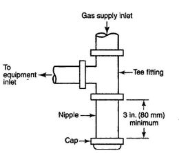
FIGURE 12-1 METHOD OF INSTALLING A TEE FITTING SEDIMENT TRAP
1213.0 Liquefied Petroleum Gas Facilities and Piping.
Liquefied petroleum gas facilities shall comply with NFPA 58, Liquefied Petroleum Gas Code.
1214.0 Pressure Testing and Inspection.
1214.1 General.
1214.1.1 Prior to acceptance and initial operation, piping installations shall be inspected and pressure-tested to determine that the materials, design, fabrication, and installation practices comply with the requirements of this code. [NFPA 54:8.1.1.1]
1214.1.2 Inspection shall consist of visual examination during or after manufacture, fabrication, assembly, or pressure tests, as appropriate. Supplementary types of non-destructive inspection techniques, such as magnetic-particle, radiographic, and ultrasonic, shall not be required unless specifically listed herein or in the engineering design. [NFPA 54:8.1.1.2]
1214.1.3 Where repairs or additions are made following the pressure test, the affected piping shall be tested. Minor repairs and additions are not required to be pressure-tested provided that the work is inspected and connections are tested with a noncorrosive leak-detecting fluid or other leak-detecting methods approved by the Authority Having Jurisdiction. [NFPA 54:8.1.1.3]
1214.1.4 Where new branches are installed from the point of delivery to new appliances, only the newly installed branches shall be required to be pressure-tested. Connections between the new piping and the existing piping shall be tested with a noncorrosive leak-detecting fluid or approved leak-detecting methods. [NFPA 54:8.1.1.4]
1214.1.5 A piping system shall be tested as a complete unit or in sections. Under no circumstances shall a valve in a line be used as a bulkhead between gas in one (1) section of the piping system and test medium in an adjacent section, unless two (2) valves are installed in series with a valved "telltale" located between these valves. A valve shall not be subjected to the test pressure unless it can be determined that the valve, including the valveclosing mechanism, is designed to safely withstand the pressure. [NFPA 54:8.1.1.5]
1214.1.6 Regulator and valve assemblies fabricated independently of the piping system in which they are to be installed shall be permitted to be tested with inert gas or air at the time of fabrication. [NFPA 54:8.1.1.6]
1214.1.7 Test Medium. The test medium shall be air, nitrogen, carbon dioxide, or an inert gas. OXYGEN SHALL NEVER BE USED. [NFPA 54:8.1.2]
1214.2 Test Preparation.
1214.2.1 Pipe joints, including welds, shall be left exposed for examination during the test. [NFPA 54:8.1.3.1]
Exception: Covered or concealed pipe end joints that have been previously tested in accordance with this code.
1214.2.2 Expansion joints shall be provided with temporary restraints, if required for the additional thrust load under test. [NFPA 54:8.1.3.2]
1214.2.3 Appliances and equipment that are not to be included in the test shall be either disconnected from the piping or isolated by blanks, blind flanges, or caps. Flanged joints at which blinds are inserted to blank off other equipment during the test shall not be required to be tested. [NFPA 54:8.1.3.3]
1214.2.4 Where the piping system is connected to appliances, equipment, or equipment components designed for operating pressures of less than the test pressure, such appliances, equipment, or equipment components shall be isolated from the piping system by disconnecting them and capping the outlets. [NFPA 54:8.1.3.4]
1214.2.5 Where the piping system is connected to appliances, equipment, or equipment components designed for operating pressures equal to or exceeding the test pressure, such appliances shall be isolated from the piping system by closing the individual appliance equipment shutoff valves. [NFPA 54:8.1.3.5]
1214.2.6 Testing of piping systems shall be done with due regard for the safety of employees and the public during the test. Bulkheads, anchorage, and bracing suitably designed to resist test pressures shall be installed if necessary. Prior to testing, the interior of the pipe shall be cleared of foreign material. [NFPA 54:8.1.3.6]
1214.3 Test Pressure.
1214.3.1 Test pressure shall be measured with a manometer or with a pressure-measuring device designed and calibrated to read, record, or indicate a pressure loss due to leakage during the pressure test period. The source of pressure shall be isolated before the pressure tests are made. Mechanical gauges used to measure test pressures shall have a range such that the highest end of the scale does not exceed five (5) times the test pressure. [NFPA 54:8.1.4.1]
1214.3.2 The test pressure to be used shall be not less than one and one-half (1½) times the proposed maximum working pressure, but not less than three (3) psi (20 kPa), irrespective of design pressure. [NFPA 54:8.1.4.2]
1214.3.3 Test duration shall be not less than one-half (½) hour for each five-hundred (500) cubic feet (14 m3) of pipe volume of fraction thereof. When testing a system having a volume less than ten (10) cubic feet (0.28 m3) or a system in a single-family dwelling, the test duration shall be not less than ten (10) minutes. The duration of the test shall not be required to exceed twenty-four (24) hours. [NFPA 54:8.1.4.3]
1214.4 Detection of Leaks and Defects.
1214.4.1 The piping system shall withstand the test pressure specified without showing any evidence of leakage or other defects. Any reduction of test pressures as indicated by pressure gauges shall be deemed to indicate the presence of a leak unless such reduction can be readily attributed to some other cause. [NFPA 54:8.1.5.1]
1214.4.2 The leakage shall be located by means of an approved gas detector, a noncorrosive leak detection fluid, or other approved leak detection methods. Matches, candles, open flames, or other methods that provide a source of ignition shall not be used. [NFPA 54:8.1.5.2]
1214.4.3 Where leakage or other defects are located, the affected portion of the piping system shall be repaired or replaced and retested [See Section 1214.1.3.]. [NFPA 54:8.1.5.3]
1214.5 Piping Systems Leak Check.
1214.5.1 Test Gases. Leak checks using fuel gas shall be permitted in piping systems that have been pressure-tested in accordance with Section 1214.0. [NFPA 54:8.2.1]
1214.5.2 Turning Gas On. During the process of turning gas on into a system of new gas piping, the entire system shall be inspected to determine that there are no open fittings or ends and that valves at unused outlets are closed and plugged or capped. [NFPA 54-09:8.2.2]
1214.5.3 Leak Check. Immediately after the gas is turned on into a new system or into a system that has been initially restored after an interruption of service, the piping system shall be checked for leakage. Where leakage is indicated, the gas supply shall be shut off until the necessary repairs have been made. [NFPA 54:8.2.3]
1214.5.4 Placing Appliance in Operation. Gas utilization appliance shall not be placed in operation until after the piping system has been tested in accordance with Section 1214.5.3 and purged in accordance with Section 1214.6.2. [NFPA 54:8.2.4]
1214.6 Purging.
1214.6.1 Removal From Service. When gas piping is to be opened for servicing, addition, or modification, the section to be worked on shall be turned off from the gas supply at the nearest convenient point and the line pressure vented to the outdoors or to ventilated areas of sufficient size to prevent accumulation of flammable mixtures. The remaining gas in this section of pipe shall be displaced with an inert gas as required by Table 12-5. [NFPA 54:8.3.1]
| NOMINAL PIPE SIZE (in.) | LENGTH OF PIPING REQUIRING PURGING (ft.) |
|---|---|
| For SI units: 1 ft. = 0.305 m. | |
| 2½ | < 50 |
| 3 | < 30 |
| 4 | < 15 |
| 6 | < 10 |
| 8 or larger | Any length |
1214.6.2 Placing in Operation. When piping full of air is placed in operation, the air in the piping shall be displaced with fuel gas, except where such piping is required by Table 12-6 to be purged with an inert gas prior to introduction of fuel gas. The air can be safely displaced with fuel gas provided that a moderately rapid and continuous flow of fuel gas is introduced at one (1) end of the line and air is vented out at the other end. The fuel gas flow shall be continued without interruption until the vented gas is free of air. The point of discharge shall not be left unattended during purging. After purging, the vent shall then be closed. Where required by Table 12-6, the air in the piping shall first be displaced with an inert gas, and the inert gas shall then be displaced with fuel gas. [NFPA 54:8.3.2]
| NOMINAL PIPE SIZE (in.) | LENGTH OF PIPING REQUIRING PURGING (ft.) |
|---|---|
| For SI units: 1 ft. = 0.305 m. | |
| 3 | < 30 |
| 4 | < 15 |
| 6 | < 10 |
| 8 or larger | Any length |
1214.6.3 Discharge of Purged Gases. The open end of piping systems being purged shall not discharge into confined spaces or areas where there are sources of ignition unless precautions are taken to perform this operation in a safe manner by ventilation of the space, control of purging rate, and elimination of hazardous conditions. [NFPA 54:8.3.3]
1214.6.4 Placing Appliances in Operation. After the piping has been placed in operation, appliances shall be purged and then placed in operation, as necessary. [NFPA 54:8.3.4]
1215.0 Interconnections Between Gas Piping Systems. [NFPA 54:5.3]
1215.1 Interconnections Supplying Separate Users. Where two (2) or more meters, or two (2) or more service regulators where meters are not provided, are located on the same premises and supply separate users, the gas-piping systems shall not be interconnected on the outlet side of the meters or service regulators. [NFPA 54:5.3.1]
1215.2 Interconnections for Standby Fuels. Where supplementary gas for standby use is connected downstream from a meter or a service regulator where a meter is not provided, a device to prevent backflow shall be installed. [NFPA 54:5.3.2.1] A three-way valve installed to admit the standby supply and at the same time shut off the regular supply shall be permitted to be used for this purpose. [NFPA 54:5.3.2.2]
1216.0 Required Gas Supply.
1216.1 The following regulations, as set forth in this section and in Section 1217.0, Required Gas Piping Size, shall be the standard for the installation of gas piping. Natural gas regulations and tables are based on the use of gas having a specific gravity of sixty-hundredths (0.60), supplied at six (6) to eight (8) inches (152–203 mm) water column pressure at the outlet of the meter or regulator. For undiluted liquefied petroleum gas, gas piping shall be permitted to be sized at eleven (11) inches (279 mm) water column pressure at the outlet of the meter or regulator and specific gravity of one and fifty- hundredths (1.50).
Note: Where gas of a different specific gravity is to be delivered, the serving gas supplier should be contacted for specific gravity conversion factors to use in sizing piping systems from the pipe sizing tables in this chapter.
1216.2 The hourly volume of gas required at each piping outlet shall be taken as not less than the maximum hourly rating as specified by the manufacturer of the appliance or appliances to be connected to each such outlet.
1216.3 Where the gas appliances to be installed have not been definitely specified, Table 12–1 shall be permitted to be used as a reference to estimate requirements of typical appliances.
To obtain the cubic feet per hour (L/sec.) of gas required, divide input of appliances by the average Btu (Watt-hour) heating value per cubic foot (L) of the gas. The average Btu (Watt-hour) per cubic foot (L) of the gas in the area of the installation shall be permitted to be obtained from the serving gas supplier.
1216.4 The size of the supply piping outlet for any gas appliance shall not be less than one-half (½) inch (15 mm).
The minimum size of any piping outlet for a mobile home shall be three-quarters (¾) of an inch (20 mm).
1217.0 Required Gas Piping Size.
1217.1 Pipe Sizing Methods. Where the pipe size is to be determined using any of the methods in Sections 1217.1.1 through 1217.1.3, the diameter of each pipe segment shall be obtained from the pipe-sizing tables in Section 1217.2 or from the sizing equations in Section 1217.3. [NFPA 54:6.1]
1217.1.1 Longest Length Method. The pipe size of each section of gas piping shall be determined using the longest length of piping from the point of delivery to the most re-
mote outlet and the load of the section (See calculation example in Figure 12–2). [NFPA 54:6.1.1]
1217.1.2 Branch Length Method. Pipe shall be sized as follows: [NFPA 54:6.1.2]
1217.1.3 Hybrid Pressure. The pipe size for each section of higher-pressure gas piping shall be determined using the longest length of piping from the point of delivery to the most remote line pressure regulator. The pipe size from the line pressure regulator to each outlet shall be determined using the length of piping from the regulator to the most remote outlet served by the regulator. [NFPA 54:6.1.3]
1217.2 Tables for Sizing Gas-Piping Systems. Tables 12–8 through 12–41 shall be used to size gas piping in conjunction with one (1) of the methods described in Sections 1217.1.1 through 1217.1.3. [NFPA 54:6.2]
1217.3 Sizing Equations. The inside diameter of smooth-wall pipe or tubing shall be determined by the sizing equations 12–1 or 12–2, using the equivalent pipe length determined by Sections 1217.1.1 through 1217.1.3. [NFPA 54:6.4]
Equation 12–1 Low-Pressure Gas Formula (Less than 1.5 psi [10.3 kPa]): [NFPA 54:6.4.1]
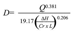
where:
D = inside diameter of pipe, inches
Q = input rate appliance(s), cubic feet per hour at 60°F (16°C) and 30-inch (759 mm) mercury column
P1 = upstream pressure, psia (P1 + 14.7)
P2 = downstream pressure, psia (P2 + 14.7)
L = equivalent length of pipe, feet
ΔH = Pressure drop, inches water column (27.7 in. H2O = 1 psi)
Equation 12–2 High-Pressure Gas Formula (1.5 psi [10.3 KPa] and above): [NFPA 54:6.4.2]
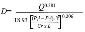
where:
D = inside diameter of pipe, inches
Q = input rate appliance(s), cubic feet per hour at 60°F (16°C) and 30-inch (759 mm) mercury column
P1 = upstream pressure, psia (P1 + 14.7)
P2 = downstream pressure, psia (P2 + 14.7)
L = equivalent length of pipe, feet
ΔH = pressure drop, inches water column (27.7 in. H2O = 1 psi)
| FORMULA FACTORS GAS | Cr | Y |
|---|---|---|
| For SI units, 1 ft.3= 0.028 m3 1 ft. = 0.305 m; 1 in. water column = 0.249 kPa; 1 psi = 6.894 kPa; 1,000 Btu/h =0.293 kW. | ||
| Natural Gas | 0.6094 | 0.9992 |
| Undiluted Propane | 1.2462 | 0.9910 |
1217.4 To determine the size of each section of pipe in any system within the range of the Table, proceed as follows:
Note: Size branch piping in the order of their distance from the meter location, beginning with the most distant outlet not previously sized.
1217.5 For conditions other than those covered by Section 1217.1, such as longer runs or greater gas demands, the size of each gas piping system shall be determined by standard engineering methods acceptable to the Authority Having Jurisdiction, and each such system shall be so designed that the total pressure drop between the meter or other point of supply and any outlet when full demand is being supplied to all outlets, shall comply with the requirements of Section 1209.4.
1217.6 Where the gas pressure exceeds fourteen (14) inches (356 mm) or less than six (6) inches (152 mm) of water column, or when diversity demand factors are used, the design, pipe, sizing, materials, location, and use of such systems first shall be approved by the Authority Having Jurisdiction. Piping systems designed for pressures exceeding the serving gas supplier's standard delivery pressure shall have prior verification from the gas supplier of the availability of the design pressure.
FIGURE 12-2 EXAMPLE ILLUSTRATING USE OF TABLES 12-1 AND 12-8
Problem: Determine the required pipe size of each section and outlet of the piping system shown in Figure 12-2, Gas to be used has a specific gravity of sixty-hundreds (0.60) and eleven-hundred (1,100) But per cubic foot (11.4 Watt-hour/L), delivered at eight (8) inch (203 mm) water column pressure.
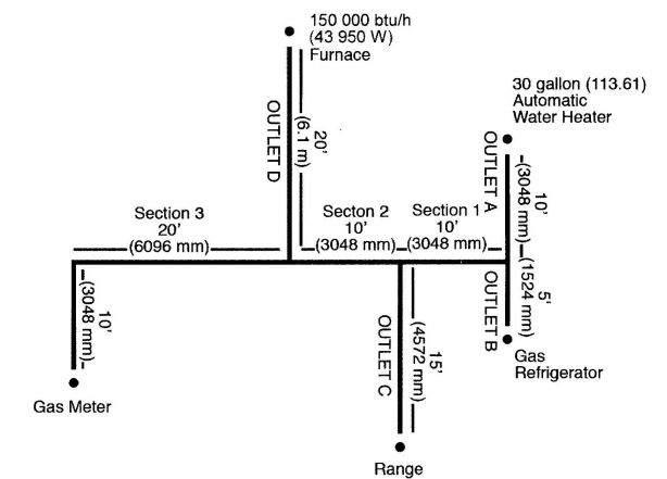
FIGURE 12-2 EXAMPLE ILLUSTRATING USE OF TABLES 12-1 AND 12-8
Solution:
| GAS: | NATURAL | |||||||||||||
|---|---|---|---|---|---|---|---|---|---|---|---|---|---|---|
| INLET PRESSURE: | LESS THAN 2 psi | |||||||||||||
| PRESSURE DROP: | 0.5 in w.c | |||||||||||||
| SPECIFIC GRAVITY: | 0.60 | |||||||||||||
| PIPE SIZE (inch) | ||||||||||||||
| NOMINAL: | ½ | ¾ | 1 | 1¼ | 1½ | 2 | 2½ | 3 | 4 | 5 | 6 | 8 | 10 | 12 |
| ACTUAL ID: | 0.622 | 0.824 | 1.049 | 1.380 | 1.610 | 2.067 | 2.469 | 3.068 | 4.026 | 5.047 | 6.065 | 7.981 | 10.020 | 11.938 |
| LENGTH (ft) | CAPACITY IN CUBIC FEET OF GAS PER HOUR | |||||||||||||
| NA means a flow of less than 10 cfh. | ||||||||||||||
| Note: All table entries are rounded to 3 significant digits. | ||||||||||||||
| 10 | 172 | 360 | 678 | 1,390 | 2,090 | 4,020 | 6,400 | 11,300 | 23,100 | 41,800 | 67,600 | 139,000 | 252,000 | 399,000 |
| 20 | 118 | 247 | 466 | 957 | 1,430 | 2,760 | 4,400 | 7,780 | 15,900 | 28,700 | 46,500 | 95,500 | 173,000 | 275,000 |
| 30 | 95 | 199 | 374 | 768 | 1,150 | 2,220 | 3,530 | 6,250 | 12,700 | 23,000 | 37,300 | 76,700 | 139,000 | 220,000 |
| 40 | 81 | 170 | 320 | 657 | 985 | 1,900 | 3,020 | 5,350 | 10,900 | 19,700 | 31,900 | 65,600 | 119,000 | 189,000 |
| 50 | 72 | 151 | 284 | 583 | 873 | 1,680 | 2,680 | 4,740 | 9,660 | 17,500 | 28,300 | 58,200 | 106,000 | 167,000 |
| 60 | 65 | 137 | 257 | 528 | 791 | 1,520 | 2,430 | 4,290 | 8,760 | 15,800 | 25,600 | 52,700 | 95,700 | 152,000 |
| 70 | 60 | 126 | 237 | 486 | 728 | 1,400 | 2,230 | 3,950 | 8,050 | 14,600 | 23,600 | 48,500 | 88,100 | 139,000 |
| 80 | 56 | 117 | 220 | 452 | 677 | 1,300 | 2,080 | 3,670 | 7,490 | 13,600 | 22,000 | 45,100 | 81,900 | 130,000 |
| 90 | 52 | 110 | 207 | 424 | 635 | 1,220 | 1,950 | 3,450 | 7,030 | 12,700 | 20,600 | 42,300 | 76,900 | 122,000 |
| 100 | 50 | 104 | 195 | 400 | 600 | 1,160 | 1,840 | 3,260 | 6,640 | 12,000 | 19,500 | 40,000 | 72,600 | 115,000 |
| 125 | 44 | 92 | 173 | 355 | 532 | 1,020 | 1,630 | 2,890 | 5,890 | 10,600 | 17,200 | 35,400 | 64,300 | 102,000 |
| 150 | 40 | 83 | 157 | 322 | 482 | 928 | 1,480 | 2,610 | 5,330 | 9,650 | 15,600 | 32,100 | 58,300 | 92,300 |
| 175 | 37 | 77 | 144 | 296 | 443 | 854 | 1,360 | 2,410 | 4,910 | 8,880 | 14,400 | 29,500 | 53,600 | 84,900 |
| 200 | 34 | 71 | 134 | 275 | 412 | 794 | 1,270 | 2,240 | 4,560 | 8,260 | 13,400 | 27,500 | 49,900 | 79,000 |
| 250 | 30 | 63 | 119 | 244 | 366 | 704 | 1,120 | 1,980 | 4,050 | 7,320 | 11,900 | 24,300 | 44,200 | 70,000 |
| 300 | 27 | 57 | 108 | 221 | 331 | 638 | 1,020 | 1,800 | 3,670 | 6,630 | 10,700 | 22,100 | 40,100 | 63,400 |
| 350 | 25 | 53 | 99 | 203 | 305 | 587 | 935 | 1,650 | 3,370 | 6,100 | 9,880 | 20,300 | 36,900 | 58,400 |
| 400 | 23 | 49 | 92 | 189 | 283 | 546 | 870 | 1,540 | 3,140 | 5,680 | 9,190 | 18,900 | 34,300 | 54,300 |
| 450 | 22 | 46 | 86 | 177 | 266 | 512 | 816 | 1,440 | 2,940 | 5,330 | 8,620 | 17,700 | 32,200 | 50,900 |
| 500 | 21 | 43 | 82 | 168 | 251 | 484 | 771 | 1,360 | 2,780 | 5,030 | 8,150 | 16,700 | 30,400 | 48,100 |
| 550 | 20 | 41 | 78 | 159 | 239 | 459 | 732 | 1,290 | 2,640 | 4,780 | 7,740 | 15,900 | 28,900 | 45,700 |
| 600 | 19 | 39 | 74 | 152 | 228 | 438 | 699 | 1,240 | 2,520 | 4,560 | 7,380 | 15,200 | 27,500 | 43,600 |
| 650 | 18 | 38 | 71 | 145 | 218 | 420 | 669 | 1,180 | 2,410 | 4,360 | 7,070 | 14,500 | 26,400 | 41,800 |
| 700 | 17 | 36 | 68 | 140 | 209 | 403 | 643 | 1,140 | 2,320 | 4,190 | 6,790 | 14,000 | 25,300 | 40,100 |
| 750 | 17 | 35 | 66 | 135 | 202 | 389 | 619 | 1,090 | 2,230 | 4,040 | 6,540 | 13,400 | 24,400 | 38,600 |
| 800 | 16 | 34 | 63 | 130 | 195 | 375 | 598 | 1,060 | 2,160 | 3,900 | 6,320 | 13,000 | 23,600 | 37,300 |
| 850 | 16 | 33 | 61 | 126 | 189 | 363 | 579 | 1,020 | 2,090 | 3,780 | 6,110 | 12,600 | 22,800 | 36,100 |
| 900 | 15 | 32 | 59 | 122 | 183 | 352 | 561 | 992 | 2,020 | 3,660 | 5,930 | 12,200 | 22,100 | 35,000 |
| 950 | 15 | 31 | 58 | 118 | 178 | 342 | 545 | 963 | 1,960 | 3,550 | 5,760 | 11,800 | 21,500 | 34,000 |
| 1,000 | 14 | 30 | 56 | 115 | 173 | 333 | 530 | 937 | 1,910 | 3,460 | 5,600 | 11,500 | 20,900 | 33,100 |
| 1,100 | 14 | 28 | 53 | 109 | 164 | 316 | 503 | 890 | 1,810 | 3,280 | 5,320 | 10,900 | 19,800 | 31,400 |
| 1,200 | 13 | 27 | 51 | 104 | 156 | 301 | 480 | 849 | 1,730 | 3,130 | 5,070 | 10,400 | 18,900 | 30,000 |
| 1,300 | 12 | 26 | 49 | 100 | 150 | 289 | 460 | 813 | 1,660 | 3,000 | 4,860 | 9,980 | 18,100 | 28,700 |
| 1,400 | 12 | 25 | 47 | 96 | 144 | 277 | 442 | 781 | 1,590 | 2,880 | 4,670 | 9,590 | 17,400 | 27,600 |
| 1,500 | 11 | 24 | 45 | 93 | 139 | 267 | 426 | 752 | 1,530 | 2,780 | 4,500 | 9,240 | 16,800 | 26,600 |
| 1,600 | 11 | 23 | 44 | 89 | 134 | 258 | 411 | 727 | 1,480 | 2,680 | 4,340 | 8,920 | 16,200 | 25,600 |
| 1,700 | 11 | 22 | 42 | 86 | 130 | 250 | 398 | 703 | 1,430 | 2,590 | 4,200 | 8,630 | 15,700 | 24,800 |
| 1,800 | 10 | 22 | 41 | 84 | 126 | 242 | 386 | 682 | 1,390 | 2,520 | 4,070 | 8,370 | 15,200 | 24,100 |
| 1,900 | 10 | 21 | 40 | 81 | 122 | 235 | 375 | 662 | 1,350 | 2,440 | 3,960 | 8,130 | 14,800 | 23,400 |
| 2,000 | NA | 20 | 39 | 79 | 119 | 229 | 364 | 644 | 1,310 | 2,380 | 3,850 | 7,910 | 14,400 | 22,700 |
| GAS: | NATURAL | |||||||||
|---|---|---|---|---|---|---|---|---|---|---|
| INLET PRESSURE: | 2.0 psi | |||||||||
| PRESSURE DROP: | 1.0 psi | |||||||||
| SPECIFIC GRAVITY: | 0.60 | |||||||||
| PIPE SIZE (inch) | ||||||||||
| NOMINAL: | ½ | ¾ | 1 | 1¼ | 1½ | 2 | 2½ | 3 | 4 | |
| ACTUAL ID: | 0.622 | 0.824 | 1.049 | 1.380 | 1.610 | 2.067 | 2.469 | 3.068 | 4.026 | |
| LENGTH (ft.) | CAPACITY IN CUBIC FEET OF GAS PER HOUR | |||||||||
| Note: All table entries are rounded to 3 significant digits. | ||||||||||
| 10 | 1,510 | 3,040 | 5,560 | 11,400 | 17,100 | 32,900 | 52,500 | 92,800 | 189,000 | |
| 20 | 1,070 | 2,150 | 3,930 | 8,070 | 12,100 | 23,300 | 37,100 | 65,600 | 134,000 | |
| 30 | 869 | 1,760 | 3,210 | 6,590 | 9,880 | 19,000 | 30,300 | 53,600 | 109,000 | |
| 40 | 753 | 1,520 | 2,780 | 5,710 | 8,550 | 16,500 | 26,300 | 46,400 | 94,700 | |
| 50 | 673 | 1,360 | 2,490 | 5,110 | 7,650 | 14,700 | 23,500 | 41,500 | 84,700 | |
| 60 | 615 | 1,240 | 2,270 | 4,660 | 6,980 | 13,500 | 21,400 | 37,900 | 77,300 | |
| 70 | 569 | 1,150 | 2,100 | 4,320 | 6,470 | 12,500 | 19,900 | 35,100 | 71,600 | |
| 80 | 532 | 1,080 | 1,970 | 4,040 | 6,050 | 11,700 | 18,600 | 32,800 | 67,000 | |
| 90 | 502 | 1,010 | 1,850 | 3,810 | 5,700 | 11,000 | 17,500 | 30,900 | 63,100 | |
| 100 | 462 | 934 | 1,710 | 3,510 | 5,260 | 10,100 | 16,100 | 28,500 | 58,200 | |
| 125 | 414 | 836 | 1,530 | 3,140 | 4,700 | 9,060 | 14,400 | 25,500 | 52,100 | |
| 150 | 372 | 751 | 1,370 | 2,820 | 4,220 | 8,130 | 13,000 | 22,900 | 46,700 | |
| 175 | 344 | 695 | 1,270 | 2,601 | 3,910 | 7,530 | 12,000 | 21,200 | 43,300 | |
| 200 | 318 | 642 | 1,170 | 2,410 | 3,610 | 6,960 | 11,100 | 19,600 | 40,000 | |
| 250 | 279 | 583 | 1,040 | 2,140 | 3,210 | 6,180 | 9,850 | 17,400 | 35,500 | |
| 300 | 253 | 528 | 945 | 1,940 | 2,910 | 5,600 | 8,920 | 15,800 | 32,200 | |
| 350 | 232 | 486 | 869 | 1,790 | 2,670 | 5,150 | 8,210 | 14,500 | 29,600 | |
| 400 | 216 | 452 | 809 | 1,660 | 2,490 | 4,790 | 7,640 | 13,500 | 27,500 | |
| 450 | 203 | 424 | 759 | 1,560 | 2,330 | 4,500 | 7,170 | 12,700 | 25,800 | |
| 500 | 192 | 401 | 717 | 1,470 | 2,210 | 4,250 | 6,770 | 12,000 | 24,400 | |
| 550 | 182 | 381 | 681 | 1,400 | 2,090 | 4,030 | 6,430 | 11,400 | 23,200 | |
| 600 | 174 | 363 | 650 | 1,330 | 2,000 | 3,850 | 6,130 | 10,800 | 22,100 | |
| 650 | 166 | 348 | 622 | 1,280 | 1,910 | 3,680 | 5,870 | 10,400 | 21,200 | |
| 700 | 160 | 334 | 598 | 1,230 | 1,840 | 3,540 | 5,640 | 9,970 | 20,300 | |
| 750 | 154 | 322 | 576 | 1,180 | 1,770 | 3,410 | 5,440 | 9,610 | 19,600 | |
| 800 | 149 | 311 | 556 | 1,140 | 1,710 | 3,290 | 5,250 | 9,280 | 18,900 | |
| 850 | 144 | 301 | 538 | 1,100 | 1,650 | 3,190 | 5,080 | 8,980 | 18,300 | |
| 900 | 139 | 292 | 522 | 1,070 | 1,600 | 3,090 | 4,930 | 8,710 | 17,800 | |
| 950 | 135 | 283 | 507 | 1,040 | 1,560 | 3,000 | 4,780 | 8,460 | 17,200 | |
| 1,000 | 132 | 275 | 493 | 1,010 | 1,520 | 2,920 | 4,650 | 8,220 | 16,800 | |
| 1,100 | 125 | 262 | 468 | 960 | 1,440 | 2,770 | 4,420 | 7,810 | 15,900 | |
| 1,200 | 119 | 250 | 446 | 917 | 1,370 | 2,640 | 4,220 | 7,450 | 15,200 | |
| 1,300 | 114 | 239 | 427 | 878 | 1,320 | 2,530 | 4,040 | 7,140 | 14,600 | |
| 1,400 | 110 | 230 | 411 | 843 | 1,260 | 2,430 | 3,880 | 6,860 | 14,000 | |
| 1,500 | 106 | 221 | 396 | 812 | 1,220 | 2,340 | 3,740 | 6,600 | 13,500 | |
| 1,600 | 102 | 214 | 382 | 784 | 1,180 | 2,260 | 3,610 | 6,380 | 13,000 | |
| 1,700 | 99 | 207 | 370 | 759 | 1,140 | 2,190 | 3,490 | 6,170 | 12,600 | |
| 1,800 | 96 | 200 | 358 | 736 | 1,100 | 2,120 | 3,390 | 5,980 | 12,200 | |
| 1,900 | 93 | 195 | 348 | 715 | 1,070 | 2,060 | 3,290 | 5,810 | 11,900 | |
| 2,000 | 91 | 189 | 339 | 695 | 1,040 | 2,010 | 3,200 | 5,650 | 11,500 | |
| GAS: | NATURAL | |||||||||
|---|---|---|---|---|---|---|---|---|---|---|
| INLET PRESSURE: | 3.0 psi | |||||||||
| PRESSURE DROP: | 2.0 psi | |||||||||
| SPECIFIC GRAVITY: | 0.60 | |||||||||
| PIPE SIZE (inch) | ||||||||||
| NOMINAL: | ½ | ¾ | 1 | 1¼ | 1½ | 2 | 2½ | 3 | 4 | |
| ACTUAL ID: | 0.622 | 0.824 | 1.049 | 1.380 | 1.610 | 2.067 | 2.469 | 3.068 | 4.026 | |
| LENGTH (ft.) | CAPACITY IN CUBIC FEET OF GAS PER HOUR | |||||||||
| Note: All table entries are rounded to 3 significant digits | ||||||||||
| 10 | 2,350 | 4,920 | 9,270 | 19,000 | 28,500 | 54,900 | 87,500 | 155,000 | 316,000 | |
| 20 | 1,620 | 3,380 | 6,370 | 13,100 | 19,600 | 37,700 | 60,100 | 106,000 | 217,000 | |
| 30 | 1,300 | 2,720 | 5,110 | 10,500 | 15,700 | 30,300 | 48,300 | 85,400 | 174,000 | |
| 40 | 1,110 | 2,320 | 4,380 | 8,990 | 13,500 | 25,900 | 41,300 | 73,100 | 149,000 | |
| 50 | 985 | 2,060 | 3,880 | 7,970 | 11,900 | 23,000 | 36,600 | 64,800 | 132,000 | |
| 60 | 892 | 1,870 | 3,520 | 7,220 | 10,800 | 20,800 | 33,200 | 58,700 | 120,000 | |
| 70 | 821 | 1,720 | 3,230 | 6,640 | 9,950 | 19,200 | 30,500 | 54,000 | 110,000 | |
| 80 | 764 | 1,600 | 3,010 | 6,180 | 9,260 | 17,800 | 28,400 | 50,200 | 102,000 | |
| 90 | 717 | 1,500 | 2,820 | 5,800 | 8,680 | 16,700 | 26,700 | 47,100 | 96,100 | |
| 100 | 677 | 1,420 | 2,670 | 5,470 | 8,200 | 15,800 | 25,200 | 44,500 | 90,800 | |
| 125 | 600 | 1,250 | 2,360 | 4,850 | 7,270 | 14,000 | 22,300 | 39,500 | 80,500 | |
| 150 | 544 | 1,140 | 2,140 | 4,400 | 6,590 | 12,700 | 20,200 | 35,700 | 72,900 | |
| 175 | 500 | 1,050 | 1,970 | 4,040 | 6,060 | 11,700 | 18,600 | 32,900 | 67,100 | |
| 200 | 465 | 973 | 1,830 | 3,760 | 5,640 | 10,900 | 17,300 | 30,600 | 62,400 | |
| 250 | 412 | 862 | 1,620 | 3,330 | 5,000 | 9,620 | 15,300 | 27,100 | 55,300 | |
| 300 | 374 | 781 | 1,470 | 3,020 | 4,530 | 8,720 | 13,900 | 24,600 | 50,100 | |
| 350 | 344 | 719 | 1,350 | 2,780 | 4,170 | 8,020 | 12,800 | 22,600 | 46,100 | |
| 400 | 320 | 669 | 1,260 | 2,590 | 3,870 | 7,460 | 11,900 | 21,000 | 42,900 | |
| 450 | 300 | 627 | 1,180 | 2,430 | 3,640 | 7,000 | 11,200 | 19,700 | 40,200 | |
| 500 | 283 | 593 | 1,120 | 2,290 | 3,430 | 6,610 | 10,500 | 18,600 | 38,000 | |
| 550 | 269 | 563 | 1,060 | 2,180 | 3,260 | 6,280 | 10,000 | 17,700 | 36,100 | |
| 600 | 257 | 537 | 1,010 | 2,080 | 3,110 | 5,990 | 9,550 | 16,900 | 34,400 | |
| 650 | 246 | 514 | 969 | 1,990 | 2,980 | 5,740 | 9,150 | 16,200 | 33,000 | |
| 700 | 236 | 494 | 931 | 1,910 | 2,860 | 5,510 | 8,790 | 15,500 | 31,700 | |
| 750 | 228 | 476 | 897 | 1,840 | 2,760 | 5,310 | 8,470 | 15,000 | 30,500 | |
| 800 | 220 | 460 | 866 | 1,780 | 2,660 | 5,130 | 8,180 | 14,500 | 29,500 | |
| 850 | 213 | 445 | 838 | 1,720 | 2,580 | 4,960 | 7,910 | 14,000 | 28,500 | |
| 900 | 206 | 431 | 812 | 1,670 | 2,500 | 4,810 | 7,670 | 13,600 | 27,700 | |
| 950 | 200 | 419 | 789 | 1,620 | 2,430 | 4,670 | 7,450 | 13,200 | 26,900 | |
| 1,000 | 195 | 407 | 767 | 1,580 | 2,360 | 4,550 | 7,240 | 12,800 | 26,100 | |
| 1,100 | 185 | 387 | 729 | 1,500 | 2,240 | 4,320 | 6,890 | 12,200 | 24,800 | |
| 1,200 | 177 | 369 | 695 | 1,430 | 2,140 | 4,120 | 6,570 | 11,600 | 23,700 | |
| 1,300 | 169 | 353 | 666 | 1,370 | 2,050 | 3,940 | 6,290 | 11,100 | 22,700 | |
| 1,400 | 162 | 340 | 640 | 1,310 | 1,970 | 3,790 | 6,040 | 10,700 | 21,800 | |
| 1,500 | 156 | 327 | 616 | 1,270 | 1,900 | 3,650 | 5,820 | 10,300 | 21,000 | |
| 1,600 | 151 | 316 | 595 | 1,220 | 1,830 | 3,530 | 5,620 | 10,000 | 20,300 | |
| 1,700 | 146 | 306 | 576 | 1,180 | 1,770 | 3,410 | 5,440 | 9,610 | 19,600 | |
| 1,800 | 142 | 296 | 558 | 1,150 | 1,720 | 3,310 | 5,270 | 9,320 | 19,000 | |
| 1,900 | 138 | 288 | 542 | 1,110 | 1,670 | 3,210 | 5,120 | 9,050 | 18,400 | |
| 2,000 | 134 | 280 | 527 | 1,080 | 1,620 | 3,120 | 4,980 | 8,800 | 18,000 | |
| GAS: | NATURAL | |||||||||
|---|---|---|---|---|---|---|---|---|---|---|
| INLET PRESSURE: | 5.0 psi | |||||||||
| PRESSURE DROP: | 3.5 psi | |||||||||
| SPECIFIC GRAVITY: | 0.60 | |||||||||
| PIPE SIZE (inch) | ||||||||||
| NOMINAL: | ½ | ¾ | 1 | 1¼ | 1½ | 2 | 2½ | 3 | 4 | |
| ACTUAL ID: | 0.622 | 0.824 | 1.049 | 1.380 | 1.610 | 2.067 | 2.469 | 3.068 | 4.026 | |
| LENGTH (ft.) | CAPACITY IN CUBIC FEET OF GAS PER HOUR | |||||||||
| Note: All table entries are rounded to 3 significant digits. | ||||||||||
| 10 | 3,190 | 6,430 | 11,800 | 24,200 | 36,200 | 69,700 | 111,000 | 196,000 | 401,000 | |
| 20 | 2,250 | 4,550 | 8,320 | 17,100 | 25,600 | 49,300 | 78,600 | 139,000 | 283,000 | |
| 30 | 1,840 | 3,720 | 6,790 | 14,000 | 20,900 | 40,300 | 64,200 | 113,000 | 231,000 | |
| 40 | 1,590 | 3,220 | 5,880 | 12,100 | 18,100 | 34,900 | 55,600 | 98,200 | 200,000 | |
| 50 | 1,430 | 2,880 | 5,260 | 10,800 | 16,200 | 31,200 | 49,700 | 87,900 | 179,000 | |
| 60 | 1,300 | 2,630 | 4,800 | 9,860 | 14,800 | 28,500 | 45,400 | 80,200 | 164,000 | |
| 70 | 1,200 | 2,430 | 4,450 | 9,130 | 13,700 | 26,400 | 42,000 | 74,300 | 151,000 | |
| 80 | 1,150 | 2,330 | 4,260 | 8,540 | 12,800 | 24,700 | 39,300 | 69,500 | 142,000 | |
| 90 | 1,060 | 2,150 | 3,920 | 8,050 | 12,100 | 23,200 | 37,000 | 65,500 | 134,000 | |
| 100 | 979 | 1,980 | 3,620 | 7,430 | 11,100 | 21,400 | 34,200 | 60,400 | 123,000 | |
| 125 | 876 | 1,770 | 3,240 | 6,640 | 9,950 | 19,200 | 30,600 | 54,000 | 110,000 | |
| 150 | 786 | 1,590 | 2,910 | 5,960 | 8,940 | 17,200 | 27,400 | 48,500 | 98,900 | |
| 175 | 728 | 1,470 | 2,690 | 5,520 | 8,270 | 15,900 | 25,400 | 44,900 | 91,600 | |
| 200 | 673 | 1,360 | 2,490 | 5,100 | 7,650 | 14,700 | 23,500 | 41,500 | 84,700 | |
| 250 | 558 | 1,170 | 2,200 | 4,510 | 6,760 | 13,000 | 20,800 | 36,700 | 74,900 | |
| 300 | 506 | 1,060 | 1,990 | 4,090 | 6,130 | 11,800 | 18,800 | 33,300 | 67,800 | |
| 350 | 465 | 973 | 1,830 | 3,760 | 5,640 | 10,900 | 17,300 | 30,600 | 62,400 | |
| 400 | 433 | 905 | 1,710 | 3,500 | 5,250 | 10,100 | 16,100 | 28,500 | 58,100 | |
| 450 | 406 | 849 | 1,600 | 3,290 | 4,920 | 9,480 | 15,100 | 26,700 | 54,500 | |
| 500 | 384 | 802 | 1,510 | 3,100 | 4,650 | 8,950 | 14,300 | 25,200 | 51,500 | |
| 550 | 364 | 762 | 1,440 | 2,950 | 4,420 | 8,500 | 13,600 | 24,000 | 48,900 | |
| 600 | 348 | 727 | 1,370 | 2,810 | 4,210 | 8,110 | 12,900 | 22,900 | 46,600 | |
| 650 | 333 | 696 | 1,310 | 2,690 | 4,030 | 7,770 | 12,400 | 21,900 | 44,600 | |
| 700 | 320 | 669 | 1,260 | 2,590 | 3,880 | 7,460 | 11,900 | 21,000 | 42,900 | |
| 750 | 308 | 644 | 1,210 | 2,490 | 3,730 | 7,190 | 11,500 | 20,300 | 41,300 | |
| 800 | 298 | 622 | 1,170 | 2,410 | 3,610 | 6,940 | 11,100 | 19,600 | 39,900 | |
| 850 | 288 | 602 | 1,130 | 2,330 | 3,490 | 6,720 | 10,700 | 18,900 | 38,600 | |
| 900 | 279 | 584 | 1,100 | 2,260 | 3,380 | 6,520 | 10,400 | 18,400 | 37,400 | |
| 950 | 271 | 567 | 1,070 | 2,190 | 3,290 | 6,330 | 10,100 | 17,800 | 36,400 | |
| 1,000 | 264 | 551 | 1,040 | 2,130 | 3,200 | 6,150 | 9,810 | 17,300 | 35,400 | |
| 1,100 | 250 | 524 | 987 | 2,030 | 3,030 | 5,840 | 9,320 | 16,500 | 33,600 | |
| 1,200 | 239 | 500 | 941 | 1,930 | 2,900 | 5,580 | 8,890 | 15,700 | 32,000 | |
| 1,300 | 229 | 478 | 901 | 1,850 | 2,770 | 5,340 | 8,510 | 15,000 | 30,700 | |
| 1,400 | 220 | 460 | 866 | 1,780 | 2,660 | 5,130 | 8,180 | 14,500 | 29,500 | |
| 1,500 | 212 | 443 | 834 | 1,710 | 2,570 | 4,940 | 7,880 | 13,900 | 28,400 | |
| 1,600 | 205 | 428 | 806 | 1,650 | 2,480 | 4,770 | 7,610 | 13,400 | 27,400 | |
| 1,700 | 198 | 414 | 780 | 1,600 | 2,400 | 4,620 | 7,360 | 13,000 | 26,500 | |
| 1,800 | 192 | 401 | 756 | 1,550 | 2,330 | 4,480 | 7,140 | 12,600 | 25,700 | |
| 1,900 | 186 | 390 | 734 | 1,510 | 2,260 | 4,350 | 6,930 | 12,300 | 25,000 | |
| 2,000 | 181 | 379 | 714 | 1,470 | 2,200 | 4,230 | 6,740 | 11,900 | 24,300 | |
| GAS: | NATURAL | |||||||||
|---|---|---|---|---|---|---|---|---|---|---|
| INLET PRESSURE: | LESS THAN 2 psi | |||||||||
| PRESSURE DROP: | 0.3 in. w.c. | |||||||||
| SPECIFIC GRAVITY: | 0.60 | |||||||||
| TUBE SIZE (inch) | ||||||||||
| NOMINAL: | K ' L: | ¼ | 3/8 | ½ | 5/8 | ¾ | 1 | 1¼ | 1½ | 2 |
| ACR: | 3/8 | ½ | 5/8 | ¾ | 7/8 | 11/8; | 13/8; | - | - | |
| OUTSIDE: | 0.375 | 0.500 | 0.625 | 0.750 | 0.875 | 1.125 | 1.375 | 1.625 | 2.125 | |
| INSIDE:* | 0.305 | 0.402 | 0.527 | 0.652 | 0.745 | 0.995 | 1.245 | 1.481 | 1.959 | |
| LENGTH (ft.) | CAPACITY IN CUBIC FEET OF GAS PER HOUR | |||||||||
| NA means a flow of less than 10 cfh. | ||||||||||
| Note: All table entries are rounded to 3 significant digits. | ||||||||||
| *Table capacities are based on Type K copper tubing inside diameter (shown), which has the smallest inside diameter of the copper tubing products. | ||||||||||
| 10 | 20 | 42 | 85 | 148 | 210 | 448 | 806 | 1,270 | 2,650 | |
| 20 | 14 | 29 | 58 | 102 | 144 | 308 | 554 | 873 | 1,820 | |
| 30 | 11 | 23 | 47 | 82 | 116 | 247 | 445 | 701 | 1,460 | |
| 40 | 10 | 20 | 40 | 70 | 99 | 211 | 381 | 600 | 1,250 | |
| 50 | NA | 17 | 35 | 62 | 88 | 187 | 337 | 532 | 1,110 | |
| 60 | NA | 16 | 32 | 56 | 79 | 170 | 306 | 482 | 1,000 | |
| 70 | NA | 14 | 29 | 52 | 73 | 156 | 281 | 443 | 924 | |
| 80 | NA | 13 | 27 | 48 | 68 | 145 | 262 | 413 | 859 | |
| 90 | NA | 13 | 26 | 45 | 64 | 136 | 245 | 387 | 806 | |
| 100 | NA | 12 | 24 | 43 | 60 | 129 | 232 | 366 | 761 | |
| 125 | NA | 11 | 22 | 38 | 53 | 114 | 206 | 324 | 675 | |
| 150 | NA | 10 | 20 | 34 | 48 | 103 | 186 | 294 | 612 | |
| 175 | NA | NA | 18 | 31 | 48 | 95 | 171 | 270 | 563 | |
| 200 | NA | NA | 17 | 29 | 41 | 89 | 159 | 251 | 523 | |
| 250 | NA | NA | 15 | 26 | 37 | 78 | 141 | 223 | 464 | |
| 300 | NA | NA | 13 | 23 | 33 | 71 | 128 | 202 | 420 | |
| 350 | NA | NA | 12 | 22 | 31 | 65 | 118 | 186 | 387 | |
| 400 | NA | NA | 11 | 20 | 28 | 61 | 110 | 173 | 360 | |
| 450 | NA | NA | 11 | 19 | 27 | 57 | 103 | 162 | 338 | |
| 500 | NA | NA | 10 | 18 | 25 | 54 | 97 | 153 | 319 | |
| 550 | NA | NA | NA | 17 | 24 | 51 | 92 | 145 | 303 | |
| 600 | NA | NA | NA | 16 | 23 | 49 | 88 | 139 | 289 | |
| 650 | NA | NA | NA | 15 | 22 | 47 | 84 | 133 | 277 | |
| 700 | NA | NA | NA | 15 | 21 | 45 | 81 | 128 | 266 | |
| 750 | NA | NA | NA | 14 | 20 | 43 | 78 | 123 | 256 | |
| 800 | NA | NA | NA | 14 | 20 | 42 | 75 | 119 | 247 | |
| 850 | NA | NA | NA | 13 | 19 | 40 | 73 | 115 | 239 | |
| 900 | NA | NA | NA | 13 | 18 | 39 | 71 | 111 | 232 | |
| 950 | NA | NA | NA | 13 | 18 | 38 | 69 | 108 | 225 | |
| 1,000 | NA | NA | NA | 12 | 17 | 37 | 67 | 105 | 219 | |
| 1,100 | NA | NA | NA | 12 | 16 | 35 | 63 | 100 | 208 | |
| 1,200 | NA | NA | NA | 11 | 16 | 34 | 60 | 95 | 199 | |
| 1,300 | NA | NA | NA | 11 | 15 | 32 | 58 | 91 | 190 | |
| 1,400 | NA | NA | NA | 10 | 14 | 31 | 56 | 88 | 183 | |
| 1,500 | NA | NA | NA | NA | 14 | 30 | 54 | 84 | 176 | |
| 1,600 | NA | NA | NA | NA | 13 | 29 | 52 | 82 | 170 | |
| 1,700 | NA | NA | NA | NA | 13 | 28 | 50 | 79 | 164 | |
| 1,800 | NA | NA | NA | NA | 13 | 27 | 49 | 77 | 159 | |
| 1,900 | NA | NA | NA | NA | 12 | 26 | 47 | 74 | 155 | |
| 2,000 | NA | NA | NA | NA | 12 | 25 | 46 | 72 | 151 | |
| GAS: | NATURAL | |||||||||
|---|---|---|---|---|---|---|---|---|---|---|
| INLET PRESSURE: | LESS THAN 2 psi | |||||||||
| PRESSURE DROP: | 0.5 in. w.c. | |||||||||
| SPECIFIC GRAVITY: | 0.60 | |||||||||
| TUBE SIZE (inch) | ||||||||||
| NOMINAL: | K & L: | ¼ | 3/8 | ½ | 5/8 | ¾ | 1 | 1¼ | 1½ | 2 |
| ACR: | 3/8 | ½ | 5/8 | ¾ | 7/8 | 11/8 | 13/8 | - | - | |
| OUTSIDE: | 0.375 | 0.500 | 0.625 | 0.750 | 0.875 | 1.125 | 1.375 | 1.625 | 2.125 | |
| INSIDE:* | 0.305 | 0.402 | 0.527 | 0.652 | 0.745 | 0.995 | 1.245 | 1.481 | 1.959 | |
| LENGTH (ft.) | CAPACITY IN CUBIC FEET OF GAS PER HOUR | |||||||||
| NA means a flow of less than 10 cfh. | ||||||||||
| Note: All table entries are rounded to 3 significant digits. | ||||||||||
| *Table capacities are based on Type K copper tubing inside diameter (shown), which has the smallest inside diameter of the copper tubing products. | ||||||||||
| 10 | 27 | 55 | 111 | 195 | 276 | 590 | 1,060 | 1,680 | 3,490 | |
| 20 | 18 | 38 | 77 | 134 | 190 | 406 | 730 | 1,150 | 2,400 | |
| 30 | 15 | 30 | 61 | 107 | 152 | 326 | 586 | 925 | 1,930 | |
| 40 | 13 | 26 | 53 | 92 | 131 | 279 | 502 | 791 | 1,650 | |
| 50 | 11 | 23 | 47 | 82 | 116 | 247 | 445 | 701 | 1,460 | |
| 60 | 10 | 21 | 42 | 74 | 105 | 224 | 403 | 635 | 1,320 | |
| 70 | NA | 19 | 39 | 68 | 96 | 206 | 371 | 585 | 1,220 | |
| 80 | NA | 18 | 36 | 63 | 90 | 192 | 345 | 544 | 1,130 | |
| 90 | NA | 17 | 34 | 59 | 84 | 180 | 324 | 510 | 1,060 | |
| 100 | NA | 16 | 32 | 56 | 79 | 170 | 306 | 482 | 1,000 | |
| 125 | NA | 14 | 28 | 50 | 70 | 151 | 271 | 427 | 890 | |
| 150 | NA | 13 | 26 | 45 | 64 | 136 | 245 | 387 | 806 | |
| 175 | NA | 12 | 24 | 41 | 59 | 125 | 226 | 356 | 742 | |
| 200 | NA | 11 | 22 | 39 | 55 | 117 | 210 | 331 | 690 | |
| 250 | NA | NA | 20 | 34 | 48 | 103 | 186 | 294 | 612 | |
| 300 | NA | NA | 18 | 31 | 44 | 94 | 169 | 266 | 554 | |
| 350 | NA | NA | 16 | 28 | 40 | 86 | 155 | 245 | 510 | |
| 400 | NA | NA | 15 | 26 | 38 | 80 | 144 | 228 | 474 | |
| 450 | NA | NA | 14 | 25 | 35 | 75 | 135 | 214 | 445 | |
| 500 | NA | NA | 13 | 23 | 33 | 71 | 128 | 202 | 420 | |
| 550 | NA | NA | 13 | 22 | 32 | 68 | 122 | 192 | 399 | |
| 600 | NA | NA | 12 | 21 | 30 | 64 | 116 | 183 | 381 | |
| 650 | NA | NA | 12 | 20 | 29 | 62 | 111 | 175 | 365 | |
| 700 | NA | NA | 11 | 20 | 28 | 59 | 107 | 168 | 350 | |
| 750 | NA | NA | 11 | 19 | 27 | 57 | 103 | 162 | 338 | |
| 800 | NA | NA | 10 | 18 | 26 | 55 | 99 | 156 | 326 | |
| 850 | NA | NA | 10 | 18 | 25 | 53 | 96 | 151 | 315 | |
| 900 | NA | NA | NA | 17 | 24 | 52 | 93 | 147 | 306 | |
| 950 | NA | NA | NA | 17 | 24 | 50 | 90 | 143 | 297 | |
| 1,000 | NA | NA | NA | 16 | 23 | 49 | 88 | 139 | 289 | |
| 1,100 | NA | NA | NA | 15 | 22 | 46 | 84 | 132 | 274 | |
| 1,200 | NA | NA | NA | 15 | 21 | 44 | 80 | 126 | 262 | |
| 1,300 | NA | NA | NA | 14 | 20 | 42 | 76 | 120 | 251 | |
| 1,400 | NA | NA | NA | 13 | 19 | 41 | 73 | 116 | 241 | |
| 1,500 | NA | NA | NA | 13 | 18 | 39 | 71 | 111 | 232 | |
| 1,600 | NA | NA | NA | 13 | 18 | 38 | 68 | 108 | 224 | |
| 1,700 | NA | NA | NA | 12 | 17 | 37 | 66 | 104 | 217 | |
| 1,800 | NA | NA | NA | 12 | 17 | 36 | 64 | 101 | 210 | |
| 1,900 | NA | NA | NA | 11 | 16 | 35 | 62 | 98 | 204 | |
| 2,000 | NA | NA | NA | 11 | 16 | 34 | 60 | 95 | 199 | |
| GAS: | NATURAL | |||||||||
|---|---|---|---|---|---|---|---|---|---|---|
| INLET PRESSURE: | LESS THAN 2 psi | |||||||||
| PRESSURE DROP: | 1.0 in. w.c. | |||||||||
| SPECIFIC GRAVITY: | 0.60 | |||||||||
| INTENDED USE: TUBE SIZING BETWEEN HOUSE LINE REGULATOR AND THE APPLIANCE. | ||||||||||
| TUBE SIZE (inch) | ||||||||||
| NOMINAL: | K & L: | ¼ | 3/8 | ½ | 5/8 | ¾ | 1 | 1¼ | 1½ | 2 |
| ACR: | 3/8 | ½ | 5/8 | ¾ | 7/8 | 11/8 | 13/8 | - | - | |
| OUTSIDE: | 0.375 | 0.500 | 0.625 | 0.750 | 0.875 | 1.125 | 1.375 | 1.625 | 2.125 | |
| INSIDE:* | 0.305 | 0.402 | 0.527 | 0.652 | 0.745 | 0.995 | 1.245 | 1.481 | 1.959 | |
| LENGTH (ft.) | CAPACITY IN CUBIC FEET OF GAS PER HOUR | |||||||||
| NA means a flow of less than 10 cfh. | ||||||||||
| Note: All table entries are rounded to 3 significant digits. | ||||||||||
| *Table capacities are based on Type K copper tubing inside diameter (shown), which has the smallest inside diameter of the copper tubing products. | ||||||||||
| 10 | 39 | 80 | 162 | 283 | 402 | 859 | 1,550 | 2,440 | 5,080 | |
| 20 | 27 | 55 | 111 | 195 | 276 | 590 | 1,060 | 1,680 | 3,490 | |
| 30 | 21 | 44 | 89 | 156 | 222 | 474 | 853 | 1,350 | 2,800 | |
| 40 | 18 | 38 | 77 | 134 | 190 | 406 | 730 | 1,150 | 2,400 | |
| 50 | 16 | 33 | 68 | 119 | 168 | 359 | 647 | 1,020 | 2,130 | |
| 60 | 15 | 30 | 61 | 107 | 152 | 326 | 586 | 925 | 1,930 | |
| 70 | 13 | 28 | 57 | 99 | 140 | 300 | 539 | 851 | 1,770 | |
| 80 | 13 | 26 | 53 | 92 | 131 | 279 | 502 | 791 | 1,650 | |
| 90 | 12 | 24 | 49 | 86 | 122 | 262 | 471 | 742 | 1,550 | |
| 100 | 11 | 23 | 47 | 82 | 116 | 247 | 445 | 701 | 1,460 | |
| 125 | NA | 20 | 41 | 72 | 103 | 219 | 394 | 622 | 1,290 | |
| 150 | NA | 18 | 37 | 65 | 93 | 198 | 357 | 563 | 1,170 | |
| 175 | NA | 17 | 34 | 60 | 85 | 183 | 329 | 518 | 1,080 | |
| 200 | NA | 16 | 32 | 56 | 79 | 170 | 306 | 482 | 1,000 | |
| 250 | NA | 14 | 28 | 50 | 70 | 151 | 271 | 427 | 890 | |
| 300 | NA | 13 | 26 | 45 | 64 | 136 | 245 | 387 | 806 | |
| 350 | NA | 12 | 24 | 41 | 59 | 125 | 226 | 356 | 742 | |
| 400 | NA | 11 | 22 | 39 | 55 | 117 | 210 | 331 | 690 | |
| 450 | NA | 10 | 21 | 36 | 51 | 110 | 197 | 311 | 647 | |
| 500 | NA | NA | 20 | 34 | 48 | 103 | 186 | 294 | 612 | |
| 550 | NA | NA | 19 | 32 | 46 | 98 | 177 | 279 | 581 | |
| 600 | NA | NA | 18 | 31 | 44 | 94 | 169 | 266 | 554 | |
| 650 | NA | NA | 17 | 30 | 42 | 90 | 162 | 255 | 531 | |
| 700 | NA | NA | 16 | 28 | 40 | 86 | 155 | 245 | 510 | |
| 750 | NA | NA | 16 | 27 | 39 | 83 | 150 | 236 | 491 | |
| 800 | NA | NA | 15 | 26 | 38 | 80 | 144 | 228 | 474 | |
| 850 | NA | NA | 15 | 26 | 36 | 78 | 140 | 220 | 459 | |
| 900 | NA | NA | 14 | 25 | 35 | 75 | 135 | 214 | 445 | |
| 950 | NA | NA | 14 | 24 | 34 | 73 | 132 | 207 | 432 | |
| 1,000 | NA | NA | 13 | 23 | 33 | 71 | 128 | 202 | 420 | |
| 1,100 | NA | NA | 13 | 22 | 32 | 68 | 122 | 192 | 399 | |
| 1,200 | NA | NA | 12 | 21 | 30 | 64 | 116 | 183 | 381 | |
| 1,300 | NA | NA | 12 | 20 | 29 | 62 | 111 | 175 | 365 | |
| 1,400 | NA | NA | 11 | 20 | 28 | 59 | 107 | 168 | 350 | |
| 1,500 | NA | NA | 11 | 19 | 27 | 57 | 103 | 162 | 338 | |
| 1,600 | NA | NA | 10 | 18 | 26 | 55 | 99 | 156 | 326 | |
| 1,700 | NA | NA | 10 | 18 | 25 | 53 | 96 | 151 | 326 | |
| 1,800 | NA | NA | NA | 17 | 24 | 52 | 93 | 147 | 306 | |
| 1,900 | NA | NA | NA | 17 | 24 | 50 | 90 | 143 | 297 | |
| 2,000 | NA | NA | NA | 16 | 23 | 49 | 88 | 139 | 289 | |
| GAS: | NATURAL | |||||||||
|---|---|---|---|---|---|---|---|---|---|---|
| INLET PRESSURE: | LESS THAN 2 psi | |||||||||
| PRESSURE DROP: | 17.0 in. w.c. | |||||||||
| SPECIFIC GRAVITY: | 0.60 | |||||||||
| TUBE SIZE (inch) | ||||||||||
| NOMINAL: | K & L: | ¼ | 3/8 | ½ | 5/8 | ¾ | 1 | 1¼ | 1½ | 2 |
| ACR: | 3/8 | ½ | 5/8 | ¾ | 7/8 | 11/8 | 13/8 | - | - | |
| OUTSIDE: | 0.375 | 0.500 | 0.625 | 0.750 | 0.875 | 1.125 | 1.375 | 1.625 | 2.125 | |
| INSIDE:* | 0.305 | 0.402 | 0.527 | 0.652 | 0.745 | 0.995 | 1.245 | 1.481 | 1.959 | |
| LENGTH (ft.) | CAPACITY IN CUBIC FEET OF GAS PER HOUR | |||||||||
| Note: All table entries are rounded to 3 significant digits. | ||||||||||
| *Table capacities are based on Type K copper tubing inside diameter (shown), which has the smallest inside diameter of the copper tubing products. | ||||||||||
| 10 | 190 | 391 | 796 | 1,390 | 1,970 | 4,220 | 7,590 | 12,000 | 24,900 | |
| 20 | 130 | 269 | 547 | 956 | 1,360 | 2,900 | 5,220 | 8,230 | 17,100 | |
| 30 | 105 | 216 | 439 | 768 | 1,090 | 2,330 | 4,190 | 6,610 | 13,800 | |
| 40 | 90 | 185 | 376 | 657 | 932 | 1,990 | 3,590 | 5,650 | 11,800 | |
| 50 | 79 | 164 | 333 | 582 | 826 | 1,770 | 3,180 | 5,010 | 10,400 | |
| 60 | 72 | 148 | 302 | 528 | 749 | 1,600 | 2,880 | 4,540 | 9,460 | |
| 70 | 66 | 137 | 278 | 486 | 689 | 1,470 | 2,650 | 4,180 | 8,700 | |
| 80 | 62 | 127 | 258 | 452 | 641 | 1,370 | 2,460 | 3,890 | 8,090 | |
| 90 | 58 | 119 | 243 | 424 | 601 | 1,280 | 2,310 | 3,650 | 7,590 | |
| 100 | 55 | 113 | 229 | 400 | 568 | 1,210 | 2,180 | 3,440 | 7,170 | |
| 125 | 48 | 100 | 203 | 355 | 503 | 1,080 | 1,940 | 3,050 | 6,360 | |
| 150 | 44 | 90 | 184 | 321 | 456 | 974 | 1,750 | 2,770 | 5,760 | |
| 175 | 40 | 83 | 169 | 296 | 420 | 896 | 1,610 | 2,540 | 5,300 | |
| 200 | 38 | 77 | 157 | 275 | 390 | 834 | 1,500 | 2,370 | 4,930 | |
| 250 | 33 | 69 | 140 | 244 | 346 | 739 | 1,330 | 2,100 | 4,370 | |
| 300 | 30 | 62 | 126 | 221 | 313 | 670 | 1,210 | 1,900 | 3,960 | |
| 350 | 28 | 57 | 116 | 203 | 288 | 616 | 1,110 | 1,750 | 3,640 | |
| 400 | 26 | 53 | 108 | 189 | 268 | 573 | 1,030 | 1,630 | 3,390 | |
| 450 | 24 | 50 | 102 | 177 | 252 | 538 | 968 | 1,530 | 3,180 | |
| 500 | 23 | 47 | 96 | 168 | 238 | 508 | 914 | 1,440 | 3,000 | |
| 550 | 22 | 45 | 91 | 159 | 226 | 482 | 868 | 1,370 | 2,850 | |
| 600 | 21 | 43 | 87 | 152 | 215 | 460 | 829 | 1,310 | 2,720 | |
| 650 | 20 | 41 | 83 | 145 | 206 | 441 | 793 | 1,250 | 2,610 | |
| 700 | 19 | 39 | 80 | 140 | 198 | 423 | 762 | 1,200 | 2,500 | |
| 750 | 18 | 38 | 77 | 135 | 191 | 408 | 734 | 1,160 | 2,410 | |
| 800 | 18 | 37 | 74 | 130 | 184 | 394 | 709 | 1,120 | 2,330 | |
| 850 | 17 | 35 | 72 | 126 | 178 | 381 | 686 | 1,080 | 2,250 | |
| 900 | 17 | 34 | 70 | 122 | 173 | 370 | 665 | 1,050 | 2,180 | |
| 950 | 16 | 33 | 68 | 118 | 168 | 359 | 646 | 1,020 | 2,120 | |
| 1,000 | 16 | 32 | 66 | 115 | 163 | 349 | 628 | 991 | 2,060 | |
| 1,100 | 15 | 31 | 63 | 109 | 155 | 332 | 597 | 941 | 1,960 | |
| 1,200 | 14 | 29 | 60 | 104 | 148 | 316 | 569 | 898 | 1,870 | |
| 1,300 | 14 | 28 | 57 | 100 | 142 | 303 | 545 | 860 | 1,790 | |
| 1,400 | 13 | 27 | 55 | 96 | 136 | 291 | 524 | 826 | 1,720 | |
| 1,500 | 13 | 26 | 53 | 93 | 131 | 280 | 505 | 796 | 1,660 | |
| 1,600 | 12 | 25 | 51 | 89 | 127 | 271 | 487 | 768 | 1,600 | |
| 1,700 | 12 | 24 | 49 | 86 | 123 | 262 | 472 | 744 | 1,550 | |
| 1,800 | 11 | 24 | 48 | 84 | 119 | 254 | 457 | 721 | 1,500 | |
| 1,900 | 11 | 23 | 47 | 81 | 115 | 247 | 444 | 700 | 1,460 | |
| 2,000 | 11 | 22 | 45 | 79 | 112 | 240 | 432 | 681 | 1,420 | |
| GAS: | NATURAL | |||||||||
|---|---|---|---|---|---|---|---|---|---|---|
| INLET PRESSURE: | 2.0 psi | |||||||||
| PRESSURE DROP: | 1.0 psi | |||||||||
| SPECIFIC GRAVITY: | 0.60 | |||||||||
| TUBE SIZE (inch) | ||||||||||
| NOMINAL: | K & L: | ¼ | 3/8 | ½ | 5/8 | ¾ | 1 | 1¼ | 1½ | 2 |
| ACR: | 3/8 | ½ | 5/8 | ¾ | 7/8 | 11/8 | 13/8 | – | – | |
| OUTSIDE: | 0.375 | 0.500 | 0.625 | 0.750 | 0.875 | 1.125 | 1.375 | 1.625 | 2.125 | |
| INSIDE:* | 0.305 | 0.402 | 0.527 | 0.652 | 0.745 | 0.995 | 1.245 | 1.481 | 1.959 | |
| LENGTH (ft.) | CAPACITY IN CUBIC FEET OF GAS PER HOUR | |||||||||
| Note: All table entries are rounded to 3 significant digits. | ||||||||||
| *Table capacities are based on Type K copper tubing inside diameter (shown), which has the smallest inside diameter of the copper tubing products. | ||||||||||
| 10 | 245 | 506 | 1,030 | 1,800 | 2,550 | 5,450 | 9,820 | 15,500 | 32,200 | |
| 20 | 169 | 348 | 708 | 1,240 | 1,760 | 3,750 | 6,750 | 10,600 | 22,200 | |
| 30 | 135 | 279 | 568 | 993 | 1,410 | 3,010 | 5,420 | 8,550 | 17,800 | |
| 40 | 116 | 239 | 486 | 850 | 1,210 | 2,580 | 4,640 | 7,310 | 15,200 | |
| 50 | 103 | 212 | 431 | 754 | 1,070 | 2,280 | 4,110 | 6,480 | 13,500 | |
| 60 | 93 | 192 | 391 | 683 | 969 | 2,070 | 3,730 | 5,870 | 12,200 | |
| 70 | 86 | 177 | 359 | 628 | 891 | 1,900 | 3,430 | 5,400 | 11,300 | |
| 80 | 80 | 164 | 334 | 584 | 829 | 1,770 | 3,190 | 5,030 | 10,500 | |
| 90 | 75 | 154 | 314 | 548 | 778 | 1,660 | 2,990 | 4,720 | 9,820 | |
| 100 | 71 | 146 | 296 | 518 | 735 | 1,570 | 2,830 | 4,450 | 9,280 | |
| 125 | 63 | 129 | 263 | 459 | 651 | 1,390 | 2,500 | 3,950 | 8,220 | |
| 150 | 57 | 117 | 238 | 416 | 590 | 1,260 | 2,270 | 3,580 | 7,450 | |
| 175 | 52 | 108 | 219 | 383 | 543 | 1,160 | 2,090 | 3,290 | 6,850 | |
| 200 | 49 | 100 | 204 | 356 | 505 | 1,080 | 1,940 | 3,060 | 6,380 | |
| 250 | 43 | 89 | 181 | 315 | 448 | 956 | 1,720 | 2,710 | 5,650 | |
| 300 | 39 | 80 | 164 | 286 | 406 | 866 | 1,560 | 2,460 | 5,120 | |
| 350 | 36 | 74 | 150 | 263 | 373 | 797 | 1,430 | 2,260 | 4,710 | |
| 400 | 33 | 69 | 140 | 245 | 347 | 741 | 1,330 | 2,100 | 4,380 | |
| 450 | 31 | 65 | 131 | 230 | 326 | 696 | 1,250 | 1,970 | 4,110 | |
| 500 | 30 | 61 | 124 | 217 | 308 | 657 | 1,180 | 1,870 | 3,880 | |
| 550 | 28 | 58 | 118 | 206 | 292 | 624 | 1,120 | 1,770 | 3,690 | |
| 600 | 27 | 55 | 112 | 196 | 279 | 595 | 1,070 | 1,690 | 3,520 | |
| 650 | 26 | 53 | 108 | 188 | 267 | 570 | 1,030 | 1,620 | 3,370 | |
| 700 | 25 | 51 | 103 | 181 | 256 | 548 | 986 | 1,550 | 3,240 | |
| 750 | 24 | 49 | 100 | 174 | 247 | 528 | 950 | 1,500 | 3,120 | |
| 800 | 23 | 47 | 96 | 168 | 239 | 510 | 917 | 1,450 | 3,010 | |
| 850 | 22 | 46 | 93 | 163 | 231 | 493 | 888 | 1,400 | 2,920 | |
| 900 | 22 | 44 | 90 | 158 | 224 | 478 | 861 | 1,360 | 2,830 | |
| 950 | 21 | 43 | 88 | 153 | 217 | 464 | 836 | 1,320 | 2,740 | |
| 1,000 | 20 | 42 | 85 | 149 | 211 | 452 | 813 | 1,280 | 2,670 | |
| 1,100 | 19 | 40 | 81 | 142 | 201 | 429 | 772 | 1,220 | 2,540 | |
| 1,200 | 18 | 38 | 77 | 135 | 192 | 409 | 737 | 1,160 | 2,420 | |
| 1,300 | 18 | 36 | 74 | 129 | 183 | 392 | 705 | 1,110 | 2,320 | |
| 1,400 | 17 | 35 | 71 | 124 | 176 | 376 | 678 | 1,070 | 2,230 | |
| 1,500 | 16 | 34 | 68 | 120 | 170 | 363 | 653 | 1,030 | 2,140 | |
| 1,600 | 16 | 33 | 66 | 116 | 164 | 350 | 630 | 994 | 2,070 | |
| 1,700 | 15 | 31 | 64 | 112 | 159 | 339 | 610 | 962 | 2,000 | |
| 1,800 | 15 | 30 | 62 | 108 | 154 | 329 | 592 | 933 | 1,940 | |
| 1,900 | 14 | 30 | 60 | 105 | 149 | 319 | 575 | 906 | 1,890 | |
| 2,000 | 14 | 29 | 59 | 102 | 145 | 310 | 559 | 881 | 1,830 | |
| GAS: | NATURAL | ||||||||||
|---|---|---|---|---|---|---|---|---|---|---|---|
| INLET PRESSURE: | 2.0 psi | ||||||||||
| PRESSURE DROP: | 1.5 psi | ||||||||||
| SPECIFIC GRAVITY: | 0.60 | ||||||||||
| INTENDED USE: PIPE SIZING BETWEEN POINT OF DELIVERY AND THE HOUSE LINE REGULATOR TOTAL LOAD SUPPLIED BY A SINGLE HOUSE LINE REGULATOR NOT EXCEEDING 150 CUBIC FEET PER HOUR.† | |||||||||||
| TUBE SIZE (inch) | |||||||||||
| NOMINAL: | K & L: | ¼ | 3/8 | ½ | 5/8 | ¾ | 1 | 1¼ | 1½ | 2 | |
| ACR: | 3/8 | ½ | 5/8 | ¾ | 7/8 | 11/8 | 13/8 | – | – | ||
| OUTSIDE: | 0.375 | 0.500 | 0.625 | 0.750 | 0.875 | 1.125 | 1.375 | 1.625 | 2.125 | ||
| INSIDE:* | 0.305 | 0.402 | 0.527 | 0.652 | 0.745 | 0.995 | 1.245 | 1.481 | 1.959 | ||
| LENGTH (ft.) | CAPACITY IN CUBIC FEET OF GAS PER HOUR | ||||||||||
| Note: All table entries are rounded to 3 significant digits. | |||||||||||
| *Table capacities are based on Type K copper tubing inside diameter (shown), which has the smallest inside diameter of the copper tubing products. | |||||||||||
| †When this table is used to size the tubing upstream of a line pressure regulator, the pipe or tubing downstream of the line pressure regulator shall be sized using a pressure drop no greater than 1 in. w.c. | |||||||||||
| 10 | 303 | 625 | 1,270 | 2,220 | 3,150 | 6,740 | 12,100 | 19,100 | 39,800 | ||
| 20 | 208 | 430 | 874 | 1,530 | 2,170 | 4,630 | 8,330 | 13,100 | 27,400 | ||
| 30 | 167 | 345 | 702 | 1,230 | 1,740 | 3,720 | 6,690 | 10,600 | 22,000 | ||
| 40 | 143 | 295 | 601 | 1,050 | 1,490 | 3,180 | 5,730 | 9,030 | 18,800 | ||
| 50 | 127 | 262 | 532 | 931 | 1,320 | 2,820 | 5,080 | 8,000 | 16,700 | ||
| 60 | 115 | 237 | 482 | 843 | 1,200 | 2,560 | 4,600 | 7,250 | 15,100 | ||
| 70 | 106 | 218 | 444 | 776 | 1,100 | 2,350 | 4,230 | 6,670 | 13,900 | ||
| 80 | 98 | 203 | 413 | 722 | 1,020 | 2,190 | 3,940 | 6,210 | 12,900 | ||
| 90 | 92 | 190 | 387 | 677 | 961 | 2,050 | 3,690 | 5,820 | 12,100 | ||
| 100 | 87 | 180 | 366 | 640 | 907 | 1,940 | 3,490 | 5,500 | 11,500 | ||
| 125 | 77 | 159 | 324 | 567 | 804 | 1,720 | 3,090 | 4,880 | 10,200 | ||
| 150 | 70 | 144 | 294 | 514 | 729 | 1,560 | 2,800 | 4,420 | 9,200 | ||
| 175 | 64 | 133 | 270 | 472 | 670 | 1,430 | 2,580 | 4,060 | 8,460 | ||
| 200 | 60 | 124 | 252 | 440 | 624 | 1,330 | 2,400 | 3,780 | 7,870 | ||
| 250 | 53 | 110 | 223 | 390 | 553 | 1,180 | 2,130 | 3,350 | 6,980 | ||
| 300 | 48 | 99 | 202 | 353 | 501 | 1,070 | 1,930 | 3,040 | 6,320 | ||
| 350 | 44 | 91 | 186 | 325 | 461 | 984 | 1,770 | 2,790 | 5,820 | ||
| 400 | 41 | 85 | 173 | 302 | 429 | 916 | 1,650 | 2,600 | 5,410 | ||
| 450 | 39 | 80 | 162 | 283 | 402 | 859 | 1,550 | 2,440 | 5,080 | ||
| 500 | 36 | 75 | 153 | 268 | 380 | 811 | 1,460 | 2,300 | 4,800 | ||
| 550 | 35 | 72 | 146 | 254 | 361 | 771 | 1,390 | 2,190 | 4,560 | ||
| 600 | 33 | 68 | 139 | 243 | 344 | 735 | 1,320 | 2,090 | 4,350 | ||
| 650 | 32 | 65 | 133 | 232 | 330 | 704 | 1,270 | 2,000 | 4,160 | ||
| 700 | 30 | 63 | 128 | 223 | 317 | 676 | 1,220 | 1,920 | 4,000 | ||
| 750 | 29 | 60 | 123 | 215 | 305 | 652 | 1,170 | 1,850 | 3,850 | ||
| 800 | 28 | 58 | 119 | 208 | 295 | 629 | 1,130 | 1,790 | 3,720 | ||
| 850 | 27 | 57 | 115 | 201 | 285 | 609 | 1,100 | 1,730 | 3,600 | ||
| 900 | 27 | 55 | 111 | 195 | 276 | 590 | 1,060 | 1,680 | 3,490 | ||
| 950 | 26 | 53 | 108 | 189 | 268 | 573 | 1,030 | 1,630 | 3,390 | ||
| 1,000 | 25 | 52 | 105 | 184 | 261 | 558 | 1,000 | 1,580 | 3,300 | ||
| 1,100 | 24 | 49 | 100 | 175 | 248 | 530 | 954 | 1,500 | 3,130 | ||
| 1,200 | 23 | 47 | 95 | 167 | 237 | 505 | 910 | 1,430 | 2,990 | ||
| 1,300 | 22 | 45 | 91 | 160 | 227 | 484 | 871 | 1,370 | 2,860 | ||
| 1,400 | 21 | 43 | 88 | 153 | 218 | 465 | 837 | 1,320 | 2,750 | ||
| 1,500 | 20 | 42 | 85 | 148 | 210 | 448 | 806 | 1,270 | 2,650 | ||
| 1,600 | 19 | 40 | 82 | 143 | 202 | 432 | 779 | 1,230 | 2,560 | ||
| 1,700 | 19 | 39 | 79 | 138 | 196 | 419 | 753 | 1,190 | 2,470 | ||
| 1,800 | 18 | 38 | 77 | 134 | 190 | 406 | 731 | 1,150 | 2,400 | ||
| 1,900 | 18 | 37 | 74 | 130 | 184 | 394 | 709 | 1,120 | 2,330 | ||
| 2,000 | 17 | 36 | 72 | 126 | 179 | 383 | 690 | 1,090 | 2,270 | ||
| GAS: | NATURAL | |||||||||
|---|---|---|---|---|---|---|---|---|---|---|
| INLET PRESSURE: | 5.0 psi | |||||||||
| PRESSURE DROP: | 3.5 psi | |||||||||
| SPECIFIC GRAVITY: | 0.60 | |||||||||
| TUBE SIZE (inch) | ||||||||||
| NOMINAL: | K & L: | ¼ | 3/8 | ½ | 5/8 | ¾ | 1 | 1¼ | 1½ | 2 |
| ACR: | 3/8 | ½ | 5/8 | ¾ | 7/8 | 11/8 | 13/8 | – | – | |
| OUTSIDE: | 0.375 | 0.500 | 0.625 | 0.750 | 0.875 | 1.125 | 1.375 | 1.625 | 2.125 | |
| INSIDE:* | 0.305 | 0.402 | 0.527 | 0.652 | 0.745 | 0.995 | 1.245 | 1.481 | 1.959 | |
| LENGTH (ft.) | CAPACITY IN CUBIC FEET OF GAS PER HOUR | |||||||||
| Note: All table entries are rounded to 3 significant digits. | ||||||||||
| *Table capacities are based on Type K copper tubing inside diameter (shown), which has the smallest inside diameter of the copper tubing products. | ||||||||||
| 10 | 511 | 1,050 | 2,140 | 3,750 | 5,320 | 11,400 | 20,400 | 32,200 | 67,100 | |
| 20 | 351 | 724 | 1,470 | 2,580 | 3,650 | 7,800 | 14,000 | 22,200 | 46,100 | |
| 30 | 282 | 582 | 1,180 | 2,070 | 2,930 | 6,270 | 11,300 | 17,800 | 37,000 | |
| 40 | 241 | 498 | 1,010 | 1,770 | 2,510 | 5,360 | 9,660 | 15,200 | 31,700 | |
| 50 | 214 | 441 | 898 | 1,570 | 2,230 | 4,750 | 8,560 | 13,500 | 28,100 | |
| 60 | 194 | 400 | 813 | 1,420 | 2,020 | 4,310 | 7,750 | 12,200 | 25,500 | |
| 70 | 178 | 368 | 748 | 1,310 | 1,860 | 3,960 | 7,130 | 11,200 | 23,400 | |
| 80 | 166 | 342 | 696 | 1,220 | 1,730 | 3,690 | 6,640 | 10,500 | 21,800 | |
| 90 | 156 | 321 | 653 | 1,140 | 1,620 | 3,460 | 6,230 | 9,820 | 20,400 | |
| 100 | 147 | 303 | 617 | 1,080 | 1,530 | 3,270 | 5,880 | 9,270 | 19,300 | |
| 125 | 130 | 269 | 547 | 955 | 1,360 | 2,900 | 5,210 | 8,220 | 17,100 | |
| 150 | 118 | 243 | 495 | 866 | 1,230 | 2,620 | 4,720 | 7,450 | 15,500 | |
| 175 | 109 | 224 | 456 | 796 | 1,130 | 2,410 | 4,350 | 6,850 | 14,300 | |
| 200 | 101 | 208 | 424 | 741 | 1,050 | 2,250 | 4,040 | 6,370 | 13,300 | |
| 250 | 90 | 185 | 376 | 657 | 932 | 1,990 | 3,580 | 5,650 | 11,800 | |
| 300 | 81 | 167 | 340 | 595 | 844 | 1,800 | 3,250 | 5,120 | 10,700 | |
| 350 | 75 | 154 | 313 | 547 | 777 | 1,660 | 2,990 | 4,710 | 9,810 | |
| 400 | 69 | 143 | 291 | 509 | 722 | 1,540 | 2,780 | 4,380 | 9,120 | |
| 450 | 65 | 134 | 273 | 478 | 678 | 1,450 | 2,610 | 4,110 | 8,560 | |
| 500 | 62 | 127 | 258 | 451 | 640 | 1,370 | 2,460 | 3,880 | 8,090 | |
| 550 | 58 | 121 | 245 | 429 | 608 | 1,300 | 2,340 | 3,690 | 7,680 | |
| 600 | 56 | 115 | 234 | 409 | 580 | 1,240 | 2,230 | 3,520 | 7,330 | |
| 650 | 53 | 110 | 224 | 392 | 556 | 1,190 | 2,140 | 3,370 | 7,020 | |
| 700 | 51 | 106 | 215 | 376 | 534 | 1,140 | 2,050 | 3,240 | 6,740 | |
| 750 | 49 | 102 | 207 | 362 | 514 | 1,100 | 1,980 | 3,120 | 6,490 | |
| 800 | 48 | 98 | 200 | 350 | 497 | 1,060 | 1,910 | 3,010 | 6,270 | |
| 850 | 46 | 95 | 194 | 339 | 481 | 1,030 | 1,850 | 2,910 | 6,070 | |
| 900 | 45 | 92 | 188 | 328 | 466 | 1,000 | 1,790 | 2,820 | 5,880 | |
| 950 | 43 | 90 | 182 | 319 | 452 | 967 | 1,740 | 2,740 | 5,710 | |
| 1,000 | 42 | 87 | 177 | 310 | 440 | 940 | 1,690 | 2,670 | 5,560 | |
| 1,100 | 40 | 83 | 169 | 295 | 418 | 893 | 1,610 | 2,530 | 5,280 | |
| 1,200 | 38 | 79 | 161 | 281 | 399 | 852 | 1,530 | 2,420 | 5,040 | |
| 1,300 | 37 | 76 | 154 | 269 | 382 | 816 | 1,470 | 2,320 | 4,820 | |
| 1,400 | 35 | 73 | 148 | 259 | 367 | 784 | 1,410 | 2,220 | 4,630 | |
| 1,500 | 34 | 70 | 143 | 249 | 353 | 755 | 1,360 | 2,140 | 4,460 | |
| 1,600 | 33 | 68 | 138 | 241 | 341 | 729 | 1,310 | 2,070 | 4,310 | |
| 1,700 | 32 | 65 | 133 | 233 | 330 | 705 | 1,270 | 2,000 | 4,170 | |
| 1,800 | 31 | 63 | 129 | 226 | 320 | 684 | 1,230 | 1,940 | 4,040 | |
| 1,900 | 30 | 62 | 125 | 219 | 311 | 664 | 1,200 | 1,890 | 3,930 | |
| 2,000 | 29 | 60 | 122 | 213 | 302 | 646 | 1,160 | 1,830 | 3,820 | |
| GAS: | NATURAL | |||||||||||||
|---|---|---|---|---|---|---|---|---|---|---|---|---|---|---|
| INLET PRESSURE: | LESS THAN 2 psi | |||||||||||||
| PRESSURE DROP: | 0.5 In.w.c. | |||||||||||||
| SPECIFIC GRAVITY: | 0.60 | |||||||||||||
| TUBE SIZE (EHD)* | ||||||||||||||
| FLOW DESIGNATION: | 13 | 15 | 18 | 19 | 23 | 25 | 30 | 31 | 37 | 39 | 46 | 48 | 60 | 62 |
| LENGTH (ft) | CAPACITY IN CUBIC FEET OF GAS PER HOUR | |||||||||||||
| *EHD = Equivalent Hydraulic Diameter, which is a measure of the relative hydraulic efficiency between different tubing sizes. The greater the value of EHD, the greater the gas capacity of the tubing. | ||||||||||||||
Notes:
| ||||||||||||||
| 5 | 46 | 63 | 115 | 134 | 225 | 270 | 471 | 546 | 895 | 1,037 | 1,790 | 2,070 | 3,660 | 4,140 |
| 10 | 32 | 44 | 82 | 95 | 161 | 192 | 330 | 383 | 639 | 746 | 1,260 | 1,470 | 2,600 | 2,930 |
| 15 | 25 | 35 | 66 | 77 | 132 | 157 | 267 | 310 | 524 | 615 | 1,030 | 1,200 | 2,140 | 2,400 |
| 20 | 22 | 31 | 58 | 67 | 116 | 137 | 231 | 269 | 456 | 536 | 888 | 1,050 | 1,850 | 2,080 |
| 25 | 19 | 27 | 52 | 60 | 104 | 122 | 206 | 240 | 409 | 482 | 793 | 936 | 1,660 | 1,860 |
| 30 | 18 | 25 | 47 | 55 | 96 | 112 | 188 | 218 | 374 | 442 | 723 | 856 | 1,520 | 1,700 |
| 40 | 15 | 21 | 41 | 47 | 83 | 97 | 162 | 188 | 325 | 386 | 625 | 742 | 1,320 | 1,470 |
| 50 | 13 | 19 | 37 | 42 | 75 | 87 | 144 | 168 | 292 | 347 | 559 | 665 | 1,180 | 1,320 |
| 60 | 12 | 17 | 34 | 38 | 68 | 80 | 131 | 153 | 267 | 318 | 509 | 608 | 1,080 | 1,200 |
| 70 | 11 | 16 | 31 | 36 | 63 | 74 | 121 | 141 | 248 | 295 | 471 | 563 | 1,000 | 1,110 |
| 80 | 10 | 15 | 29 | 33 | 60 | 69 | 113 | 132 | 232 | 277 | 440 | 527 | 940 | 1,040 |
| 90 | 10 | 14 | 28 | 32 | 57 | 65 | 107 | 125 | 219 | 262 | 415 | 498 | 887 | 983 |
| 100 | 9 | 13 | 26 | 30 | 54 | 62 | 101 | 118 | 208 | 249 | 393 | 472 | 843 | 933 |
| 150 | 7 | 10 | 20 | 23 | 42 | 48 | 78 | 91 | 171 | 205 | 320 | 387 | 691 | 762 |
| 200 | 6 | 9 | 18 | 21 | 38 | 44 | 71 | 82 | 148 | 179 | 277 | 336 | 600 | 661 |
| 250 | 5 | 8 | 16 | 19 | 34 | 39 | 63 | 74 | 133 | 161 | 247 | 301 | 538 | 591 |
| 300 | 5 | 7 | 15 | 17 | 32 | 36 | 57 | 67 | 95 | 148 | 226 | 275 | 492 | 540 |
| GAS: | NATURAL | ||||||||||||
|---|---|---|---|---|---|---|---|---|---|---|---|---|---|
| INLET PRESSURE: | LESS THAN 2psi | ||||||||||||
| PRESSURE DROP: | 3.0 in w.c. | ||||||||||||
| SPECIFIC GRAVITY: | 0.60 | ||||||||||||
| TUBE SIZE (EHD)* | |||||||||||||
| FLOW DESIGNATION: | 13 | 15 | 18 | 19 | 23 | 25 | 30 | 31 | 37 | 46 | 48 | 60 | 62 |
| LENGHT (ft) | CAPACITY IN CUBIC FEET OF GAS PER HOUR | ||||||||||||
| *EHD = Equivalent Hydraulic Diameter, which is a measure of the relative hydraulic efficiency between different tubing sizes. The greater the value of EHD, the greater the gas capacity of the tubing. | |||||||||||||
Notes:
| |||||||||||||
| 5 | 120 | 160 | 277 | 327 | 529 | 649 | 1,180 | 1,370 | 2,140 | 4,430 | 5,010 | 8,800 | 10,100 |
| 10 | 83 | 112 | 197 | 231 | 380 | 462 | 828 | 958 | 1,530 | 3,200 | 3,560 | 6,270 | 7,160 |
| 15 | 67 | 90 | 161 | 189 | 313 | 379 | 673 | 778 | 1,250 | 2,540 | 2,910 | 5,140 | 5,850 |
| 20 | 57 | 78 | 140 | 164 | 273 | 329 | 580 | 672 | 1,090 | 2,200 | 2,530 | 4,460 | 5,070 |
| 25 | 51 | 69 | 125 | 147 | 245 | 295 | 518 | 599 | 978 | 1,960 | 2,270 | 4,000 | 4,540 |
| 30 | 46 | 63 | 115 | 134 | 225 | 270 | 471 | 546 | 895 | 1,790 | 2,070 | 3,660 | 4,140 |
| 40 | 39 | 54 | 100 | 116 | 196 | 234 | 407 | 471 | 778 | 1,550 | 1,800 | 3,180 | 3,590 |
| 50 | 35 | 48 | 89 | 104 | 176 | 210 | 363 | 421 | 698 | 1,380 | 1,610 | 2,850 | 3,210 |
| 60 | 32 | 44 | 82 | 95 | 161 | 192 | 330 | 383 | 639 | 1,260 | 1,470 | 2,600 | 2,930 |
| 70 | 29 | 41 | 76 | 88 | 150 | 178 | 306 | 355 | 593 | 1,170 | 1,360 | 2,420 | 2,720 |
| 80 | 27 | 38 | 71 | 82 | 141 | 167 | 285 | 331 | 555 | 1,090 | 1,280 | 2,260 | 2,540 |
| 90 | 26 | 36 | 67 | 77 | 133 | 157 | 268 | 311 | 524 | 1,030 | 1,200 | 1,140 | 2,400 |
| 100 | 24 | 34 | 63 | 73 | 126 | 149 | 254 | 295 | 498 | 974 | 1,140 | 2,030 | 2,280 |
| 150 | 19 | 27 | 52 | 60 | 104 | 122 | 206 | 240 | 409 | 793 | 936 | 1,660 | 1,860 |
| 200 | 17 | 23 | 45 | 52 | 91 | 106 | 178 | 207 | 355 | 686 | 812 | 1,440 | 1,610 |
| 250 | 15 | 21 | 40 | 46 | 82 | 95 | 159 | 184 | 319 | 613 | 728 | 1,290 | 1,440 |
| 300 | 13 | 19 | 37 | 42 | 75 | 87 | 144 | 168 | 234 | 559 | 665 | 1,180 | 1,320 |
| GAS: | NATURAL | ||||||||||||
|---|---|---|---|---|---|---|---|---|---|---|---|---|---|
| INLET PRESSURE: | LESS THAN 2 psi | ||||||||||||
| PRESSURE DROP: | 6.0 in .w.c | ||||||||||||
| SPECIFIC GRAVITY: | 0.60 | ||||||||||||
| TUBE SIZE (EHD)* | |||||||||||||
| FLOW DESIGNATION: | 13 | 15 | 18 | 19 | 23 | 25 | 30 | 31 | 37 | 46 | 48 | 60 | 62 |
| LENGTH (ft) | CAPACITY IN CUBIC FEET OF GAS PER HOUR | ||||||||||||
| *EHD = Equivalent Hydraulic Diameter, which is a measure of the relative hydraulic efficiency between different tubing sizes. The greater the value of EHD, the greater the gas capacity of the tubing. | |||||||||||||
Notes:
| |||||||||||||
| 5 | 173 | 229 | 389 | 461 | 737 | 911 | 1,690 | 1,950 | 3,000 | 6,280 | 7,050 | 12,400 | 14,260 |
| 10 | 120 | 160 | 277 | 327 | 529 | 649 | 1,180 | 1,370 | 2,140 | 4,430 | 5,010 | 8,800 | 10,100 |
| 15 | 96 | 130 | 227 | 267 | 436 | 532 | 960 | 1,110 | 1,760 | 3,610 | 4,100 | 7,210 | 8,260 |
| 20 | 83 | 112 | 197 | 231 | 380 | 462 | 828 | 958 | 1,530 | 3,120 | 3,560 | 6,270 | 7,160 |
| 25 | 74 | 99 | 176 | 207 | 342 | 414 | 739 | 855 | 1,370 | 2,790 | 3,190 | 5,620 | 6,400 |
| 30 | 67 | 90 | 161 | 189 | 313 | 379 | 673 | 778 | 1,250 | 2,540 | 2,910 | 5,140 | 5,850 |
| 40 | 57 | 78 | 140 | 164 | 273 | 329 | 580 | 672 | 1,090 | 2,200 | 2,530 | 4,460 | 5,070 |
| 50 | 51 | 69 | 125 | 147 | 245 | 295 | 518 | 599 | 978 | 1,960 | 2,270 | 4,000 | 4,540 |
| 60 | 46 | 63 | 115 | 134 | 225 | 270 | 471 | 546 | 895 | 1,790 | 2,070 | 3,660 | 4,140 |
| 70 | 42 | 58 | 106 | 124 | 209 | 250 | 435 | 505 | 830 | 1,660 | 1,920 | 3,390 | 3,840 |
| 80 | 39 | 54 | 100 | 116 | 196 | 234 | 407 | 471 | 778 | 1,550 | 1,800 | 3,180 | 3,590 |
| 90 | 37 | 51 | 94 | 109 | 185 | 221 | 383 | 444 | 735 | 1,460 | 1,700 | 3,000 | 3,390 |
| 100 | 35 | 48 | 89 | 104 | 176 | 210 | 363 | 421 | 698 | 1,380 | 1,610 | 2,850 | 3,210 |
| 150 | 28 | 39 | 73 | 85 | 145 | 172 | 294 | 342 | 573 | 1,130 | 1,320 | 2,340 | 2,630 |
| 200 | 24 | 34 | 63 | 73 | 126 | 149 | 254 | 295 | 498 | 974 | 1,140 | 2,030 | 2,280 |
| 250 | 21 | 30 | 57 | 66 | 114 | 134 | 226 | 263 | 447 | 870 | 1,020 | 1,820 | 2,040 |
| 300 | 19 | 27 | 52 | 60 | 104 | 122 | 206 | 240 | 409 | 793 | 936 | 1,660 | 1,860 |
| GAS: | NATURAL | |||||||||||||
|---|---|---|---|---|---|---|---|---|---|---|---|---|---|---|
| INLET PRESSURE: | 2.0 psi | |||||||||||||
| PRESSURE DROP: | 1.0 psi | |||||||||||||
| SPECIFIC GRAVITY: | 0.60 | |||||||||||||
| TUBE SIZE (EHD)* | ||||||||||||||
| FLOW DESIGNATION: | 13 | 15 | 18 | 19 | 23 | 25 | 30 | 31 | 37 | 39 | 46 | 48 | 60 | 62 |
| LENGTH (ft) | CAPACITY IN CUBIC FEET OF GAS PER HOUR | |||||||||||||
| *EHD = Equivalent Hydraulic Diameter, which is a measure of the relative hydraulic efficiency between different tubing sizes. The greater the value of EHD, the greater the gas capacity of the tubing. | ||||||||||||||
Notes:
| ||||||||||||||
| 10 | 270 | 353 | 587 | 700 | 1,100 | 1,370 | 2,590 | 2,990 | 4,510 | 5,037 | 9,600 | 10,700 | 18,600 | 21,600 |
| 25 | 166 | 220 | 374 | 444 | 709 | 876 | 1,620 | 1,870 | 2,890 | 3,258 | 6,040 | 6,780 | 11,900 | 13,700 |
| 30 | 151 | 200 | 342 | 405 | 650 | 801 | 1,480 | 1,700 | 2,640 | 2,987 | 5,510 | 6,200 | 10,900 | 12,500 |
| 40 | 129 | 172 | 297 | 351 | 567 | 696 | 1,270 | 1,470 | 2,300 | 2,605 | 4,760 | 5,380 | 9,440 | 10,900 |
| 50 | 115 | 154 | 266 | 314 | 510 | 624 | 1,140 | 1,310 | 2,060 | 2,343 | 4,260 | 4,820 | 8,470 | 9,720 |
| 75 | 93 | 124 | 218 | 257 | 420 | 512 | 922 | 1,070 | 1,690 | 1,932 | 3,470 | 3,950 | 6,940 | 7,940 |
| 80 | 89 | 120 | 211 | 249 | 407 | 496 | 892 | 1,030 | 1,640 | 1,874 | 3,360 | 3,820 | 6,730 | 7,690 |
| 100 | 79 | 107 | 189 | 222 | 366 | 445 | 795 | 920 | 1,470 | 1,685 | 3,000 | 3,420 | 6,030 | 6,880 |
| 150 | 64 | 87 | 155 | 182 | 302 | 364 | 646 | 748 | 1,210 | 1,389 | 2,440 | 2,800 | 4,940 | 5,620 |
| 200 | 55 | 75 | 135 | 157 | 263 | 317 | 557 | 645 | 1,050 | 1,212 | 2,110 | 2,430 | 4,290 | 4,870 |
| 250 | 49 | 67 | 121 | 141 | 236 | 284 | 497 | 579 | 941 | 1,090 | 1,890 | 2,180 | 3,850 | 4,360 |
| 300 | 44 | 61 | 110 | 129 | 217 | 260 | 453 | 525 | 862 | 999 | 1,720 | 1,990 | 3,520 | 3,980 |
| 400 | 38 | 52 | 96 | 111 | 189 | 225 | 390 | 453 | 749 | 871 | 1,490 | 1,730 | 3,060 | 3,450 |
| 500 | 34 | 46 | 86 | 100 | 170 | 202 | 348 | 404 | 552 | 783 | 1,330 | 1,550 | 2,740 | 3,090 |
| GAS: | NATURAL | |||||||||||||
|---|---|---|---|---|---|---|---|---|---|---|---|---|---|---|
| INLET PRESSURE: | 5.0 psi | |||||||||||||
| PRESSURE DROP: | 3.5 psi | |||||||||||||
| SPECIFIC GRAVITY: | 0.60 | |||||||||||||
| TUBE SIZE (EHD)* | ||||||||||||||
| FLOW DESIGNATION: | 13 | 15 | 18 | 19 | 23 | 25 | 30 | 31 | 37 | 39 | 46 | 48 | 60 | 62 |
| LENGTH (ft) | CAPACITY IN CUBIC FEET OF GAS PER HOUR | |||||||||||||
| *EHD = Equivalent Hydraulic Diameter, which is a measure of the relative hydraulic efficiency between different tubing sizes. The greater the value of EHD, the greater the gas capacity of the tubing. | ||||||||||||||
Notes.
| ||||||||||||||
| 10 | 523 | 674 | 1,080 | 1,300 | 2,000 | 2,530 | 4,920 | 5,660 | 8,300 | 9,140 | 18,100 | 19,800 | 34,400 | 40,400 |
| 25 | 322 | 420 | 691 | 827 | 1,290 | 1,620 | 3,080 | 3,540 | 5,310 | 5,911 | 11,400 | 12,600 | 22,000 | 25,600 |
| 30 | 292 | 382 | 632 | 755 | 1,180 | 1,480 | 2,800 | 3,230 | 4,860 | 5,420 | 10,400 | 11,500 | 20,100 | 23,400 |
| 40 | 251 | 329 | 549 | 654 | 1,030 | 1,280 | 2,420 | 2,790 | 4,230 | 4,727 | 8,970 | 10,000 | 17,400 | 20,200 |
| 50 | 223 | 293 | 492 | 586 | 926 | 1,150 | 2,160 | 2,490 | 3,790 | 4,251 | 8,020 | 8,930 | 15,600 | 18,100 |
| 75 | 180 | 238 | 403 | 479 | 763 | 944 | 1,750 | 2,020 | 3,110 | 3,506 | 6,530 | 7,320 | 12,800 | 14,800 |
| 80 | 174 | 230 | 391 | 463 | 740 | 915 | 1,690 | 1,960 | 3,020 | 3,400 | 6,320 | 7,090 | 12,400 | 14,300 |
| 100 | 154 | 205 | 350 | 415 | 665 | 820 | 1,510 | 1,740 | 2,710 | 3,057 | 5,650 | 6,350 | 11,100 | 12,800 |
| 150 | 124 | 166 | 287 | 339 | 548 | 672 | 1,230 | 1,420 | 2,220 | 2,521 | 4,600 | 5,200 | 9,130 | 10,500 |
| 200 | 107 | 143 | 249 | 294 | 478 | 584 | 1,060 | 1,220 | 1,930 | 2,199 | 3,980 | 4,510 | 7,930 | 9,090 |
| 250 | 95 | 128 | 223 | 263 | 430 | 524 | 945 | 1,090 | 1,730 | 1,977 | 3,550 | 4,040 | 7,110 | 8,140 |
| 300 | 86 | 116 | 204 | 240 | 394 | 479 | 860 | 995 | 1,590 | 1,813 | 3,240 | 3,690 | 6,500 | 7,430 |
| 400 | 74 | 100 | 177 | 208 | 343 | 416 | 742 | 858 | 1,380 | 1,581 | 2,800 | 3,210 | 5,650 | 6,440 |
| 500 | 66 | 89 | 159 | 186 | 309 | 373 | 662 | 766 | 1,040 | 1,422 | 2,500 | 2,870 | 5,060 | 5,760 |
| GAS: | NATURAL | |||||
|---|---|---|---|---|---|---|
| INLET PRESSURE: | LESS THAN 2 psi | |||||
| PRESSURE DROP: | 0.3 in.w.c. | |||||
| SPECIFIC GRAVITY: | 0.60 | |||||
| PIPE SIZE (inch) | ||||||
| NOMINAL OD: | ½ | ¾ | 1 | 1¼ | 1½ | 2 |
| DESIGNATION: | SDR 9.33 | SDR 11.0 | SDR 11.00 | SDR 10.00 | SDR 11.00 | SDR 11.00 |
| ACTUAL ID: | 0.660 | 0.860 | 1.077 | 1.328 | 1.554 | 1.943 |
| LENGTH (ft) | CAPACITY IN CUBIC FEET OF GAS PER HOUR | |||||
| Note: All table entries are rounded to 3 significant digits. | ||||||
| 10 | 153 | 305 | 551 | 955 | 1,440 | 2,590 |
| 20 | 105 | 210 | 379 | 656 | 991 | 1,780 |
| 30 | 84 | 169 | 304 | 527 | 796 | 1,430 |
| 40 | 72 | 144 | 260 | 451 | 681 | 1,220 |
| 50 | 64 | 128 | 231 | 400 | 604 | 1,080 |
| 60 | 58 | 116 | 209 | 362 | 547 | 983 |
| 70 | 53 | 107 | 192 | 333 | 503 | 904 |
| 80 | 50 | 99 | 179 | 310 | 468 | 841 |
| 90 | 46 | 93 | 168 | 291 | 439 | 789 |
| 100 | 44 | 88 | 159 | 275 | 415 | 745 |
| 125 | 39 | 78 | 141 | 243 | 368 | 661 |
| 150 | 35 | 71 | 127 | 221 | 333 | 598 |
| 175 | 32 | 65 | 117 | 203 | 306 | 551 |
| 200 | 30 | 60 | 109 | 189 | 285 | 512 |
| 250 | 27 | 54 | 97 | 167 | 253 | 454 |
| 300 | 24 | 48 | 88 | 152 | 229 | 411 |
| 350 | 22 | 45 | 81 | 139 | 211 | 378 |
| 400 | 21 | 42 | 75 | 130 | 196 | 352 |
| 450 | 19 | 39 | 70 | 122 | 184 | 330 |
| 500 | 18 | 37 | 66 | 115 | 174 | 312 |
| GAS: | NATURAL | |||||
|---|---|---|---|---|---|---|
| INLET PRESSURE: | LESS THAN 2 psi | |||||
| PRESSURE DROP: | 0.5 in.w.c. | |||||
| SPECIFIC GRAVITY: | 0.60 | |||||
| PIPE SIZE (inch) | ||||||
| NOMINAL OD: | ½ | ¾ | 1 | 1¼ | 1½ | 2 |
| DESIGNATION: | SDR 9.33 | SDR 11.0 | SDR 11.00 | SDR 10.00 | SDR 11.00 | SDR 11.00 |
| ACTUAL ID: | 0.660 | 0.860 | 1.077 | 1.328 | 1.554 | 1.943 |
| LENGTH (ft) | CAPACITY IN CUBIC FEET OF GAS PER HOUR | |||||
| Note: All table entries are rounded to 3 significant digits. | ||||||
| 10 | 201 | 403 | 726 | 1,260 | 1,900 | 3,410 |
| 20 | 138 | 277 | 499 | 865 | 1,310 | 2,350 |
| 30 | 111 | 222 | 401 | 695 | 1,050 | 1,880 |
| 40 | 95 | 190 | 343 | 594 | 898 | 1,610 |
| 50 | 84 | 169 | 304 | 527 | 796 | 1,430 |
| 60 | 76 | 153 | 276 | 477 | 721 | 1,300 |
| 70 | 70 | 140 | 254 | 439 | 663 | 1,190 |
| 80 | 65 | 131 | 236 | 409 | 617 | 1,110 |
| 90 | 61 | 123 | 221 | 383 | 579 | 1,040 |
| 100 | 58 | 116 | 209 | 362 | 547 | 983 |
| 125 | 51 | 103 | 185 | 321 | 485 | 871 |
| 150 | 46 | 93 | 168 | 291 | 439 | 789 |
| 175 | 43 | 86 | 154 | 268 | 404 | 726 |
| 200 | 40 | 80 | 144 | 249 | 376 | 675 |
| 250 | 35 | 71 | 127 | 221 | 333 | 598 |
| 300 | 32 | 64 | 115 | 200 | 302 | 542 |
| 350 | 29 | 59 | 106 | 184 | 278 | 499 |
| 400 | 27 | 55 | 99 | 171 | 258 | 464 |
| 450 | 26 | 51 | 93 | 160 | 242 | 435 |
| 500 | 24 | 48 | 88 | 152 | 229 | 411 |
| GAS: | NATURAL | |||||
|---|---|---|---|---|---|---|
| INLET PRESSURE: | 2.0 psi | |||||
| PRESSURE DROP: | 1.0 psi | |||||
| SPECIFIC GRAVITY: | 0.60 | |||||
| PIPE SIZE (inch) | ||||||
| NOMINAL OD: | ½ | ¾ | 1 | 1¼ | 1½ | 2 |
| DESIGNATION: | SDR 9.33 | SDR 11.0 | SDR 11.00 | SDR 10.00 | SDR 11.00 | SDR 11.00 |
| ACTUAL ID: | 0.660 | 0.860 | 1.077 | 1.328 | 1.554 | 1.943 |
| LENGTH (ft) | CAPACITY IN CUBIC FEET OF GAS PER HOUR | |||||
| Note: All table entries are rounded to 3 significant digits. | ||||||
| 10 | 1,860 | 3,720 | 6,710 | 11,600 | 17,600 | 31,600 |
| 20 | 1,280 | 2,560 | 4,610 | 7,990 | 12,100 | 21,700 |
| 30 | 1,030 | 2,050 | 3,710 | 6,420 | 9,690 | 17,400 |
| 40 | 878 | 1,760 | 3,170 | 5,490 | 8,300 | 14,900 |
| 50 | 778 | 1,560 | 2,810 | 4,870 | 7,350 | 13,200 |
| 60 | 705 | 1,410 | 2,550 | 4,410 | 6,660 | 12,000 |
| 70 | 649 | 1,300 | 2,340 | 4,060 | 6,130 | 11,000 |
| 80 | 603 | 1,210 | 2,180 | 3,780 | 5,700 | 10,200 |
| 90 | 566 | 1,130 | 2,050 | 3,540 | 5,700 | 10,200 |
| 100 | 535 | 1,070 | 1,930 | 3,350 | 5,050 | 9,080 |
| 125 | 474 | 949 | 1,710 | 2,970 | 4,480 | 8,050 |
| 150 | 429 | 860 | 1,550 | 2,690 | 4,060 | 7,290 |
| 175 | 395 | 791 | 1,430 | 2,470 | 3,730 | 6,710 |
| 200 | 368 | 736 | 1,330 | 2,300 | 3,470 | 6,240 |
| 250 | 326 | 652 | 1,180 | 2,040 | 3,080 | 5,530 |
| 300 | 295 | 591 | 1,070 | 1,850 | 2,790 | 5,010 |
| 350 | 272 | 544 | 981 | 1,700 | 2,570 | 4,610 |
| 400 | 253 | 506 | 913 | 1,580 | 2,390 | 4,290 |
| 450 | 237 | 475 | 856 | 1,480 | 2,240 | 4,020 |
| 500 | 224 | 448 | 809 | 1,400 | 2,120 | 3,800 |
| 550 | 213 | 426 | 768 | 1,330 | 2,010 | 3,610 |
| 600 | 203 | 406 | 733 | 1,270 | 1,920 | 3,440 |
| 650 | 194 | 389 | 702 | 1,220 | 1,840 | 3,300 |
| 700 | 187 | 374 | 674 | 1,170 | 1,760 | 3,170 |
| 750 | 180 | 360 | 649 | 1,130 | 1,700 | 3,050 |
| 800 | 174 | 348 | 627 | 1,090 | 1,640 | 2,950 |
| 850 | 168 | 336 | 607 | 1,050 | 1,590 | 2,850 |
| 900 | 163 | 326 | 588 | 1,020 | 1,540 | 2,770 |
| 950 | 158 | 317 | 572 | 990 | 1,500 | 2,690 |
| 1,000 | 154 | 308 | 556 | 963 | 1,450 | 2,610 |
| 1,100 | 146 | 293 | 528 | 915 | 1,380 | 2,480 |
| 1,200 | 139 | 279 | 504 | 873 | 1,320 | 2,370 |
| 1,300 | 134 | 267 | 482 | 836 | 1,260 | 2,270 |
| 1,400 | 128 | 257 | 463 | 803 | 1,210 | 2,180 |
| 1,500 | 124 | 247 | 446 | 773 | 1,170 | 2,100 |
| 1,600 | 119 | 239 | 431 | 747 | 1,130 | 2,030 |
| 1,700 | 115 | 231 | 417 | 723 | 1,090 | 1,960 |
| 1,800 | 112 | 224 | 404 | 701 | 1,060 | 1,900 |
| 1,900 | 109 | 218 | 393 | 680 | 1,030 | 1,850 |
| 2,000 | 106 | 212 | 382 | 662 | 1,000 | 1,800 |
| GAS: | NATURAL | |
|---|---|---|
| INLET PRESSURE: | LESS THAN 2.0 psi | |
| PRESSURE DROP: | 0.3 in. w.c. | |
| SPECIFIC GRAVITY: | 0.60 | |
| PLASTIC TUBING SIZE (CTS)* (inch) | ||
| NOMINAL OD: | ½ | ¾ |
| DESIGNATION: | SDR 7.00 | SDR 11.00 |
| ACTUAL ID: | 0.445 | 0.927 |
| LENGTH (ft) | CAPACITY IN CUBIC FEET OF GAS PER HOUR | |
| *CTS = Copper tube size. | ||
| NA means a flow of less than 10 efh. | ||
| Note: All table entries are rounded to 3 significant digits. | ||
| 10 | 54 | 372 |
| 20 | 37 | 256 |
| 30 | 30 | 205 |
| 40 | 26 | 176 |
| 50 | 23 | 156 |
| 60 | 21 | 141 |
| 70 | 19 | 130 |
| 80 | 18 | 121 |
| 90 | 17 | 113 |
| 100 | 16 | 107 |
| 125 | 14 | 95 |
| 150 | 13 | 86 |
| 175 | 12 | 79 |
| 200 | 11 | 74 |
| 225 | 10 | 69 |
| 250 | NA | 65 |
| 275 | NA | 62 |
| 300 | NA | 59 |
| 350 | NA | 54 |
| 400 | NA | 51 |
| 450 | NA | 47 |
| 500 | NA | 45 |
| GAS: | NATURAL | |
|---|---|---|
| INLET PRESSURE: | LESS THAN 2.0 psi | |
| PRESSURE DROP: | 0.5 in. w.c. | |
| SPECIFIC GRAVITY: | 0.60 | |
| PLASTIC TUBING SIZE (CTS)* (inch) | ||
| NOMINAL OD: | ½ | ¾ |
| DESIGNATION: | SDR 7.00 | SDR 11.00 |
| ACTUAL ID: | 0.445 | 0.927 |
| LENGTH (ft) | CAPACITY IN CUBIC FEET OF GAS PER HOUR | |
| *CTS=Copper tube size. | ||
| NA means a flow of less than 10 cfh. | ||
| Note: All table entries are rounded to 3 significant digits. | ||
| 10 | 72 | 490 |
| 20 | 49 | 337 |
| 30 | 39 | 271 |
| 40 | 34 | 232 |
| 50 | 30 | 205 |
| 60 | 27 | 186 |
| 70 | 25 | 171 |
| 80 | 23 | 159 |
| 90 | 22 | 149 |
| 100 | 21 | 141 |
| 125 | 18 | 125 |
| 150 | 17 | 113 |
| 175 | 15 | 104 |
| 200 | 14 | 97 |
| 225 | 13 | 91 |
| 250 | 12 | 86 |
| 275 | 11 | 82 |
| 300 | 11 | 78 |
| 350 | 10 | 72 |
| 400 | NA | 67 |
| 450 | NA | 63 |
| 500 | NA | 59 |
| GAS: | UNDILUTED PROPANE | ||||||||
|---|---|---|---|---|---|---|---|---|---|
| INLET PRESSURE: | 10.0 psi | ||||||||
| PRESSURE DROP: | 1.0 psi | ||||||||
| SPECIFIC GRAVITY: | 1.50 | ||||||||
| INTENDED USE PIPE SIZING BETWEEN FIRST STAGE (HIGH PRESSURE REGULATOR) AND SECOND STAGE (LOW PRESSURE REGULATOR). | |||||||||
| PIPE SIZE (inch) | |||||||||
| NOMINAL INSIDE: | ½ | ¾ | 1 | 1¼ | 1½ | 2 | 2½ | 3 | 4 |
| ACTUAL: | 0.622 | 0.824 | 1.049 | 1.380 | 1.610 | 2.067 | 2.469 | 3.068 | 4.026 |
| LENGTH (ft.) | CAPACITY IN THOUSANDS OF BTU PER HOUR | ||||||||
| Note: All table entries are rounded to 3 significant digits. | |||||||||
| 10 | 3,320 | 6,950 | 13,100 | 26,900 | 40,300 | 77,600 | 124,000 | 219,000 | 446,000 |
| 20 | 2,280 | 4,780 | 9,000 | 18,500 | 27,700 | 53,300 | 85,000 | 150,000 | 306,000 |
| 30 | 1,830 | 3,840 | 7,220 | 14,800 | 22,200 | 42,800 | 68,200 | 121,000 | 246,000 |
| 40 | 1,570 | 3,280 | 6,180 | 12,700 | 19,000 | 36,600 | 58,400 | 103,000 | 211,000 |
| 50 | 1,390 | 2,910 | 5,480 | 11,300 | 16,900 | 32,500 | 51,700 | 91,500 | 187,000 |
| 60 | 1,260 | 2,640 | 4,970 | 10,200 | 15,300 | 29,400 | 46,900 | 82,900 | 169,000 |
| 70 | 1,160 | 2,430 | 4,570 | 9,380 | 14,100 | 27,100 | 43,100 | 76,300 | 156,000 |
| 80 | 1,080 | 2,260 | 4,250 | 8,730 | 13,100 | 25,200 | 40,100 | 70,900 | 145,000 |
| 90 | 1,010 | 2,120 | 3,990 | 8,190 | 12,300 | 23,600 | 37,700 | 66,600 | 136,000 |
| 100 | 956 | 2,000 | 3,770 | 7,730 | 11,600 | 22,300 | 35,600 | 62,900 | 128,000 |
| 125 | 848 | 1,770 | 3,340 | 6,850 | 10,300 | 19,800 | 31,500 | 55,700 | 114,000 |
| 150 | 768 | 1,610 | 3,020 | 6,210 | 9,300 | 17,900 | 28,600 | 50,500 | 103,000 |
| 175 | 706 | 1,480 | 2,780 | 5,710 | 8,560 | 16,500 | 26,300 | 46,500 | 94,700 |
| 200 | 657 | 1,370 | 2,590 | 5,320 | 7,960 | 15,300 | 24,400 | 43,200 | 88,100 |
| 250 | 582 | 1,220 | 2,290 | 4,710 | 7,060 | 13,600 | 21,700 | 38,300 | 78,100 |
| 300 | 528 | 1,100 | 2,080 | 4,270 | 6,400 | 12,300 | 19,600 | 34,700 | 70,800 |
| 350 | 486 | 1,020 | 1,910 | 3,930 | 5,880 | 11,300 | 18,100 | 31,900 | 65,100 |
| 400 | 452 | 945 | 1,780 | 3,650 | 5,470 | 10,500 | 16,800 | 29,700 | 60,600 |
| 450 | 424 | 886 | 1,670 | 3,430 | 5,140 | 9,890 | 15,800 | 27,900 | 56,800 |
| 500 | 400 | 837 | 1,580 | 3,240 | 4,850 | 9,340 | 14,900 | 26,300 | 53,700 |
| 550 | 380 | 795 | 1,500 | 3,070 | 4,610 | 8,870 | 14,100 | 25,000 | 51,000 |
| 600 | 363 | 759 | 1,430 | 2,930 | 4,400 | 8,460 | 13,500 | 23,900 | 48,600 |
| 650 | 347 | 726 | 1,370 | 2,810 | 4,210 | 8,110 | 12,900 | 22,800 | 46,600 |
| 700 | 334 | 698 | 1,310 | 2,700 | 4,040 | 7,790 | 12,400 | 21,900 | 44,800 |
| 750 | 321 | 672 | 1,270 | 2,600 | 3,900 | 7,500 | 12,000 | 21,100 | 43,100 |
| 800 | 310 | 649 | 1,220 | 2,510 | 3,760 | 7,240 | 11,500 | 20,400 | 41,600 |
| 850 | 300 | 628 | 1,180 | 2,430 | 3,640 | 7,010 | 11,200 | 19,800 | 40,300 |
| 900 | 291 | 609 | 1,150 | 2,360 | 3,530 | 6,800 | 10,800 | 19,200 | 39,100 |
| 950 | 283 | 592 | 1,110 | 2,290 | 3,430 | 6,600 | 10,500 | 18,600 | 37,900 |
| 1,000 | 275 | 575 | 1,080 | 2,230 | 3,330 | 6,420 | 10,200 | 18,100 | 36,900 |
| 1,100 | 261 | 546 | 1,030 | 2,110 | 3,170 | 6,100 | 9,720 | 17,200 | 35,000 |
| 1,200 | 249 | 521 | 982 | 2,020 | 3,020 | 5,820 | 9,270 | 16,400 | 33,400 |
| 1,300 | 239 | 499 | 940 | 1,930 | 2,890 | 5,570 | 8,880 | 15,700 | 32,000 |
| 1,400 | 229 | 480 | 903 | 1,850 | 2,780 | 5,350 | 8,530 | 15,100 | 30,800 |
| 1,500 | 221 | 462 | 870 | 1,790 | 2,680 | 5,160 | 8,220 | 14,500 | 29,600 |
| 1,600 | 213 | 446 | 840 | 1,730 | 2,590 | 4,980 | 7,940 | 14,000 | 28,600 |
| 1,700 | 206 | 432 | 813 | 1,670 | 2,500 | 4,820 | 7,680 | 13,600 | 27,700 |
| 1,800 | 200 | 419 | 789 | 1,620 | 2,430 | 4,670 | 7,450 | 13,200 | 26,900 |
| 1,900 | 194 | 407 | 766 | 1,570 | 2,360 | 4,540 | 7,230 | 12,800 | 26,100 |
| 2,000 | 189 | 395 | 745 | 1,530 | 2,290 | 4,410 | 7,030 | 12,400 | 25,400 |
| GAS: | UNDILUTED PROPANE | ||||||||
|---|---|---|---|---|---|---|---|---|---|
| INLET PRESSURE: | 10.0 psi | ||||||||
| PRESSURE DROP: | 3.0 psi | ||||||||
| SPECIFIC GRAVITY: | 1.50 | ||||||||
| INTENDED USE PIPE SIZING BETWEEN FIRST STAGE (HIGH PRESSURE REGULATOR) AND SECOND STAGE (LOW PRESSURE REGULATOR). | |||||||||
| PIPE SIZE (inch) | |||||||||
| NOMINAL INSIDE: | ½ | ¾ | 1 | 1¼ | 1½ | 2 | 2½ | 3 | 4 |
| ACTUAL: | 0.622 | 0.824 | 1.049 | 1.380 | 1.610 | 2.067 | 2.469 | 3.068 | 4.026 |
| LENGTH (ft.) | CAPACITY IN THOUSANDS OF BTU PER HOUR | ||||||||
| Note: All table entries are rounded to 3 significant digits. | |||||||||
| 10 | 5,890 | 12,300 | 23,200 | 47,600 | 71,300 | 137,000 | 219,000 | 387,000 | 789,000 |
| 20 | 4,050 | 8,460 | 15,900 | 32,700 | 49,000 | 94,400 | 150,000 | 266,000 | 543,000 |
| 30 | 3,250 | 6,790 | 12,800 | 26,300 | 39,400 | 75,800 | 121,000 | 214,000 | 436,000 |
| 40 | 2,780 | 5,810 | 11,000 | 22,500 | 33,700 | 64,900 | 103,000 | 183,000 | 373,000 |
| 50 | 2,460 | 5,150 | 9,710 | 19,900 | 29,900 | 57,500 | 91,600 | 162,000 | 330,000 |
| 60 | 2,230 | 4,670 | 8,790 | 18,100 | 27,100 | 52,100 | 83,000 | 147,000 | 299,000 |
| 70 | 2,050 | 4,300 | 8,090 | 16,600 | 24,900 | 47,900 | 76,400 | 135,000 | 275,000 |
| 80 | 1,910 | 4,000 | 7,530 | 15,500 | 23,200 | 44,600 | 71,100 | 126,000 | 256,000 |
| 90 | 1,790 | 3,750 | 7,060 | 14,500 | 21,700 | 41,800 | 66,700 | 118,000 | 240,000 |
| 100 | 1,690 | 3,540 | 6,670 | 13,700 | 20,500 | 39,500 | 63,000 | 111,000 | 227,000 |
| 125 | 1,500 | 3,140 | 5,910 | 12,100 | 18,200 | 35,000 | 55,800 | 98,700 | 201,000 |
| 150 | 1,360 | 2,840 | 5,360 | 11,000 | 16,500 | 31,700 | 50,600 | 89,400 | 182,000 |
| 175 | 1,250 | 2,620 | 4,930 | 10,100 | 15,200 | 29,200 | 46,500 | 82,300 | 167,800 |
| 200 | 1,160 | 2,430 | 4,580 | 9,410 | 14,100 | 27,200 | 43,300 | 76,500 | 156,100 |
| 250 | 1,030 | 2,160 | 4,060 | 8,340 | 12,500 | 24,100 | 38,400 | 67,800 | 138,400 |
| 300 | 935 | 1,950 | 3,680 | 7,560 | 11,300 | 21,800 | 34,800 | 61,500 | 125,400 |
| 350 | 860 | 1,800 | 3,390 | 6,950 | 10,400 | 20,100 | 32,000 | 56,500 | 115,300 |
| 400 | 800 | 1,670 | 3,150 | 6,470 | 9,690 | 18,700 | 29,800 | 52,600 | 107,300 |
| 450 | 751 | 1,570 | 2,960 | 6,070 | 9,090 | 17,500 | 27,900 | 49,400 | 100,700 |
| 500 | 709 | 1,480 | 2,790 | 5,730 | 8,590 | 16,500 | 26,400 | 46,600 | 95,100 |
| 550 | 673 | 1,410 | 2,650 | 5,450 | 8,160 | 15,700 | 25,000 | 44,300 | 90,300 |
| 600 | 642 | 1,340 | 2,530 | 5,200 | 7,780 | 15,000 | 23,900 | 42,200 | 86,200 |
| 650 | 615 | 1,290 | 2,420 | 4,980 | 7,450 | 14,400 | 22,900 | 40,500 | 82,500 |
| 700 | 591 | 1,240 | 2,330 | 4,780 | 7,160 | 13,800 | 22,000 | 38,900 | 79,300 |
| 750 | 569 | 1,190 | 2,240 | 4,600 | 6,900 | 13,300 | 21,200 | 37,400 | 76,400 |
| 800 | 550 | 1,150 | 2,170 | 4,450 | 6,660 | 12,800 | 20,500 | 36,200 | 73,700 |
| 850 | 532 | 1,110 | 2,100 | 4,300 | 6,450 | 12,400 | 19,800 | 35,000 | 71,400 |
| 900 | 516 | 1,080 | 2,030 | 4,170 | 6,250 | 12,000 | 19,200 | 33,900 | 69,200 |
| 950 | 501 | 1,050 | 1,970 | 4,050 | 6,070 | 11,700 | 18,600 | 32,900 | 67,200 |
| 1,000 | 487 | 1,020 | 1,920 | 3,940 | 5,900 | 11,400 | 18,100 | 32,000 | 65,400 |
| 1,100 | 463 | 968 | 1,820 | 3,740 | 5,610 | 10,800 | 17,200 | 30,400 | 62,100 |
| 1,200 | 442 | 923 | 1,740 | 3,570 | 5,350 | 10,300 | 16,400 | 29,000 | 59,200 |
| 1,300 | 423 | 884 | 1,670 | 3,420 | 5,120 | 9,870 | 15,700 | 27,800 | 56,700 |
| 1,400 | 406 | 849 | 1,600 | 3,280 | 4,920 | 9,480 | 15,100 | 26,700 | 54,500 |
| 1,500 | 391 | 818 | 1,540 | 3,160 | 4,740 | 9,130 | 14,600 | 25,700 | 52,500 |
| 1,600 | 378 | 790 | 1,490 | 3,060 | 4,580 | 8,820 | 14,100 | 24,800 | 50,700 |
| 1,700 | 366 | 765 | 1,440 | 2,960 | 4,430 | 8,530 | 13,600 | 24,000 | 49,000 |
| 1,800 | 355 | 741 | 1,400 | 2,870 | 4,300 | 8,270 | 13,200 | 23,300 | 47,600 |
| 1,900 | 344 | 720 | 1,360 | 2,780 | 4,170 | 8,040 | 12,800 | 22,600 | 46,200 |
| 2,000 | 335 | 700 | 1,320 | 2,710 | 4,060 | 7,820 | 12,500 | 22,000 | 44,900 |
| GAS: | UNDILUTED PROPANE | ||||||||
|---|---|---|---|---|---|---|---|---|---|
| INLET PRESSURE: | 2.0 psi | ||||||||
| PRESSURE DROP: | 1.0 psi | ||||||||
| SPECIFIC GRAVITY: | 1.50 | ||||||||
| INTENDED USE PIPE SIZING BETWEEN 2 PSI SERVICE AND LINE PRESSURE REGULATOR | |||||||||
| PIPE SIZE (inch) | |||||||||
| NOMINAL | ½ | ¾ | 1 | 1¼ | 1½ | 2 | 2½ | 3 | 4 |
| ACTUAL ID: | 0.622 | 0.824 | 1.049 | 1.380 | 1.610 | 2.067 | 2.469 | 3.068 | 4.026 |
| LENGTH (ft.) | CAPACITY IN THOUSANDS OF BTU PER HOUR | ||||||||
| Note: All table entries are rounded to 3 significant digits. | |||||||||
| 10 | 2,680 | 5,590 | 10,500 | 21,600 | 32,400 | 62,400 | 99,500 | 176,000 | 359,000 |
| 20 | 1,840 | 3,850 | 7,240 | 14,900 | 22,300 | 42,900 | 68,400 | 121,000 | 247,000 |
| 30 | 1,480 | 3,090 | 5,820 | 11,900 | 17,900 | 34,500 | 54,900 | 97,100 | 198,000 |
| 40 | 1,260 | 2,640 | 4,980 | 10,200 | 15,300 | 29,500 | 47,000 | 83,100 | 170,000 |
| 50 | 1,120 | 2,340 | 4,410 | 9,060 | 13,600 | 26,100 | 41,700 | 73,700 | 150,000 |
| 60 | 1,010 | 2,120 | 4,000 | 8,210 | 12,300 | 23,700 | 37,700 | 66,700 | 136,000 |
| 70 | 934 | 1,950 | 3,680 | 7,550 | 11,300 | 21,800 | 34,700 | 61,400 | 125,000 |
| 80 | 869 | 1,820 | 3,420 | 7,020 | 10,500 | 20,300 | 32,300 | 57,100 | 116,000 |
| 90 | 815 | 1,700 | 3,210 | 6,590 | 9,880 | 19,000 | 30,300 | 53,600 | 103,000 |
| 100 | 770 | 1,610 | 3,030 | 6,230 | 9,330 | 18,000 | 28,600 | 50,600 | 103,000 |
| 125 | 682 | 1,430 | 2,690 | 5,520 | 8,270 | 15,900 | 25,400 | 44,900 | 91,500 |
| 150 | 618 | 1,290 | 2,440 | 5,000 | 7,490 | 14,400 | 23,000 | 40,700 | 82,900 |
| 175 | 569 | 1,190 | 2,240 | 4,600 | 6,890 | 13,300 | 21,200 | 37,400 | 76,300 |
| 200 | 529 | 1,110 | 2,080 | 4,280 | 6,410 | 12,300 | 19,700 | 34,800 | 71,000 |
| 250 | 469 | 981 | 1,850 | 3,790 | 5,680 | 10,900 | 17,400 | 30,800 | 62,900 |
| 300 | 425 | 889 | 1,670 | 3,440 | 5,150 | 9,920 | 15,800 | 27,900 | 57,000 |
| 350 | 391 | 817 | 1,540 | 3,160 | 4,740 | 9,120 | 14,500 | 25,700 | 52,400 |
| 400 | 364 | 760 | 1,430 | 2,940 | 4,410 | 8,490 | 13,500 | 23,900 | 48,800 |
| 450 | 341 | 714 | 1,340 | 2,760 | 4,130 | 7,960 | 12,700 | 22,400 | 45,800 |
| 500 | 322 | 674 | 1,270 | 2,610 | 3,910 | 7,520 | 12,000 | 21,200 | 43,200 |
| 550 | 306 | 640 | 1,210 | 2,480 | 3,710 | 7,140 | 11,400 | 20,100 | 41,100 |
| 600 | 292 | 611 | 1,150 | 2,360 | 3,540 | 6,820 | 10,900 | 19,200 | 39,200 |
| 650 | 280 | 585 | 1,100 | 2,260 | 3,390 | 6,530 | 10,400 | 18,400 | 37,500 |
| 700 | 269 | 562 | 1,060 | 2,170 | 3,260 | 6,270 | 9,990 | 17,700 | 36,000 |
| 750 | 259 | 541 | 1,020 | 2,090 | 3,140 | 6,040 | 9,630 | 17,000 | 34,700 |
| 800 | 250 | 523 | 985 | 2,020 | 3,030 | 5,830 | 9,300 | 16,400 | 33,500 |
| 850 | 242 | 506 | 953 | 1,960 | 2,930 | 5,640 | 9,000 | 15,900 | 32,400 |
| 900 | 235 | 490 | 924 | 1,900 | 2,840 | 5,470 | 8,720 | 15,400 | 31,500 |
| 950 | 228 | 476 | 897 | 1,840 | 2,760 | 5,310 | 8,470 | 15,000 | 30,500 |
| 1,000 | 222 | 463 | 873 | 1,790 | 2,680 | 5,170 | 8,240 | 14,600 | 29,700 |
| 1,100 | 210 | 440 | 829 | 1,700 | 2,550 | 4,910 | 7,830 | 13,800 | 28,200 |
| 1,200 | 201 | 420 | 791 | 1,620 | 2,430 | 4,680 | 7,470 | 13,200 | 26,900 |
| 1,300 | 192 | 402 | 757 | 1,550 | 2,330 | 4,490 | 7,150 | 12,600 | 25,800 |
| 1,400 | 185 | 386 | 727 | 1,490 | 2,240 | 4,310 | 6,870 | 12,100 | 24,800 |
| 1,500 | 178 | 372 | 701 | 1,440 | 2,160 | 4,150 | 6,620 | 11,700 | 23,900 |
| 1,600 | 172 | 359 | 677 | 1,390 | 2,080 | 4,010 | 6,390 | 11,300 | 23,000 |
| 1,700 | 166 | 348 | 655 | 1,340 | 2,010 | 3,880 | 6,180 | 10,900 | 22,300 |
| 1,800 | 161 | 337 | 365 | 1,300 | 1,950 | 3,760 | 6,000 | 10,600 | 21,600 |
| 1,900 | 157 | 327 | 617 | 1,270 | 1,900 | 3,650 | 5,820 | 10,300 | 21,000 |
| 2,000 | 152 | 318 | 600 | 1,230 | 1,840 | 3,550 | 5,660 | 10,000 | 20,400 |
| GAS: | UNDILUTED PROPANE | ||||||||
|---|---|---|---|---|---|---|---|---|---|
| INLET PRESSURE: | 11.0 in. w.c. | ||||||||
| PRESSURE DROP: | 0.5 in. w.c. | ||||||||
| SPECIFIC GRAVITY: | 1.50 | ||||||||
| INTENDED USE: PIPE SIZING BETWEEN SINGLE OR SECOND STAGE (LOW PRESSURE REGULATOR). | |||||||||
| PIPE SIZE (inch) | |||||||||
| NOMINAL INSIDE: | ½ | ¾ | 1 | 1¼ | 1½ | 2 | 2½ | 3 | 4 |
| ACTUAL ID: | 0.622 | 0.824 | 1.049 | 1.380 | 1.610 | 2.067 | 2.469 | 3.068 | 4.026 |
| LENGTH (ft.) | CAPACITY IN THOUSANDS OF BTU PER HOUR | ||||||||
| Note: All table entries are rounded to 3 significant digits. | |||||||||
| 10 | 291 | 608 | 1,150 | 2,350 | 3,520 | 6,790 | 10,800 | 19,100 | 39,000 |
| 20 | 200 | 418 | 787 | 1,620 | 2,420 | 4,660 | 7,430 | 13,100 | 26,800 |
| 30 | 160 | 336 | 632 | 1,300 | 1,940 | 3,750 | 5,970 | 10,600 | 21,500 |
| 40 | 137 | 287 | 541 | 1,110 | 1,660 | 3,210 | 5,110 | 9,030 | 18,400 |
| 50 | 122 | 255 | 480 | 985 | 1,480 | 2,840 | 4,530 | 8,000 | 16,300 |
| 60 | 110 | 231 | 434 | 892 | 1,340 | 2,570 | 4,100 | 7,250 | 14,800 |
| 80 | 101 | 212 | 400 | 821 | 1,230 | 2,370 | 3,770 | 6,670 | 13,600 |
| 100 | 94 | 197 | 372 | 763 | 1,140 | 2,200 | 3,510 | 6,210 | 12,700 |
| 125 | 89 | 185 | 349 | 716 | 1,070 | 2,070 | 3,290 | 5,820 | 11,900 |
| 150 | 84 | 175 | 330 | 677 | 1,010 | 1,950 | 3,110 | 5,500 | 11,200 |
| 175 | 74 | 155 | 292 | 600 | 899 | 1,730 | 2,760 | 4,880 | 9,950 |
| 200 | 67 | 140 | 265 | 543 | 814 | 1,570 | 2,500 | 4,420 | 9,010 |
| 250 | 62 | 129 | 243 | 500 | 749 | 1,440 | 2,300 | 4,060 | 8,290 |
| 300 | 58 | 120 | 227 | 465 | 697 | 1,340 | 2,140 | 3,780 | 7,710 |
| 350 | 51 | 107 | 201 | 412 | 618 | 1,190 | 1,900 | 3,350 | 6,840 |
| 400 | 46 | 97 | 182 | 373 | 560 | 1,080 | 1,720 | 3,040 | 6,190 |
| 450 | 42 | 89 | 167 | 344 | 515 | 991 | 1,580 | 2,790 | 5,700 |
| 500 | 40 | 83 | 156 | 320 | 479 | 922 | 1,470 | 2,600 | 5,300 |
| 550 | 37 | 78 | 146 | 300 | 449 | 865 | 1,380 | 2,440 | 4,970 |
| 600 | 35 | 73 | 138 | 283 | 424 | 817 | 1,300 | 2,300 | 4,700 |
| 650 | 33 | 70 | 131 | 269 | 403 | 776 | 1,240 | 2,190 | 4,460 |
| 700 | 32 | 66 | 125 | 257 | 385 | 741 | 1,180 | 2,090 | 4,260 |
| 750 | 30 | 64 | 120 | 246 | 368 | 709 | 1,130 | 2,000 | 4,080 |
| 800 | 29 | 61 | 115 | 236 | 354 | 681 | 1,090 | 1,920 | 3,920 |
| 850 | 28 | 59 | 111 | 227 | 341 | 656 | 1,050 | 1,850 | 3,770 |
| 900 | 27 | 57 | 107 | 220 | 329 | 634 | 1,010 | 1,790 | 3,640 |
| 950 | 26 | 55 | 104 | 213 | 319 | 613 | 978 | 1,730 | 3,530 |
| 1,000 | 25 | 53 | 100 | 206 | 309 | 595 | 948 | 1,680 | 3,420 |
| 1,100 | 25 | 52 | 97 | 200 | 300 | 578 | 921 | 1,630 | 3,320 |
| 1,200 | 24 | 50 | 95 | 195 | 292 | 562 | 895 | 1,580 | 3,230 |
| 1,300 | 23 | 48 | 90 | 185 | 277 | 534 | 850 | 1,500 | 3,070 |
| 1,400 | 22 | 46 | 86 | 176 | 264 | 509 | 811 | 1,430 | 2,930 |
| 1,500 | 21 | 44 | 82 | 169 | 253 | 487 | 777 | 1,370 | 2,800 |
| 1,600 | 20 | 42 | 79 | 162 | 243 | 468 | 746 | 1,320 | 2,590 |
| 1,700 | 19 | 40 | 76 | 156 | 234 | 451 | 719 | 1,270 | 2,500 |
| 1,800 | 19 | 39 | 74 | 151 | 226 | 436 | 694 | 1,230 | 2,500 |
| 1,900 | 18 | 38 | 71 | 146 | 219 | 422 | 672 | 1,190 | 2,420 |
| 2,000 | 18 | 37 | 69 | 142 | 212 | 409 | 652 | 1,150 | 2,350 |
| GAS: | UNDILUTED PROPANE | |||||||||
|---|---|---|---|---|---|---|---|---|---|---|
| INLET PRESSURE: | 10.0 psi | |||||||||
| PRESSURE DROP: | 1.0 psi | |||||||||
| SPECIFIC GRAVITY: | 1.50 | |||||||||
| INTENDED USE TUBE SIZING BETWEEN FIRST STAGE (HIGH PRESSURE) REGULATOR AND SECOND STAGE (LOW PRESSURE) REGULATOR | ||||||||||
| TUBE SIZE (inch) | ||||||||||
| NOMINAL: | K & L: | ¼ | 3/8 | ½ | 5/8 | ¾ | 1 | 1¼ | 1½ | 2 |
| ACR | 3/8 | ½ | 5/8 | ¾ | 7/8 | 11/8 | 13/8 | – | – | |
| OUTSIDE: | 0.375 | 0.500 | 0.625 | 0.750 | 0.875 | 1.125 | 1.375 | 1.625 | 2.125 | |
| INSIDE: | 0.305 | 0.402 | 0.527 | 0.652 | 0.745 | 0.995 | 1.245 | 1.481 | 1.959 | |
| LENGTH (ft.) | CAPACITY IN THOUSANDS OF BTU PER HOUR | |||||||||
| Note: All table entries are rounded to 3 significant digits. | ||||||||||
| *Table capacities are based on Type K copper tubing inside diameter (shown), which has the smallest inside diameter of the copper tubing products. | ||||||||||
| 10 | 513 | 1,060 | 2,150 | 3,760 | 5,330 | 11,400 | 20,500 | 32,300 | 67,400 | |
| 20 | 352 | 727 | 1,480 | 2,580 | 3,670 | 7,830 | 14,100 | 22,200 | 46,300 | |
| 30 | 283 | 584 | 1,190 | 2,080 | 2,940 | 6,290 | 11,300 | 17,900 | 37,200 | |
| 40 | 242 | 500 | 1,050 | 1,780 | 2,520 | 5,380 | 9,690 | 15,300 | 31,800 | |
| 50 | 215 | 443 | 901 | 1,570 | 2,230 | 4,770 | 8,590 | 13,500 | 28,200 | |
| 60 | 194 | 401 | 816 | 1,430 | 2,020 | 4,320 | 7,780 | 12,300 | 25,600 | |
| 70 | 179 | 369 | 751 | 1,310 | 1,860 | 3,980 | 7,160 | 11,300 | 23,500 | |
| 80 | 166 | 343 | 699 | 1,220 | 1,730 | 3,700 | 6,660 | 10,500 | 21,900 | |
| 90 | 156 | 322 | 655 | 1,150 | 1,630 | 3,470 | 6,250 | 9,850 | 20,500 | |
| 100 | 147 | 304 | 619 | 1,080 | 1,540 | 3,280 | 5,900 | 9,310 | 19,400 | |
| 125 | 131 | 270 | 549 | 959 | 1,360 | 2,910 | 5,230 | 8,250 | 17,200 | |
| 150 | 118 | 244 | 497 | 869 | 1,230 | 2,630 | 4,740 | 7,470 | 15,600 | |
| 175 | 109 | 225 | 457 | 799 | 1,130 | 2,420 | 4,360 | 6,880 | 14,300 | |
| 200 | 101 | 209 | 426 | 744 | 1,060 | 2,250 | 4,060 | 6,400 | 13,300 | |
| 250 | 90 | 185 | 377 | 659 | 935 | 2,00 | 3,600 | 5,670 | 11,800 | |
| 300 | 81 | 168 | 342 | 597 | 847 | 1,810 | 3,260 | 5,140 | 10,700 | |
| 350 | 75 | 155 | 314 | 549 | 779 | 1,660 | 3,000 | 4,730 | 9,840 | |
| 400 | 70 | 144 | 292 | 511 | 725 | 1,550 | 2,790 | 4,400 | 9,160 | |
| 450 | 65 | 135 | 274 | 480 | 680 | 1,450 | 2,620 | 4,130 | 8,590 | |
| 500 | 62 | 127 | 259 | 453 | 643 | 1,370 | 2,470 | 3,900 | 8,120 | |
| 550 | 59 | 121 | 246 | 430 | 610 | 1,300 | 2,350 | 3,700 | 7,710 | |
| 600 | 56 | 115 | 235 | 410 | 582 | 1,240 | 2,240 | 3,530 | 7,350 | |
| 650 | 54 | 111 | 225 | 393 | 558 | 1,190 | 2,140 | 3,380 | 7,040 | |
| 700 | 51 | 106 | 216 | 378 | 536 | 1,140 | 2,060 | 3,250 | 6,770 | |
| 750 | 50 | 102 | 208 | 364 | 516 | 1,100 | 1,980 | 3,130 | 6,520 | |
| 800 | 48 | 99 | 201 | 351 | 498 | 1,060 | 1,920 | 3,020 | 6,290 | |
| 850 | 46 | 96 | 195 | 340 | 482 | 1,030 | 1,850 | 2,920 | 6,090 | |
| 900 | 45 | 93 | 189 | 330 | 468 | 1,000 | 1,800 | 2,840 | 5,910 | |
| 950 | 44 | 90 | 183 | 320 | 454 | 970 | 1,750 | ,750 | 5,730 | |
| 1,000 | 42 | 88 | 178 | 311 | 442 | 944 | 1,700 | 2,680 | 5,580 | |
| 1,100 | 40 | 83 | 169 | 296 | 420 | 896 | 1,610 | 2,540 | 5,300 | |
| 1,200 | 38 | 79 | 161 | 282 | 400 | 855 | 1,540 | 2,430 | 5,050 | |
| 1,300 | 37 | 76 | 155 | 270 | 383 | 819 | 1,470 | 2,320 | 4,840 | |
| 1,400 | 35 | 73 | 148 | 260 | 368 | 787 | 1,420 | 2,230 | 4,650 | |
| 1,500 | 34 | 70 | 143 | 250 | 355 | 758 | 1,360 | 2,150 | 4,480 | |
| 1,600 | 33 | 68 | 138 | 241 | 343 | 732 | 1,320 | 2,080 | 4,330 | |
| 1,700 | 32 | 66 | 134 | 234 | 331 | 708 | 1,270 | 2,010 | 4,190 | |
| 1,800 | 31 | 64 | 130 | 227 | 321 | 687 | 1,240 | 1,950 | 4,060 | |
| 1,900 | 30 | 62 | 126 | 220 | 312 | 667 | 1,200 | 1,890 | 3,940 | |
| 2,000 | 29 | 60 | 122 | 214 | 304 | 648 | 1,170 | 1,840 | 3,830 | |
| GAS: | UNDILUTED PROPANE | |||||||||
|---|---|---|---|---|---|---|---|---|---|---|
| INLET PRESSURE: | 11.0 in.w.c. | |||||||||
| PRESSURE DROP: | 0.5 in.w.c. | |||||||||
| SPECIFIC GRAVITY: | 1.50 | |||||||||
| INTENDED USE: TUBE SIZING BETWEEN SINGLE OR SECOND STAGE (LOW PRESSURE REGULATOR) AND APPLIANCE | ||||||||||
| TUBE SIZE (inch) | ||||||||||
| NOMINAL: | K & L: | ¼ | 3/8 | ½ | 5/8 | ¾ | 1 | 1¼ | 1½ | 2 |
| ACR | 3/8 | ½ | 5/8 | ¾ | 7/8 | 11/8 | 13/8 | – | – | |
| OUTSIDE: | 0.375 | 0.500 | 0.625 | 0.750 | 0.875 | 1.125 | 1.375 | 1.625 | 2.125 | |
| INSIDE: | 0.305 | 0.402 | 0.527 | 0.652 | 0.745 | 0.995 | 1.245 | 1.481 | 1.959 | |
| LENGTH (ft.) | CAPACITY IN THOUSANDS OF BTU PER HOUR | |||||||||
| NA means a flow of less than 10,000 Btu⁄hr | ||||||||||
| Note: All table entries are rounded to 3 significant digits. | ||||||||||
| *Table capacities are based on Type K copper tubing inside diameter (shown), which has the smallest inside diameter of the copper tubing products. | ||||||||||
| 10 | 45 | 93 | 188 | 329 | 467 | 997 | 1,800 | 2,830 | 5,890 | |
| 20 | 31 | 64 | 129 | 226 | 321 | 685 | 1,230 | 1,950 | 4,050 | |
| 30 | 25 | 51 | 104 | 182 | 258 | 550 | 991 | 1,560 | 3,250 | |
| 40 | 21 | 44 | 89 | 155 | 220 | 471 | 848 | 1,340 | 2,780 | |
| 50 | 19 | 39 | 79 | 138 | 195 | 417 | 752 | 1,180 | 2,470 | |
| 60 | 17 | 35 | 71 | 125 | 177 | 378 | 681 | 1,070 | 2,240 | |
| 70 | 16 | 32 | 66 | 115 | 163 | 348 | 626 | 988 | 2,060 | |
| 80 | 15 | 30 | 61 | 107 | 152 | 324 | 583 | 919 | 1,910 | |
| 90 | 14 | 28 | 57 | 100 | 142 | 304 | 547 | 862 | 1,800 | |
| 100 | 13 | 27 | 54 | 95 | 134 | 287 | 517 | 814 | 1,700 | |
| 125 | 11 | 24 | 48 | 84 | 119 | 254 | 458 | 722 | 1,500 | |
| 150 | 10 | 21 | 44 | 76 | 108 | 230 | 415 | 654 | 1,360 | |
| 175 | NA | 20 | 40 | 70 | 99 | 212 | 382 | 602 | 1,250 | |
| 200 | NA | 18 | 37 | 65 | 92 | 197 | 355 | 560 | 1,170 | |
| 250 | NA | 16 | 33 | 58 | 82 | 175 | 315 | 496 | 1,030 | |
| 300 | NA | 15 | 30 | 52 | 74 | 158 | 285 | 449 | 936 | |
| 350 | NA | 14 | 28 | 48 | 68 | 146 | 262 | 414 | 861 | |
| 400 | NA | 13 | 26 | 45 | 63 | 136 | 244 | 385 | 801 | |
| 450 | NA | 12 | 24 | 42 | 60 | 127 | 229 | 361 | 752 | |
| 500 | NA | 11 | 23 | 40 | 56 | 120 | 216 | 341 | 710 | |
| 550 | NA | 11 | 22 | 38 | 53 | 114 | 205 | 324 | 674 | |
| 600 | NA | 10 | 21 | 36 | 51 | 109 | 196 | 309 | 643 | |
| 650 | NA | NA | 20 | 34 | 49 | 104 | 188 | 296 | 616 | |
| 700 | NA | NA | 19 | 33 | 47 | 100 | 180 | 284 | 592 | |
| 750 | NA | NA | 18 | 32 | 45 | 96 | 174 | 274 | 570 | |
| 800 | NA | NA | 18 | 31 | 44 | 93 | 168 | 264 | 551 | |
| 850 | NA | NA | 17 | 30 | 42 | 90 | 162 | 256 | 533 | |
| 900 | NA | NA | 17 | 29 | 41 | 87 | 157 | 248 | 517 | |
| 950 | NA | NA | 16 | 28 | 40 | 85 | 153 | 241 | 502 | |
| 1,000 | NA | NA | 16 | 27 | 39 | 83 | 149 | 234 | 488 | |
| 1,100 | NA | NA | 15 | 26 | 37 | 78 | 141 | 223 | 464 | |
| 1,200 | NA | NA | 14 | 25 | 35 | 75 | 135 | 212 | 442 | |
| 1,300 | NA | NA | 14 | 24 | 34 | 72 | 129 | 203 | 423 | |
| 1,400 | NA | NA | 13 | 23 | 32 | 69 | 124 | 195 | 407 | |
| 1,500 | NA | NA | 13 | 22 | 31 | 66 | 119 | 188 | 392 | |
| 1,600 | NA | NA | 12 | 21 | 30 | 64 | 115 | 182 | 378 | |
| 1,700 | NA | NA | 12 | 20 | 29 | 62 | 112 | 176 | 366 | |
| 1,800 | NA | NA | 11 | 20 | 28 | 60 | 108 | 170 | 355 | |
| 1,900 | NA | NA | 11 | 19 | 27 | 58 | 105 | 166 | 345 | |
| 2,000 | NA | NA | 11 | 19 | 27 | 57 | 102 | 161 | 335 | |
| GAS: | UNDILUTED PROPANE | ||||||||||
|---|---|---|---|---|---|---|---|---|---|---|---|
| INLET PRESSURE: | 2.0 psi | ||||||||||
| PRESSURE DROP: | 1.0 psi | ||||||||||
| SPECIFIC GRAVITY: | 1.50 | ||||||||||
| INTENDED USE: TUBE SIZING BETWEEN 2 PSIG SERVICE AND LINE PRESSUR REGULATOR | |||||||||||
| TUBE SIZE (inch) | |||||||||||
| NOMINAL: | K & L: | ¼ | 3/8 | ½ | 5/8 | ¾ | 1 | 1¼ | 1½ | 2 | |
| ACR | 3/8 | ½ | 5/8 | ¾ | 7/8 | 11/8 | 13/8 | – | – | ||
| OUTSIDE: | 0.375 | 0.500 | 0.625 | 0.750 | 0.875 | 1.125 | 1.375 | 1.625 | 2.125 | ||
| INSIDE: | 0.305 | 0.402 | 0.527 | 0.652 | 0.745 | 0.995 | 1.245 | 1.481 | 1.959 | ||
| LENGTH (ft.) | CAPACITY IN THOUSANDS OF BTU PER HOUR | ||||||||||
| Note: All table entries are rounded to 3 significant digits. | |||||||||||
| *Table capacities are based on Type K copper tubing inside diameter (shown), which has the smallest inside diameter of the copper tubing products. | |||||||||||
| 10 | 413 | 852 | 1,730 | 3,030 | 4,300 | 9,170 | 16,500 | 26,000 | 54,200 | ||
| 20 | 284 | 585 | 1,190 | 2,080 | 2,950 | 6,310 | 11,400 | 17,900 | 37,300 | ||
| 30 | 228 | 470 | 956 | 1,670 | 2,370 | 5,060 | 9,120 | 14,400 | 29,900 | ||
| 40 | 195 | 402 | 818 | 1,430 | 2,030 | 4,330 | 7,800 | 12,300 | 25,600 | ||
| 50 | 173 | 356 | 725 | 1,270 | 1,800 | 3,840 | 6,920 | 10,900 | 22,700 | ||
| 60 | 157 | 323 | 657 | 1,150 | 1,630 | 3,480 | 6,270 | 9,880 | 20,600 | ||
| 70 | 144 | 297 | 605 | 1,060 | 1,500 | 3,200 | 5,760 | 9,090 | 18,900 | ||
| 80 | 134 | 276 | 562 | 983 | 1,390 | 2,980 | 5,360 | 8,450 | 17,600 | ||
| 90 | 126 | 259 | 528 | 922 | 1,310 | 2,790 | 5,030 | 7,930 | 16,500 | ||
| 100 | 119 | 245 | 498 | 871 | 1,240 | 2,640 | 4,750 | 7,490 | 15,600 | ||
| 125 | 105 | 217 | 442 | 772 | 1,100 | 2,340 | 4,210 | 6,640 | 13,800 | ||
| 150 | 95 | 197 | 400 | 700 | 992 | 2,120 | 3,820 | 6,020 | 12,500 | ||
| 175 | 88 | 181 | 368 | 644 | 913 | 1,950 | 3,510 | 5,540 | 11,500 | ||
| 200 | 82 | 168 | 343 | 599 | 849 | 1,810 | 3,270 | 5,150 | 10,700 | ||
| 250 | 72 | 1149 | 304 | 531 | 753 | 1,610 | 2,900 | 4,560 | 9,510 | ||
| 300 | 66 | 135 | 275 | 481 | 682 | 1,460 | 2,620 | 4,140 | 8,610 | ||
| 350 | 60 | 124 | 253 | 442 | 628 | 1,340 | 2,410 | 3,800 | 7,920 | ||
| 400 | 56 | 116 | 235 | 411 | 584 | 1,250 | 2,250 | 3,540 | 7,370 | ||
| 450 | 53 | 109 | 221 | 386 | 548 | 1,170 | 2,110 | 3,320 | 6,920 | ||
| 500 | 50 | 103 | 209 | 365 | 517 | 1,110 | 1,990 | 3,140 | 5,530 | ||
| 550 | 47 | 97 | 198 | 346 | 491 | 1,050 | 1,890 | 2,980 | 6,210 | ||
| 600 | 45 | 93 | 189 | 330 | 469 | 1,000 | 1,800 | 2,840 | 5,920 | ||
| 650 | 43 | 89 | 181 | 3160 | 449 | 959 | 1,730 | 2,720 | 5,670 | ||
| 700 | 41 | 86 | 174 | 604 | 431 | 921 | 1,660 | 2,620 | 5,450 | ||
| 750 | 40 | 82 | 168 | 293 | 415 | 888 | 1,600 | 2,520 | 5,250 | ||
| 800 | 39 | 80 | 162 | 283 | 401 | 857 | 1,540 | 2,430 | 5,070 | ||
| 850 | 37 | 77 | 157 | 274 | 388 | 829 | 1,490 | 2,350 | 4,900 | ||
| 900 | 36 | 75 | 152 | 265 | 376 | 804 | 1,450 | 1,280 | 4,750 | ||
| 950 | 35 | 72 | 147 | 258 | 366 | 781 | 1,410 | ,2220 | 4,620 | ||
| 1,000 | 34 | 71 | 143 | 251 | 356 | 760 | 1,370 | 2,160 | 4,490 | ||
| 1,100 | 32 | 67 | 136 | 238 | 338 | 721 | 1,300 | 2,050 | 4,270 | ||
| 1,200 | 31 | 64 | 130 | 227 | 322 | 688 | 1,240 | 1,950 | 4,070 | ||
| 1,300 | 30 | 61 | 124 | 217 | 309 | 659 | 1,190 | 1,870 | 3,900 | ||
| 1,400 | 28 | 59 | 120 | 209 | 296 | 633 | 1,140 | 1,800 | 3,740 | ||
| 1,500 | 27 | 57 | 115 | 201 | 286 | 610 | 1,100 | 1,730 | 3,610 | ||
| 1,600 | 26 | 55 | 111 | 194 | 276 | 589 | 1,060 | 1,670 | 3,480 | ||
| 1,700 | 26 | 53 | 108 | 188 | 267 | 570 | 1,030 | 1,620 | 3,370 | ||
| 1,800 | 25 | 51 | 104 | 182 | 259 | 553 | 1,000 | 1,570 | 3,270 | ||
| 1,900 | 24 | 50 | 101 | 177 | 251 | 537 | 966 | 1,520 | 3,170 | ||
| 2,000 | 23 | 48 | 99 | 172 | 244 | 522 | 940 | 1,480 | 3,090 | ||
| GAS: | UNDILUTED PROPANE | |||||||||||||
|---|---|---|---|---|---|---|---|---|---|---|---|---|---|---|
| INLET PRESSURE: | 11.0 in.w.c. | |||||||||||||
| PRESSURE DROP: | 0.5 in. w.c. | |||||||||||||
| SPECIFIC GRAVITY: | 1.50 | |||||||||||||
| INTENDED USE CSST SIZING BETWEEN SINGLE OR SECOND STAGE (LOW PRESSURE) REGULATOR AND APPLIANCE SHUTOFF VALVE | ||||||||||||||
| TUBE SIZE (EHD)* | ||||||||||||||
| FLOW DESIGNATION: | 13 | 15 | 18 | 19 | 23 | 25 | 30 | 31 | 37 | 39 | 46 | 48 | 60 | 62 |
| LENGTH (ft) | CAPACITY IN THOUSANDS OF BTU PER HOUR | |||||||||||||
| *EHD=Equivalent Hydraulic Diameter, which is a measure of the relative hydraulic efficiency between different tubing sizes. The greater the value of EHD, the greater the gas capacity of the tubing. | ||||||||||||||
| Notes: | ||||||||||||||
| (1) Table includes losses for four 90 degree bends and two end fittings. Tubing runs with larger numbers of bends and⁄or fittings shall be increased by an equivalent length of tubing to the following equation: L = 1.3n, where L is additional length (ft) of tubing and n is the number of additional fittings and⁄or bends. | ||||||||||||||
| (2) All table entries are rounded to 3 significant digits. | ||||||||||||||
| 5 | 72 | 99 | 181 | 211 | 355 | 426 | 744 | 863 | 1,420 | 1,638 | 2,830 | 3,270 | 5,780 | 6,550 |
| 10 | 50 | 69 | 129 | 150 | 254 | 303 | 521 | 605 | 971 | 1,179 | 1,990 | 2,320 | 4,110 | 4,640 |
| 15 | 39 | 55 | 104 | 121 | 208 | 248 | 422 | 490 | 775 | 972 | 1,620 | 1,900 | 3,370 | 3,790 |
| 20 | 34 | 49 | 91 | 106 | 183 | 216 | 365 | 425 | 661 | 847 | 1,400 | 1,650 | 2,930 | 3,290 |
| 25 | 30 | 42 | 82 | 94 | 164 | 192 | 325 | 379 | 583 | 762 | 1,250 | 1,480 | 2,630 | 2,940 |
| 30 | 28 | 39 | 74 | 87 | 151 | 177 | 297 | 344 | 528 | 698 | 1,140 | 1,350 | 2,400 | 2,680 |
| 40 | 23 | 33 | 64 | 74 | 131 | 153 | 256 | 297 | 449 | 610 | 988 | 1,170 | 2,090 | 2,330 |
| 50 | 20 | 30 | 58 | 66 | 118 | 137 | 227 | 265 | 397 | 548 | 884 | 1,050 | 1,870 | 2,080 |
| 60 | 19 | 26 | 53 | 60 | 107 | 126 | 207 | 241 | 359 | 502 | 805 | 961 | 1,710 | 1,900 |
| 70 | 17 | 25 | 49 | 57 | 99 | 117 | 191 | 222 | 330 | 466 | 745 | 890 | 1,590 | 1,760 |
| 80 | 15 | 23 | 45 | 52 | 94 | 109 | 178 | 208 | 307 | 438 | 696 | 833 | 1,490 | 1,650 |
| 90 | 15 | 22 | 44 | 50 | 90 | 102 | 169 | 197 | 286 | 414 | 656 | 787 | 1,400 | 1,550 |
| 100 | 14 | 20 | 41 | 47 | 85 | 98 | 159 | 186 | 270 | 393 | 621 | 746 | 1,330 | 1,480 |
| 150 | 11 | 15 | 31 | 36 | 66 | 75 | 123 | 143 | 217 | 324 | 506 | 611 | 1,090 | 1,210 |
| 200 | 9 | 14 | 28 | 33 | 60 | 69 | 112 | 129 | 183 | 283 | 438 | 531 | 948 | 1,050 |
| 250 | 8 | 12 | 25 | 30 | 53 | 61 | 99 | 117 | 163 | 254 | 390 | 476 | 850 | 934 |
| 300 | 8 | 11 | 23 | 26 | 50 | 57 | 90 | 107 | 147 | 234 | 357 | 434 | 777 | 854 |
| GAS: | UNDILUTED PROPANE | |||||||||||||
|---|---|---|---|---|---|---|---|---|---|---|---|---|---|---|
| INLET PRESSURE: | 2.0 psi | |||||||||||||
| PRESSURE DROP: | 1.0 psi | |||||||||||||
| SPECIFIC GRAVITY: | 1.50 | |||||||||||||
| INTENDED USE CSST SIZING BETWEEN 2 PSI SERVICE AND LINE PRESSURE REGULATOR | ||||||||||||||
| TUBE SIZE (EHD)* | ||||||||||||||
| FLOW DESIGNATION: | 13 | 15 | 18 | 19 | 23 | 25 | 30 | 31 | 37 | 39 | 46 | 48 | 60 | 62 |
| LENGTH (ft) | CAPACITY IN THOUSANDS OF BTU PER HOUR | |||||||||||||
| *EHD=Equivalent Hydraulic Diameter, which is a measure of the relative hydraulic efficiency between different tubing sizes. The greater the value of EHD, the greater the gas capacity of the tubing. | ||||||||||||||
| Notes: | ||||||||||||||
| (1) Table does not include effect of pressure drop across the line regulator. Where regulator loss exceeds 1⁄2 psi (based on 13 in. w.c. outlet pressure). DO NOT USE THIS TABLE. Consult with regulator manufacturer for pressure drops and capacity factors. Pressure drops across a regulator may vary with flow rate. | ||||||||||||||
| (2) CAUTION: Capacities shown in the table may exceed maximum capacity for a selected regulator. Consult with regulator or tubing manufacturer for guidance. | ||||||||||||||
| (3) Table includes losses for four 90 degree bends and two end fittings. Tubing runs with larger numbers of bends and⁄or fittings shall be increased by an equivalent length of tubing to the following equation: L=1.3n, where L is additional length (ft) of tubing and n is the number of additional fittings and/or bends. | ||||||||||||||
| (4) All table entries are rounded to 3 significant digits. | ||||||||||||||
| 10 | 426 | 558 | 927 | 1,110 | 1,740 | 2,170 | 4,100 | 4,720 | 7,130 | 7,958 | 15,200 | 16,800 | 29,400 | 34,200 |
| 25 | 262 | 347 | 591 | 701 | 1,120 | 1,380 | 2,560 | 2,950 | 4,560 | 5,147 | 9,550 | 10,700 | 18,800 | 21,700 |
| 30 | 238 | 316 | 540 | 640 | 1,030 | 1,270 | 2,330 | 2,690 | 4,180 | 4,719 | 8,710 | 9,790 | 17,200 | 19,800 |
| 40 | 203 | 271 | 469 | 554 | 896 | 1,100 | 2,010 | 2,320 | 3,630 | 4,116 | 7,530 | 8,500 | 14,900 | 17,200 |
| 50 | 181 | 243 | 420 | 496 | 806 | 986 | 1,790 | 2,070 | 3,260 | 3,702 | 6,730 | 7,610 | 13,400 | 15,400 |
| 75 | 147 | 196 | 344 | 406 | 663 | 809 | 1,460 | 1,690 | 2,680 | 3,053 | 5,480 | 6,230 | 11,000 | 12,600 |
| 80 | 140 | 189 | 333 | 393 | 6643 | 768 | 1,410 | 1,630 | 2,590 | 2,961 | 5,300 | 6,040 | 10,600 | 12,200 |
| 100 | 124 | 169 | 298 | 350 | 578 | 703 | 1,260 | 1,450 | 2,330 | 2,662 | 4,740 | 5,410 | 9,530 | 10,900 |
| 150 | 101 | 137 | 245 | 287 | 477 | 575 | 1,020 | 1,180 | 1,910 | 2,195 | 3,860 | 4,430 | 7,810 | 8,890 |
| 200 | 86 | 118 | 213 | 248 | 415 | 501 | 880 | 1,020 | 1,660 | 1,915 | 3,340 | 3,840 | 6,780 | 7,710 |
| 250 | 77 | 105 | 191 | 222 | 373 | 448 | 785 | 910 | 1,490 | 1,722 | 2,980 | 3,440 | 6,080 | 6,900 |
| 300 | 69 | 96 | 173 | 203 | 343 | 411 | 716 | 829 | 1,360 | 1,578 | 2,720 | 3,150 | 5,560 | 6,300 |
| 400 | 60 | 82 | 151 | 175 | 298 | 355 | 616 | 716 | 1,160 | 1,376 | 2,350 | 2,730 | 4,830 | 5,460 |
| 500 | 53 | 72 | 135 | 158 | 268 | 319 | 550 | 638 | 1,030 | 1,237 | 2,100 | 2,450 | 4,330 | 4,880 |
| GAS: | UNDILUTED PROPANE | |||||||||||||
|---|---|---|---|---|---|---|---|---|---|---|---|---|---|---|
| INLET PRESSURE: | 5.0 psi | |||||||||||||
| PRESSURE DROP: | 3.5 psi | |||||||||||||
| SPECIFIC GRAVITY: | 1.50 | |||||||||||||
| TUBE SIZE (EHD)* | ||||||||||||||
| FLOW DESIGNATION: | 13 | 15 | 18 | 19 | 23 | 25 | 30 | 31 | 37 | 39 | 46 | 48 | 60 | 62 |
| LENGTH (ft) | CAPACITY IN THOUSANDS OF BTU PER HOUR | |||||||||||||
| *EHD= Equivalent Hydraulic Diameter, which is a measure of the relative hydraulic efficiency between different tubing sizes. The greater the value of EHD, the greater the gas capacity of the tubing. | ||||||||||||||
| NOTES: | ||||||||||||||
| (1) Table does not include effect of pressure drop across the line regulator. Where regulator loss exceeds 1 psi, do not use this table. Consult with regulator manufacturer for pressure drops and capacity factors. Pressure drops across a regulator may vary with flow rate. | ||||||||||||||
| (2)CAUTION: Capacities shown in table may exceed maximum capacity for a selected regulator. Consult with regulator or tubing manufacturer for guidance. | ||||||||||||||
| (3)Table includes losses for four 90 degree bends and two end fittings. Tubing runs with larger numbers of bends and/or fittings shall be increased by an equivalent length of tubing to the following equation: L=1.3n, where L is additional length (ft) of tubing and n is the number of additional fittings and/or bends. | ||||||||||||||
| (4) All table entries are rounded to 3 significant digits. | ||||||||||||||
| 10 | 826 | 1,070 | 1,710 | 2,060 | 3,150 | 4,000 | 7,830 | 8,950 | 13,100 | 14,444 | 28,600 | 31,200 | 54,400 | 63,800 |
| 25 | 509 | 664 | 1,090 | 1,310 | 2,040 | 2,550 | 4,860 | 5,600 | 8,400 | 9,339 | 18,000 | 19,900 | 34,700 | 40,400 |
| 30 | 461 | 603 | 999 | 1,190 | 1,870 | 2,340 | 4,430 | 5,100 | 7,680 | 8,564 | 16,400 | 18,200 | 31,700 | 36,900 |
| 40 | 396 | 520 | 867 | 1,030 | 1,630 | 2,030 | 3,820 | 4,400 | 6,680 | 7,469 | 14,200 | 15,800 | 27,600 | 32,000 |
| 50 | 352 | 463 | 777 | 926 | 1,460 | 1,820 | 3,410 | 3,930 | 5,990 | 6,717 | 12,700 | 14,100 | 24,700 | 28,600 |
| 75 | 284 | 376 | 637 | 757 | 121 | 1,490 | 2,770 | 3,190 | 4,920 | 5,539 | 10,300 | 11,600 | 20,300 | 23,400 |
| 80 | 275 | 363 | 618 | 731 | 1,170 | 1,450 | 2,680 | 3,090 | 4,770 | 5,372 | 9,990 | 11,200 | 19,600 | 22,700 |
| 100 | 243 | 324 | 553 | 656 | 1,050 | 1,300 | 2,390 | 2,760 | 4,280 | 4,830 | 8,930 | 10,000 | 17,600 | 20,300 |
| 150 | 196 | 262 | 453 | 535 | 866 | 1,060 | 1,940 | 2240 | 3,510 | 3,983 | 7,270 | 8,210 | 14,400 | 16,600 |
| 200 | 169 | 226 | 393 | 464 | 755 | 923 | 1,680 | 1,930 | 3,050 | 3,474 | 6,290 | 7,130 | 12,500 | 14,400 |
| 250 | 150 | 202 | 352 | 415 | 679 | 828 | 1,490 | 1,730 | 2,740 | 3,124 | 5,620 | 6,390 | 11,200 | 12,900 |
| 300 | 136 | 183 | 322 | 379 | 622 | 757 | 1,360 | 1,570 | 2,510 | 2,865 | 5,120 | 5,840 | 10,300 | 11,700 |
| 400 | 117 | 158 | 279 | 328 | 542 | 657 | 1,170 | 1,360 | 2,180 | 2,498 | 4,430 | 5,070 | 8,920 | 10,200 |
| 500 | 104 | 140 | 251 | 294 | 488 | 589 | 1,050 | 1,210 | 1,950 | 2,247 | 3,960 | 4,540 | 8,000 | 9,110 |
| GAS: | UNDILUTED PROPANE | |||||
|---|---|---|---|---|---|---|
| INLET PRESSURE: | 11.0 in.w.c. | |||||
| PRESSURE DROP: | 0.5 in.w.c. | |||||
| SPECIFIC GRAVITY: | 1.50 | |||||
| INTENDED USE: PE SIZING BETWEEN INTEGRAL 2-STAGE REGULATOR AT TANK OR 2ND STAGE (LOW PRESSURE REGULATOR) AND BUILDING | ||||||
| PIPE SIZE (inch) | ||||||
| NOMINAL OD: | ½ | ¾ | 1 | 1¼ | 1½ | 2 |
| DESIGNATION: | SDR 9.33 | SDR 11.0 | SDR 11.00 | SDR 10.00 | SDR 11.00 | SDR 11.00 |
| ACTUAL ID: | 0.660 | 0.860 | 1.077 | 1.328 | 1.554 | 1.943 |
| LENGTH (ft) | CAPACITY IN THOUSANDS OF BTU PER HOUR | |||||
| Note: All table entries are rounded to 3 significant digits. | ||||||
| 10 | 340 | 680 | 1,230 | 2,130 | 3,210 | 5,770 |
| 20 | 233 | 468 | 844 | 1,460 | 2,210 | 3,970 |
| 30 | 187 | 375 | 677 | 1,170 | 1,770 | 3,180 |
| 40 | 160 | 321 | 580 | 1,000 | 1,520 | 2,730 |
| 50 | 142 | 285 | 514 | 890 | 1,340 | 2,420 |
| 60 | 129 | 258 | 466 | 807 | 1,220 | 2,190 |
| 70 | 119 | 237 | 428 | 742 | 1120 | 2010 |
| 80 | 110 | 221 | 398 | 690 | 1,040 | 1,870 |
| 90 | 103 | 207 | 374 | 648 | 978 | 1,760 |
| 100 | 98 | 196 | 353 | 612 | 924 | 1,660 |
| 125 | 87 | 173 | 313 | 542 | 819 | 1,470 |
| 150 | 78 | 157 | 284 | 491 | 742 | 1,330 |
| 175 | 72 | 145 | 261 | 452 | 683 | 1,230 |
| 200 | 67 | 135 | 243 | 420 | 635 | 1,140 |
| 250 | 60 | 119 | 215 | 373 | 563 | 1,010 |
| 300 | 54 | 108 | 195 | 338 | 510 | 916 |
| 350 | 50 | 99 | 179 | 311 | 469 | 843 |
| 400 | 46 | 92 | 167 | 289 | 436 | 784 |
| 450 | 43 | 87 | 157 | 271 | 409 | 736 |
| 500 | 41 | 82 | 148 | 256 | 387 | 695 |
| GAS: | UNDILUTED PROPANE | |||||
|---|---|---|---|---|---|---|
| INLET PRESSURE: | 2.0 psi | |||||
| PRESSURE DROP: | 1.0 psi | |||||
| SPECIFIC GRAVITY: | 1.50 | |||||
INTENDED USE: PE PIPE SIZING BETWEEN 2 PSI SERVICE AND LINE PRESSURE REGULATOR | ||||||
| PIPE SIZE (inch) | ||||||
| NOMINAL OD: | ½ | ¾ | 1 | 1¼ | 1½ | 2 |
| DESIGNATION: | SDR 9.33 | SDR 11.0 | SDR 11.00 | SDR 10.00 | SDR 11.00 | SDR 11.00 |
| ACTUAL ID: | 0.660 | 0.860 | 1.077 | 1.328 | 1.554 | 1.943 |
| LENGTH(ft) | CAPACITY IN THOUSANDS OF BTU PER HOUR | |||||
| Note: All table entries are rounded to 3 significant digits. | ||||||
| 10 | 3,130 | 6,260 | 11,300 | 19,600 | 29,500 | 53,100 |
| 20 | 2,150 | 4,300 | 7,760 | 13,400 | 20,300 | 36,500 |
| 30 | 1,730 | 3,450 | 6,230 | 10,800 | 16,300 | 29,300 |
| 40 | 1,480 | 2,960 | 5,330 | 9,240 | 14,000 | 25,100 |
| 50 | 1,310 | 2,620 | 4,730 | 8,190 | 12,400 | 22,200 |
| 60 | 1,190 | 2,370 | 4,280 | 7,420 | 11,200 | 20,100 |
| 70 | 1,090 | 2,180 | 3,940 | 6,830 | 10,300 | 18,500 |
| 80 | 1,010 | 2,030 | 3,670 | 6,350 | 9,590 | 17,200 |
| 90 | 952 | 1,910 | 3,440 | 5,960 | 9,000 | 16,200 |
| 100 | 899 | 1,800 | 3,250 | 5,630 | 8,500 | 15,300 |
| 125 | 797 | 1,600 | 2,880 | 4,990 | 7,530 | 13,500 |
| 150 | 722 | 1,450 | 2,610 | 4,520 | 6,830 | 12,300 |
| 175 | 664 | 1,330 | 2,400 | 4,160 | 6,280 | 11,300 |
| 200 | 618 | 1,240 | 2,230 | 3,870 | 5,840 | 10,500 |
| 250 | 548 | 1,100 | 1,980 | 3,430 | 5,180 | 9,300 |
| 300 | 496 | 994 | 1,790 | 3,110 | 4,690 | 8,430 |
| 350 | 457 | 914 | 1,650 | 2,860 | 4,320 | 7,760 |
| 400 | 425 | 851 | 1,530 | 2,660 | 4,020 | 7,220 |
| 450 | 399 | 798 | 1,440 | 2,500 | 3,770 | 6,770 |
| 500 | 377 | 754 | 1,360 | 2,360 | 3,560 | 6,390 |
| 550 | 358 | 716 | 1,290 | 2,240 | 3,380 | 6,070 |
| 600 | 341 | 683 | 1,230 | 2,140 | 3,220 | 5,790 |
| 650 | 327 | 654 | 1,180 | 2,040 | 3,090 | 5,550 |
| 700 | 314 | 628 | 1,130 | 1,960 | 2,970 | 5,330 |
| 750 | 302 | 605 | 1,090 | 1,890 | 2,860 | 5,140 |
| 800 | 292 | 585 | 1,050 | 1,830 | 2,760 | 4,960 |
| 850 | 283 | 566 | 1,020 | 1,770 | 2,670 | 4,800 |
| 900 | 274 | 549 | 990 | 1,710 | 2,590 | 4,650 |
| 950 | 266 | 533 | 961 | 1,670 | 2,520 | 4,520 |
| 1,000 | 259 | 518 | 935 | 1,620 | 2,450 | 4,400 |
| 1,100 | 246 | 492 | 888 | 1,540 | 2,320 | 4,170 |
| 1,200 | 234 | 470 | 847 | 1,470 | 2,220 | 3,980 |
| 1,300 | 225 | 450 | 811 | 1,410 | 2,120 | 3,810 |
| 1,400 | 216 | 432 | 779 | 1,350 | 2,040 | 3,660 |
| 1,500 | 208 | 416 | 751 | 1,300 | 1,960 | 3,530 |
| 1,600 | 201 | 402 | 725 | 1,260 | 1,900 | 3,410 |
| 1,700 | 194 | 389 | 702 | 1,220 | 1,840 | 3,300 |
| 1,800 | 188 | 377 | 680 | 1,180 | 1,780 | 3,200 |
| 1,900 | 183 | 366 | 661 | 1,140 | 1,730 | 3,110 |
| 2,000 | 178 | 356 | 643 | 1,110 | 1,680 | 3,020 |
| GAS: | UNDILUTED PROPANE | |
|---|---|---|
| INLET PRESSURE: | 11.0 in. w.c. | |
| PRESSURE DROP: | 0.5 in. w. c. | |
| SPECIFIC GRAVITY: | 1.50 | |
| INTENDED USE: PETUBE SIZING BETWEEN INTEGRAL 2-STAGE REGULATOR AT TANK OR SECOND STAGE (LOW PRESSURE REGULATOR) AND BUILDING. | ||
| PLASTIC TUBING SIZE (CTS) (inch) | ||
| NOMINAL OD: | ½ | ¾ |
| DESIGNATION: | SDR 7.00 | SDR 11.00 |
| ACTUAL ID: | 0.445 | 0.927 |
| LENGTH (ft) | CAPACITY IN THOUSANDS OF BTU PER HOUR | |
| Note: All table entries are rounded to 3 significant digits. | ||
| 10 | 121 | 828 |
| 20 | 83 | 569 |
| 30 | 67 | 457 |
| 40 | 57 | 391 |
| 50 | 51 | 347 |
| 60 | 46 | 314 |
| 70 | 42 | 289 |
| 80 | 39 | 269 |
| 90 | 37 | 252 |
| 100 | 35 | 238 |
| 125 | 31 | 211 |
| 150 | 28 | 191 |
| 175 | 26 | 176 |
| 200 | 24 | 164 |
| 225 | 22 | 154 |
| 250 | 21 | 145 |
| 275 | 20 | 138 |
| 300 | 19 | 132 |
| 350 | 18 | 121 |
| 400 | 16 | 113 |
| 450 | 15 | 106 |
| 500 | 15 | 100 |
| Adopting Agency | BSC | SFM | HCD | DSA | OSHPD | CSA | DPH | AGR | DWR | CA | |||||||
|---|---|---|---|---|---|---|---|---|---|---|---|---|---|---|---|---|---|
| 1 | 2 | 1/AC | AC | SS | SS/CC | 1 | 2 | 3 | 4 | ||||||||
| Adopt Entire Chapter | X | ||||||||||||||||
| Adopt Entire Chapter as amended (amended sections listed below) | X | X | X | X | |||||||||||||
| Adopt only those sections that are listed below | |||||||||||||||||
| Chapter/Section | |||||||||||||||||
| 1301.2 | X | X | X | X | |||||||||||||
1301.0 Application.
1301.1 Construction and equipment requirements shall be applied only to new construction and new equipment, except as modified in individual chapters. Only the altered, renovated, or modernized portion of an existing system or individual component shall be required to meet the installation and equipment requirements stated in this standard. If the alteration, renovation, or modernization adversely impacts existing performance requirements of a system or component, additional upgrading shall be required. [NFPA 99:1.3.2]
1301.2 This chapter applies to the special fixtures and systems in health care facilities and to the special plumbing requirements for such facilities. Other plumbing in such facilities shall comply with other applicable sections of this code. [OSHPD 1, 2, 3 & 4] Medical gas systems for health care facilities that are regulated by OSHPD (hospitals, skilled nursing facilities, and intermediate care facilities, licensed clinics, and correctional treatment centers) shall be in accordance with NFPA 99-2005, Standard for Health Care Facilities. See California Building Code Table 1224.2 for location and number of station outlets for oxygen, vacuum, and medical air.
1301.3 This chapter shall not apply to breathing air replenishment (BAR) systems.
1302.0 Medical Gas and Vacuum Piping Systems – Installation Requirements.
The installation of medical gas and vacuum piping systems shall be in accordance with the requirements of this chapter and⁄or the appropriate standards adopted by the Authority Having Jurisdiction. For additional standards, see Table 14-1.
1302.1 The installation of individual components shall be made in accordance with the instructions of the manufacturer. Such instructions shall include directions and information deemed by the manufacturer to be adequate for attaining proper operation, testing, and maintenance of the medical gas and vacuum systems. Copies of the manufacturer's instructions shall be left with the system owner. [NFPA 99:5.1.10.10.9.1 – 5.1.10.10.9.3]
1302.2 The installation of medical gas and vacuum systems shall be made by qualified, competent technicians who are experienced in making such installations. Installers of medical gas and vacuum systems shall meet the requirements of ASSE Standard 6010, Professional Qualification Standard for Medical Gas and Vacuum System Installers. [NFPA 99:5.1.10.10.11.1 – 5.1.10.10.11.2]
1302.3 Brazing shall be performed by individuals who are qualified under the provisions of Section 1311.6. [NFPA 99:5.1.10.10.11.3]
1302.4 Prior to any installation work, the installer of medical gas and vacuum piping shall provide and maintain documentation on the job site for the qualification of brazing procedures and individual brazers that are required under Section 1311.6. [NFPA 99:5.1.10.10.11.4]
1303.0 Protrusions from Walls.
1303.1 Drinking fountain control valves shall be flushmounted or fully recessed when installed in corridors or other areas where patients are transported on a gurney, bed, or wheelchair.
1303.2 Piping exposed in corridors and other areas where subject to physical damage from the movement of carts, stretchers, portable equipment, or vehicles shall be protected. [NFPA 99:5.1.10.10.2.1]
1304.0 Psychiatric Patient Rooms.
Piping and drain traps in psychiatric patient rooms shall be concealed. Fixtures and fittings shall be resistant to vandalism.
1305.0 Locations for Ice Storage.
Ice makers or ice storage containers shall be located in nursing stations or similarly supervised areas to minimize potential contamination.
1306.0 Sterilizers.
1306.1 General. The requirements of this section apply to sterilizers and bedpan steamers. Such equipment shall be installed in accordance with this code and the manufacturer’s installation instructions.
1306.2 Indirect Waste Connections. Waste drainage from sterilizers and bedpan steamers shall be connected to the sanitary drainage system through an airgap in accordance with this chapter and Chapter 8. The size of indirect waste piping shall be not less than the size of the drain connection on the fixture. Each such indirect waste pipe shall not exceed fifteen (15) feet (4,572 mm) in length and shall be separately piped to a receptor. Such receptors shall be located in the same room as the equipment served. Except for bedpan steamers, such indirect waste pipes shall not require traps. A trap having a seal of not less than three (3) inches (76 mm) shall be provided in the indirect waste pipe for a bedpan steamer.
1307.0 Vapor Vents and Stacks for Sterilizers.
1307.1 General. When a sterilizer has provision for a vapor vent and such a vent is required by the manufacturer, the vent shall be extended to the outdoors above the roof. Sterilizer vapor vents shall be installed in accordance with the manufacturer’s instructions and shall not be connected to any drainage system vent.
1308.0 Aspirators.
1308.1 (See Section 603.4.9, Water Inlets to Water Supplied Aspirators). Provisions for aspirators or other water-supplied suction devices shall be installed only with the specific approval of the Authority Having Jurisdiction. Where aspirators are used for removing body fluids, they shall include a collection container to collect liquids and solid particles. Aspirators shall indirectly discharge to the sanitary drainage system through an airgap in accordance with Chapter 8. The portable water supply to an aspirator shall be protected by a vacuum breaker or equivalent backflow protection device in accordance with Section 603.0.
1309.0 Application.
1309.1 The provisions herein shall apply to the installation, testing, and verification of medical gas and vacuum piping in hospitals, clinics, and other health care facilities.
1309.2 The purpose of this chapter is to provide requirements for the installation, testing, and verification of medical gas and medical vacuum systems, from the central supply system to the station outlets or inlets.
1309.3 Wherever the terms medical gas or vacuum occur, the provisions shall apply to piped systems for oxygen, nitrous oxide, medical air, carbon dioxide, helium, medical-surgical vacuum, waste anesthetic gas disposal, and mixtures thereof. Wherever the name of a specific gas or vacuum service occurs, the provision shall apply only to that gas. [NFPA 99:5.1.1.2]
1309.4 This chapter does not apply to portable compressed gas systems.
1309.5 This chapter does not apply to:
1309.6 The requirements of this chapter shall not be interpreted to conflict with the requirements of NFPA 99, Standard for Health Care Facilities. For requirements of portions of medical gas and medical vacuum systems not addressed in this chapter or medical gas and medical vacuum systems beyond the scope of this chapter refer to NFPA 99, Standard for Health Care Facilities.
1309.7 An existing system that is not in strict compliance with the provisions of the standard (Code) shall be permitted to be continued in use as long as the Authority Having Jurisdiction has determined that such use does not constitute a distinct hazard to life. [NFPA 99:5.1.1.4]
1310.0 Definitions.
1310.1 Building Supply. The pipe from the source of supply to a building or structure.
1310.2 Critical Care Area. Those special care units, intensive care units, coronary care units, angiography laboratories, cardiac catheterization laboratories, delivery rooms, operating rooms, post anesthesia recovery rooms, emergency departments, and similar areas in which patients are intended to be subjected to invasive procedures and connected to line-operated, patient-care-related electrical appliances. [NFPA 99:3.3.138.1]
1310.3 General Care Areas. General care areas are patient bedrooms, examining rooms, treatment rooms, clinics, and similar areas in which it is intended that the patient will come in contact with ordinary appliances such as a nurses-call system, electric beds, examining lamps, telephones, and entertainment devices. [NFPA 99:3.3.138.2]
1310.4 Manifold. A device for connecting outlets of one (1) or more gas cylinders to the central piping system for that specific gas. [NFPA 99:3.3.103]
1310.5 Medical Air. For purposes of this standard, medical air is air supplied from cylinders, bulk containers, medical air compressors, or has been reconstituted from oxygen USP and oil-free, dry nitrogen NF. Medical air shall be required to have the following characteristics [NFPA 99:3.3.106]:
1310.6 Medical Gas. Gas used in a medical facility, including oxygen, nitrous oxide, carbon dioxide, helium, medical air, and mixtures of these gases. Standards of purity apply.
1310.7 Medical Gas System. Complete system consisting of a central supply system (manifold, bulk, or compressors), including control equipment and piping extending to station outlets at the points where medical gases are required.
1310.8 Medical Vacuum System. See 1310.19, Vacuum System – Level 1.
1310.9 Nitrogen, NF (Oil-Free, Dry) (Nitrogen for Brazing and Testing). Nitrogen complying, at a minimum, with oil-free, dry nitrogen NF. [NFPA 99:3.3.120.1]
1310.10 Patient Care Area. Any portion of a health care facility where in patients are intended to be examined or treated. [NFPA 99:3.3.138]
1310.11 Purge, Flow. The removal of oxygen from a system by oil-free dry nitrogen during brazing.
1310.12 Purge, System. The removal of nitrogen from a system with the medical gas required for that system.
1310.13 SCFM. Standard cubic feet per minute. [NFPA 99:3.3.163]
1310.14 Special Hazard Area. An area such as a kitchen or electrical switch-gear room.
1310.15 Station Inlet. An inlet point in a medical-surgical piped vacuum distribution system at which the user makes connections and disconnections. [NFPA 99:3.3.171]
1310.16 Station Outlet. An inlet point in a piped medical⁄surgical vacuum distribution system at which the user makes connections and disconnections. [NFPA 99:3.3.172]
1310.17 Use Point. A room or area of a room where medical gases are dispensed to a single patient for medical purposes. A use point is permitted to be comprised of a number of station outlets of different gases. [NFPA 99:3.3.180]
1310.18 User Outlet. See Station Outlet.
1310.19 Vacuum System–Level 1. A system consisting of central vaccum-producing equipment with pressure and operating controls, shutoff valves, alarm warning systems, gauges, and a network of piping extending to and terminating with suitable station inlets at locations where patient suction could be required. [NFPA 99:3.3.91]
1310.20 Valve, Isolation. A valve that isolated one (1) piece of equipment from another.
1310.21 Valve, Riser. A valve at the base of a vertical riser that isolates that riser.
1310.22 Valve, Service. A valve serving horizontal piping extending from a riser to a station outlet or inlet.
1310.23 Valve, Source. A single valve at the source that controls a number of units that make up the source.
1310.24 Valve, Zone. A valve that controls the gas or vacuum to a particular area.
1310.25 Waste Anesthetic Gas Disposal. The process of capturing and carrying away gases vented from the patient breathing circuit during the normal operation of gas anesthesia or analgesia equipment. [NFPA 99:3.3.184]
1311.0 General Requirements.
1311.1 Oxygen Compatibility. Tubes, valves, fittings, station outlets, and other piping components in medical gas systems shall have been cleaned for oxygen service by the manufacturer prior to installation in accordance with CGA 4.1, Cleaning Equipment for Oxygen Service, except that fittings shall be permitted to be cleaned by a supplier or agency other than the manufacturer. [NFPA 99:5.1.10.1.1]
1311.1.1 Components include but are not limited to containers, valves, valve seats, lubricants, fittings, gaskets, and interconnecting equipment including hose. Easily ignitable materials should be avoided.
Compatibility involves both combustibility and ease of ignition. Materials that burn in air will burn violently in pure oxygen at normal pressure and explosively in pressurized oxygen. Also, many materials that do not burn in air will do so in pure oxygen, particularly under pressure. Metals for containers and piping have to be carefully selected, depending on service conditions. The various steels are acceptable for many applications, but some service conditions can call for other materials (usually copper or its alloys) because of their greater resistance to ignition and lower rate of combustion. Similarly, materials that can be ignited in air have lower ignition energies in oxygen. Many such materials can be ignited by friction at a valve seat, stem packing or by adiabatic compression produced when oxygen at high pressure is rapidly introduced into a system initially at low pressure.
1311.1.2 Materials used in central supply systems shall meet the following requirement [NFPA 99:5.1.3.4.4]:
In those portions of systems intended to handle oxygen or nitrous oxide at gauge pressures of less than three hundred (300) psi (2,070 kPa), material construction shall be compatible with oxygen under the temperatures and pressures to which the components can be exposed in the containment and use of oxygen, nitrous oxide, mixtures of these gases, or mixtures containing more than 23.5 percent oxygen. [NFPA 99:5.1.3.4.4(1), (2)]
1311.2 Certification of medical gas and medical vacuum systems shall conform to the requirements of Section 1328.0 of this code, the Authority Having Jurisdiction, and NFPA 99, Standard for Health Care Facilities, Section 5.1.12.
1311.3 Prior to any installation work, the installer of medical gas and vacuum piping shall provide and maintain documentation on the job site for the qualification of brazing procedures and individual brazers that are required under Section 1311.6. [NFPA 99:5.1.10.10.11.4]
1311.3.1 Each length of tube shall be delivered plugged or capped by the manufacturer and kept sealed until prepared for installation. Fittings, valves, and other components shall be delivered sealed, labeled, and kept sealed until prepared for installation. [NFPA 99:5.1.10.1.2 and 5.1.10.1.3]
1311.4 Medical gas and medical vacuum systems shall be supplied from a source consisting of not less than two (2) units - primary and secondary, e.g., a manifold consisting of two (2) cylinder banks with not less than two (2) cylinders in each bank, not less than two (2) air compressors, or not less than two (2) vacuum pumps. However, two (2) supply pipelines are not required.
1311.5 Health Care Organization personnel shall be permitted to install piping systems in the requirements of this chapter are met during installation. [NFPA 99:5.1.10.10.11.5]
1311.6 Brazing procedures and brazer performance for the installation of medical gas and vacuum piping shall be qualified in accordance with either Section IX, Welding and Brazing Qualifications, of the ASME Boiler and Pressure Vessel Code, or AWS B2.2, Standard for Brazing Procedure and Performance Qualifications, both as modified below. [NFPA 99:5.1.10.10.12.1]
1311.6.1 Brazers shall be qualified by visual examination of the test coupon followed by sectioning. [NFPA 99:5.1.10.10.12.2]
1311.6.2 The Brazing Procedure Specification (BPS) shall address cleaning, joint clearance, overlap, internal purge gas purge gas flow rate, and filler metal. [NFPA 99:5.1.10.10.12.3]
1311.6.3 The brazing procedure specification and the record of brazer performance qualification shall document filler metal used, cleaning, joint clearance, overlap, internal purge gas, and flow rate during brazing of coupon, and the absence of internal oxidation in the completed coupon. [NFPA 99:5.1.10.10.12.4]
1311.6.4 Brazing procedures qualified by a technically competent group or agency shall be permitted under the following conditions:
1311.6.5 An employer shall be permitted to accept brazer qualification records of a previous employer under the following conditions:
1311.6.6 Performance qualifications of brazers shall remain in effect indefinitely unless the brazer does not braze with the qualified procedure for a period exceeding six (6) months, or there is a specific reason to question the ability of the brazer. [NFPA 99: 5.1.10.10.12.7]
1312.0 Plan Review.
1312.1 Before any medical gas or medical vacuum system is installed or altered in any hospital, medical facility, or clinic, duplicate plans and specifications shall be filed with the Authority Having Jurisdiction. Approval of the plans shall be obtained prior to issuance of any permit by the Authority Having Jurisdiction.
1312.2 Plans and specifications shall show the following, in detail:
1312.2.1 Plot plan of the site, drawn to scale, indicating the location of existing or new cylinder storage areas, property lines, driveways, and existing or proposed buildings.
1312.2.2 Piping layout of the proposed piping system or alteration, including alarms, valves, origin of gases, and user outlets⁄inlets. The demand and loading of any piping, existing or future, shall also be indicated.
1312.2.3 Complete specification of materials.
1312.3 Plans and specifications submitted to the Authority Having Jurisdiction shall clearly indicate the nature and extent of the work proposed and shall show in detail that such work will conform to the provisions of this code.
1312.4 A record of as-built plans and valve identification records shall remain on the site at all times.
1313.0 System Performance.
1313.1 Required Operating Pressures. Medical gas and medical vacuum systems shall be capable of delivering service in the pressure ranges listed in Table 13-1.
1313.2 Minimum Flow Rates. Medical gas and medical vacuum systems shall be capable of supplying the flow rates listed in Table 13-2.
1313.3 Minimum Station Outlets⁄Inlets. Station outlets and inlets for medical gas and medical vacuum systems shall be provided as listed in Table 13-3.
1314.0 Required Pipe Sizing.
1314.1 Where the maximum demand for each medical gas or vacuum system and the maximum length of piping between the source equipment and the most distant station outlet⁄inlet do not exceed the values in Table 13-6, the size of pipe of each section of the system shall be determined using Tables 13-4 and 13-6. The size for systems beyond the range of Table 13-6 shall be determined by using the methods set forth in Section 1314.3 of this chapter.
1314.2 To determine the size of each section of pipe in any system within the range of Table 13-6, proceed as follows:
1314.2.1 Measure the length of the pipe from the source equipment location to the most remote station inlet⁄outlet on the system.
1314.2.2 In Table 13-6, select the column showing that distance, or the next longer distance if the table does not give the exact length.
1314.2.3 Starting at the most remote outlet⁄inlet, find in the vertical column just selected the medical gas or vacuum demand for that inlet⁄outlet. If the exact figure of demand is not shown, choose the next larger figure below in the column.
1314.2.4 Opposite this demand figure, in the first column at the left in Table 13-6, will be found the correct size of pipe.
1314.2.5 Using this same vertical column, proceed in a similar manner for each section of pipe serving this inlet⁄outlet. For each section of pipe, determine the total gas or vacuum demand supplied by the section, using Table 13-4.
| GAS SERVICE | ABBREVIATED NAME | COLORS (BACKGROUND/TEXT) | STANDARD GAUGE PRESSURE |
|---|---|---|---|
| Medical air | Med Air | Yellow/black | 50–55 psi (345–380 kPa) |
| Carbon dioxide | CO2 | Gray/black or gray/white | 50–55 psi (345–380 kPa) |
| Helium | He | Brown/white | 50–55 psi (345–380 kPa) |
| Nitrogen | N2 | Black/white | 160–185 psi (1,100–1,275 kPa) |
| Nitrous oxide | N2O | Blue/white | 50 55 psi (345–380 kPa) |
| Oxygen | O2 | Green/white or white/green | 50–55 psi (345–380 kPa) |
| Oxygen/carbon dioxide mixture | O2CO2n(n is % of CO2) | Green/white | 50–55 psi (345–380 kPa) |
| Medical-surgical vacuum | Med Vac | White/black | 15 in. to 30 in. HgV (360 mm to 760 mm) |
| Waste anesthetic gas disposal | WAGD | Violet/white | Varies with system type |
| Other mixtures | Gas A%/ Gas B% | Colors as above Major gas for background/ minor gas for text | None |
| Nonmedical air (level 3 gas-powered device) | Yellow-and-white diagonal stripe/black | None | |
| Nonmedical and Level 3 vacuum | White-and-black diagonal stripe/black boxed | None | |
| Laboratory air | Yellow-and-white checkerboard/black | None | |
| Laboratory vacuum | White-and-black checkerboard/black boxed | None | |
| Instrument air | Red/white | 160–185 psi (1,100–1,275 kPa) |
| 1 Any room designed for a permanently located respiratory ventilator or anesthesia machine shall have an outlet capable of a flow rate of 180 LPM (6.36 CFM) at the station outlet. | |
| 2 For testing and certification purposes, individual station inlets shall be capable of a flow rate of 3 SCFM, while maintaining a system pressure of not less than 12 inches (305 mm) at the nearest adjacent vacuum inlet. | |
| Oxygen | .71 CFM per outlet1 (20 LPM) |
| Nitrous Oxide | .71 CFM per outlet1 (20 LPM) |
| Medical Compressed Air | .71 CFM per outlet1 (20 LPM) |
| Nitrogen | 15 CFM (0.42 m3/min.) free air per outlet |
| Vacuum | 1 SCFM (0.03 sm3/min.) per inlet2 |
| Carbon Dioxide | .71 CFM per outlet1 (20 LPM) |
| Helium | .71 CFM per outlet (20 LPM) |
| LOCATION | OXYGEN | MEDICAL VACUUM | MEDICAL AIR | NITROUS OXIDE | NITROGEN | HELIUM | CARBON DIOXIDE |
|---|---|---|---|---|---|---|---|
| 1 Includes pediatric nursery. | |||||||
| 2. Includes obstetric recovery. | |||||||
| 3. Emergency trauma rooms used for surgical procedures shall be classified as general operating rooms. | |||||||
| 4. Vacuum inlets required are in addition to any inlets used as part of a scavenging system for removal of anesthetizing gases. | |||||||
| Patient rooms for medical/surgical, obstetrics, and pediatrics | 1/bed | 1/bed | 1/bed | — | — | — | — |
| Examination/treatment for nursing units | 1/bed | 1/bed | — | — | — | — | — |
| Intensive care (all) | 3/bed | 3/bed | 2/bed | — | — | — | — |
| Nursery1 | 2/bed | 2/bed | 1/bed | — | — | — | — |
| General operating rooms | 2/room | 3/room4 | 2/room | 1/room | 1/room | — | — |
| Cytoscopic and invasive special procedures | 2/room | 3/room4 | 2/room | — | — | — | — |
| Recovery delivery and labor/delivery/recovery rooms2 | 2/bed | 2/bed | 1/bed | — | — | — | — |
| 2/room | 3/room4 | 1/room | |||||
| Labor rooms | 1/bed | 1/bed | 1/bed | — | — | — | — |
| First aid and emergency treatment3 | 1/bed | 1/bed4 | 1/bed | — | — | — | — |
| Autopsy | — | 1/station | 1/station | — | — | — | — |
| Anesthesia workroom | 1/station | — | 1/station | — | — | — | — |
| NUMBER OF INLET/OUTLET TERMINAL UNITS PER FACILITY | DIVERSITY PERCENTAGE OF AVERAGE FLOW PER INLET/OUTLET TERMINAL UNITS | MINIMUM PERMISSIBLE SYSTEM FLOW2SCFM (liters/minute) ALL PRESSURIZED MEDICAL GAS SYSTEMS | VACUUM SYSTEMS |
|---|---|---|---|
| 1 Flow rates of station inlets/outlets per Table 13-2. | |||
| 2 The minimum system flow is the average inlet/outlet flow times the number of station inlets/outlets times the diversity percentage. | |||
| 1–10 | 100% | Actual Demand | See Table 13-5 |
| 11–25 | 75% | 7.0 (200) | |
| 26–50 | 50% | 13.1 (375) | |
| 51–100 | 50% | 17.5 (500) | |
1314.2.6 Size each section of branch piping not previously sized by measuring the distance from the source equipment location to the most remote inlet/outlet in that branch, and follow the procedures of Sections 1314.2.2 through 1314.2.5.
Note: Size branch piping in the order of the distance from the source location, beginning with the most distant outlet not previously sized.
1314.3 For conditions other than those covered by Section 1314.1 of this section, such as longer runs of greater gas or vacuum demands, the size of each gas or vacuum piping system shall be determined by standard engineering methods acceptable to the Authority Having Jurisdiction, and each system shall be so designed that the total pressure drop or gain between the source equipment and any inlet/outlet shall not exceed the allowable pressures shown in Table 13-1.
1315.0 Workmanship.
1315.1 Design, construction, and workmanship shall be in conformity with accepted engineering practices and shall meet the requirements of this code.
1315.2 Cracks, holes, or other imperfections in materials shall not be concealed by welding, brazing, or soldering, or by using paint, wax, tar, other leak-sealing or repair agents.
1315.3 Burred ends of all tubing shall be deburred using a deburring tool to the full bore of the tube, and all chips shall be removed.
1316.0 Materials.
The provisions of this section apply to the field-installed piping for the distribution of medical piped gases.
1316.1 Tubes, valves, fittings, station outlets, and other piping components in medical gas systems shall have been cleaned for oxygen service by the manufacturer prior to installation in accordance with CGA 4.1, Cleaning Equipment for Oxygen Service, except that fittings shall be permitted to be cleaned by a supplier or agency other than the manufacturer. [NFPA 99:5.1.10.1.1]
1316.2 Each length of tube shall be delivered plugged or capped by the manufacturer and kept sealed until prepared for installation. Fittings, valves, and other components shall be delivered sealed, labeled, and kept sealed until prepared for installation. [NFPA 99:5.1.10.1.2, 5.1.10.1.3]
| FREE-AIR ALLOWANCE, EXPRESSED AS CFM (LPM) AT 1 ATMOSPHERE | ZONE ALLOWANCES CORRIDORS-RISERS MAIN SUPPLY LINE-VALVES | |||
|---|---|---|---|---|
| LOCATION OF MEDICAL-SURGICAL VACUUM OUTLETS | PER ROOM | PER OUTLET | SIMULTANEOUS USAGE, FACTOR PERCENT | AIR TO BE TRANS PORTED CFM (LPM)* |
| *Free air at 1 atmosphere | ||||
| Operating Rooms | ||||
| Major “A” (Radical, Open Heart) | 3.5 (99.1) | – | 100 | 3.5 (99.1) |
| (Organ Transplant) | 3.5 (99.1) | – | 100 | 3.5 (99.1) |
| (Radical Thoracic) | 3.5 (99.1) | – | 100 | 3.5 (99.1) |
| Major “B”(All Other Major ORs) | 2.0 (56.6) | – | 100 | 2.0 (56.6) |
| Minor | 1.0 (28.3) | – | 100 | 1.0 (28.3) |
| Delivery Rooms | 1.0 (28.3) | – | 100 | 1.0 (28.3) |
| Recovery Rooms (Post-Anesthesia) and Intensive Care Units (a minimum of 2 outlets per bed in each such department) | ||||
| 1st outlet at each bed | – | 3.0 (85.0) | 50 | 1.5 (42.5) |
| 2nd outlet at each bed | – | 1.0 (28.3) | 50 | 0.5 (14.2) |
| 3rd outlet at each bed | – | 1.0 (28.3) | 10 | 0.1 (2.8) |
| All others at each bed | – | 1.0 (28.3) | 10 | 0.1 (2.8) |
| Emergency Rooms | – | 1.0 (28.3) | 100 | 1.0 (28.3) |
| Patient Rooms | ||||
| Surgical | – | 1.0 (28.3) | 50 | 0.5 (14.2) |
| Medical | – | 1.0 (28.3) | 10 | 0.1 (2.8) |
| Nurseries | – | 1.0 (28.3) | 10 | 0.1 (2.8) |
| Treatment and Examining Rooms | – | 0.5 (14.2) | 10 | 0.05 (1.4) |
| Autopsy Area | – | 2.0 (56.6) | 20 | 0.4 (11.3) |
| Inhalation Therapy, Central Supply and Instructional Areas | – | 1.0 (28.3) | 10 | 0.1 (2.8) |
| MAXIMUM DELIVERY CAPACITY3 IN SCFM (LPM) | |||||||||||
|---|---|---|---|---|---|---|---|---|---|---|---|
| LENGTH OF PIPING IN FEET (m)1 | |||||||||||
| MEDICAL SYSTEM | GAS PIPE SIZE Inch2 | 100 | (30) | 250 | (76) | 500 | (152) | 750 | (228) | 1,000 | (304) |
| 1 Length of piping includes a 30% allowance for fittings. | |||||||||||
| 2 One-half inch (12.7 mm) diameter pipe is the minimum size allowed in medical gas systems. | |||||||||||
| 3 Based on the following maximum pressure drops: Oxygen, nitrous oxide, and medical air – 5 psig (10 in. Hg) Vacuum – 1.96 psig (4 in. Hg) Nitrogen – 20 psig (41 in. Hg) | |||||||||||
| Oxygen | ½ | 15.0 | (425) | 10.6 | (300) | 7.4 | (209) | 5.9 | (167) | 5.1 | (144) |
| ¾ | 40.0 | (1,133) | 28.3 | (801) | 19.6 | (555) | 15.7 | (445) | 13.3 | (377) | |
| 1 | 50.0 | (1,416) | 50.0 | (1,416) | 40.2 | (1,138) | 32.2 | (912) | 27.7 | (784) | |
| Nitrous Oxide | ½ | 15.0 | (425) | 9.5 | (269) | 6.5 | (184) | 5.3 | (150) | 4.5 | (127) |
| ¾ | 30.0 | (849) | 24.7 | (699) | 17.1 | (484) | 13.7 | (388) | 11.7 | (331) | |
| 1 | 40.0 | (1,113) | 40.0 | (1,133) | 34.7 | (983) | 28.2 | (7,98) | 24.3 | (688) | |
| Medical Air | ½ | 18.1 | (512) | 11.1 | (314) | 7.8 | (221) | 6.3 | (177) | 5.3 | (151) |
| ¾ | 40.0 | (1,133) | 29.9 | (847) | 21.0 | (595) | 16.5 | (467) | 14.1 | (399) | |
| 1 | 50.0 | (1,416) | 50.0 | (1,416) | 42.1 | (1,192) | 35.8 | (1,013) | 29.2 | (826) | |
| Vacuum | 1 | 22.8 | (645) | 13.7 | (338) | 9.5 | (269) | 7.6 | (215) | 6.5 | (184) |
| 1¼ | 40.1 | (1,135) | 24.5 | (694) | 16.7 | (473) | 13.3 | (377) | 11.2 | (317) | |
| 1½ | 63.7 | (1,804) | 38.9 | (1,101) | 26.8 | (759) | 21.1 | (600) | 17.9 | (507) | |
| 2 | 132.7 | (3,758) | 81.4 | (2,305) | 56.0 | (1,586) | 45.0 | (1,274) | 38.3 | (1,084) | |
| Nitrogen | ½ | 25.0 | (708) | 25.0 | (708) | 25.0 | (708) | 23.8 | (674) | 20.6 | (583) |
| ¾ | 60.0 | (1,699) | 60.0 | (1,699) | 60.0 | (1,699) | 60.0 | (1,699) | 54.2 | (1,535) | |
| 1 | 110.0 | (3,115) | 110.0 | (3,115) | 110.0 | (3,115) | 110.0 | (3,115) | 110.0 | (3,115) | |
1316.3 Tubes shall be hard-drawn seamless copper ASTM B 819, Standard Specification for Seamless Copper Tube for Medical Gas Systems, medical gas tube, Type L, except that where operating pressures are exceeding a gauge pressure of one-hundred and eighty-five (185) psi (1,275 kPa), Type K shall be used for sizes exceeding DN80 (NPS 3) (31/8 in. O.D.).
ASTM B 819, Standard Specification for Seamless Copper Tube for Medical Gas Systems, medical gas tube shall be identified by the manufacturer's markings "OXY," "MED," "OXY/MED," "OXY/ACR," or "ACR/MED" in blue (Type L) or green (Type K). [NFPA 99:5.1.10.1.4, 5.1.10.1.5]
Piping for vacuum systems shall be constructed of any of the following:
Piping systems shall be designed and sized to deliver the required flow rates at the utilization pressures.
Mains and branches in medical gas-piping systems shall be not less than DN15 (NPS ½) (5/8 in. O.D.) size.
Mains and branches in medical-surgical vacuum systems shall be not less than DN20 (NPS ¾) (7/8 in. O.D.) size.
Drops to individual station outlets and inlets shall be not less than DN15 (NPS ½) (5/8 in. O.D.) size.
Runouts to alarm panels and connecting tubing for gauges and alarm devices shall be permitted to be DN8 (NPS ¼) (3/8 in. O.D.) size. [NFPA 99:5.1.10.10.1.1 – 5.1.10.10.1.5]
1316.4 Turns, offsets, and other changes in direction in welded or brazed medical gas and vacuum piping shall be made with wrought-copper capillary fittings complying with ASME B16.22, Wrought Copper and Copper Alloy Solder-Joint Pressure Fittings, or brazed fittings complying with ASME B16.50, Wrought Copper and Copper Alloy Braze-Joint Pressure Fittings. [NFPA 99:5.1.10.3.1]
1316.4.1 Cast-copper alloy fittings shall not be permitted. [NFPA 99:5.1.10.3.2]
1316.4.2 Branch connections in vacuum piping systems shall be permitted to be made using mechanically formed, drilled, and extruded tee-branch connections that are formed in accordance with the tool manufacturer's instructions and brazed. [NFPA 99:5.1.10.3.3]
1316.5 The following special fittings shall be permitted to be used in lieu of brazed joints:
1316.6 The following joints shall be prohibited throughout medical gas and vacuum distribution pipeline systems:
1316.6.1 Threaded joints in medical gas and vacuum distribution piping shall meet the following requirements:
1316.7 New or replacement shutoff valves shall be as follows:
1316.8 Soldered joints in copper Level 3 vacuum and Level 3 gas-powered systems piping shall be made in accordance with ASTM B 828, Making Capillary Joints by Soldering of Copper and Copper Alloy Tube and Fittings, using a lead-free solder filler metal containing not more than 0.2 percent lead by volume. [NFPA 99:5.3.10.5]
1317.0 Cleaning for Medical Gas Piping Systems.
1317.1 The interior surfaces of tube ends, fittings, and other components that were cleaned for oxygen service by the manufacturer, but become contaminated prior to being installed, shall be permitted to be recleaned on-site by the installer by thoroughly scrubbing the interior surfaces with a clean, hot water–alkaline solution, such as sodium carbonate or trisodium phosphate one (1) pound to three (3) gallons (450 g to 11 L) of potable water and thoroughly rinsing them with clean, hot potable water. Other aqueous cleaning solutions shall be permitted to be used for on-site recleaning permitted above, provided that they are as recommended in CGA Pamphlet G-4.1, Cleaning Equipment for Oxygen Service, and are listed in CGA Pamphlet O2-DIR, Directory of Cleaning Agents for Oxygen Service. [NFPA 99:5.1.10.5.3.10 and 5.1.10.5.3.11]
1317.2 Material that has become contaminated internally and is not clean for oxygen service shall not be installed. [NFPA 99:5.1.10.5.3.12]
1318.0 Installation of Piping.
1318.1 Piping shall be protected against freezing, corrosion, and physical damage. [NFPA 99:5.1.10.10.2]
Piping exposed in corridors and other areas where subject to physical damage from the movement of carts, stretchers, portable equipment, or vehicles shall be protected. [NFPA 99:5.1.10.10.2.1]
Piping underground within buildings or embedded in concrete floors or walls shall be installed in a continuous conduit. [NFPA 99:5.1.10.10.2.2]
1318.2 Piping risers shall be permitted to be installed in pipe shafts if protected from physical damage, effects of excessive heat, corrosion, or contact with oil.
Piping shall not be installed in kitchens, elevator shafts, elevator machine rooms, areas with open flames, electrical service equipment exceeding 600 volts, and areas prohibited under California Electrical Code, except for the following locations:
Medical gas piping shall be permitted to be installed in the same service trench or tunnel with fuel gas lines, fuel oil lines, electrical lines, steam lines, and similar utilities provided that the space is ventilated (naturally or mechanically) and the ambient temperature around the medical gas piping shall not exceed 130°F (54°C).
Medical gas piping shall not be located where subject to contact with oil, including a possible flooding area in the case of a major oil leak. [NFPA 99:5.1.10.10.3]
1318.3 Buried piping outside of buildings shall be installed below the local level of frost penetration. [NFPA 99:5.1.10.10.5.1]
1318.4 The installation procedure for underground piping shall protect the piping from physical damage while being backfilled. [NFPA 99:5.1.10.10.5.2]
If underground piping is protected by a conduit, cover, or other enclosure, the following requirements shall be met [NFPA 99:5.1.10.10.5.3]
Buried piping that will be subject to surface loads shall be buried at a depth that will protect the piping and its enclosure from excessive stresses. [NFPA 99:5.1.10.10.5.4]
The minimum backfilled cover above the top of the pipe or its enclosure for buried piping outside of buildings shall be thirty-six (36) inches (900 mm), except that the minimum cover shall be permitted to be reduced to eighteen (18) inches (450 mm) where physical damage is otherwise prevented. [NFPA 99:5.1.10.10.5.5]
Trenches shall be excavated so that the pipe enclosure has firm, substantially continuous bearing on the bottom of the trench. [NFPA 99:5.1.10.10.5.6]
Backfill shall be clean and compacted so as to protect and uniformly support the pipe enclosure. [NFPA 99:5.1.10.10.5.7]
A continuous tape or marker placed immediately above the enclosure shall clearly identify the pipeline by specific name. [NFPA 99:5.10.10.5.8]
A continuous warning means shall also be provided above the pipeline at approximately one-half (½) the depth of bury. [NFPA 99:5.1.10.10.5.9]
Where underground piping is installed through a wall sleeve, the ends of the sleeve shall be sealed to prevent the entrance of groundwater into the building. [NFPA 99:5.1.10.10.5.10]]
1318.5 Hose and flexible connectors, both metallic and non-metallic, shall be no longer than necessary and shall not penetrate or be concealed in walls, floors, ceilings, or partitions. Flexible connectors, metallic or nonmetallic, shall have a minimum burst pressure, with a gauge pressure of one-thousand (1,000) psi (6,895 kPa). [NFPA 99:5.1.10.10.7.1 – 5.1.10.10.7.2]
1318.6 Where a positive-pressure medical gas-piping distribution system, originally used or constructed for the use at one (1) pressure and for one (1) gas, is converted for operation at another pressure or for another gas, the provisions of Section 1316.0 shall apply as if the system were new. [NFPA 99:5.1.10.10.10.1]
A vacuum system shall not be permitted to be converted for use as a gas system. [NFPA 99:5.1.10.10.10.2]
1318.7 Piping exposed in corridors and other areas where subject to physical damage from the movement of carts, stretchers, portable equipment, or vehicles shall be protected. [NFPA 99:5.1.10.10.2.1]
1318.8 Piping shall be supported from the building structure in accordance with MSS Standard Practice SP-69, Piping Hangers and Supports – Selection and Application. [NFPA 99:5.1.10.10.4.1]
Hangers, and supports shall comply with MSS Standard Practice SP-58, Pipe Hangers and Supports – Materials, Design, and Manufacture. [NFPA 99:5.1.10.10.4.2]
Hangers for copper tube shall have a copper finish and be sized for copper tube. [NFPA 99:5.1.10.10.4.3]
In potentially damp locations, copper tube hangers or supports that are in contact with the tube shall be plastic-coated or otherwise be insulated from the tube. [NFPA 99:5.1.10.10.4.4]
Maximum support spacing shall be in accordance with Table 13-7. [NFPA 99: Table 5.1.10.4.5]
| PIPE SIZE | HANGER SPACING | |||
|---|---|---|---|---|
| ft. | mm | |||
| [NFPA 99 5.1.10.6.4.1] | ||||
| DN8 | (NPS ¼) | (3/8 in O.D.) | 5 | 1,520 |
| DN10 | (NPS 3/8) | (½ in. O.D.) | 6 | 1,830 |
| DN15 | (NPS ½) | (5/2 in. O.D.) | 6 | 1,830 |
| DN20 | (NPS ¾) | (7/8 in. O.D.) | 7 | 2,130 |
| DN25 | (NPS 1) | (11/8 in. O.D.) | 8 | 2,440 |
| DN32 | (NPS 1¼) | (13/8 in. O.D.) | 9 | 2,740 |
| DN40 and larger | (NPS 1½) | (15/8 in. O.D.) | 10 | 3,050 |
| Vertical risers, all sizes Every floor but not to exceed | 15 | 4,570 | ||
1318.9 Where required, medical gas and vacuum piping shall be seismically restrained against earthquakes in accordance with the applicable building code. [NFPA 99:5.1.10.10.4.6] Seismic considerations shall conform to the requirements of this code and the Authority Having Jurisdiction.
1318.10 Two (2) or more medical gas-piping systems shall not be interconnected for testing or any other reason. Leak testing shall be accomplished by separately charging and testing the individual piping system. [NFPA 99:5.1.10.10.8.1– 5.1.10.10.8.2]
1318.11 Piping shall be labeled by stenciling or adhesive markers that identify the patient medical gas, the support gas, or vacuum system, and include:
1319.0 Joints.
This section sets forth the requirements for pipe joint installation for positive-pressure medical gas systems.
1319.1 Brazed joints shall be made using a brazing alloy that exhibits a melting temperature in excess of 1,000°F (538°C) to retain the integrity of the piping system in the event of fire exposure. [NFPA 99:5.1.10.5.1.1]
Brazed tube joints shall be the socket type. [NFPA 99:5.1.10.5.1.2]
Filler metals shall bond with and be metallurgically compatible with the base metals being joined. [NFPA 99:5.1.10.5.1.3]
Filler metals shall comply with AWS A.5.8, Specification for Filler Metals for Brazing and Braze Welding. [NFPA 99:5.1.10.5.1.4]
Copper-to-copper joints shall be brazed using a copper–phosphorus or copper-phosphorus-silver brazing filler metal (BCuP series) without flux. [NFPA 99:5.1.10.5.1.5]
Flux shall only be used when brazing dissimilar metals, such as copper and bronze or brass, using a silver (BAg series) brazing filler material. [NFPA 99:5.1.10.5.4.1]
Joints to be brazed in place shall be accessible for necessary preparation, assembly, heating, filler application, cooling, cleaning, and inspection. [NFPA 99:5.1.10.5.1.7]
1319.2 Tube ends shall be cut square using a sharp tubing cutter to avoid deforming the tube. [NFPA 99:5.1.10.5.2.1]
The cutting wheels on tubing cutters shall be free from grease, oil, or other lubricant not suitable for oxygen service. [NFPA 99:5.1.10.5.2.2]
The cut ends of the tube shall be deburred with a sharp, clean deburring tool, taking care to prevent chips from entering the tube. [NFPA 99:5.1.10.5.2.3]
1319.3 The interior surfaces of tubes, fittings, and other components that are cleaned for oxygen service shall be stored and handled to avoid contamination prior to assembly and brazing. [NFPA 99:5.1.10.5.3.1]
The exterior surfaces of tube ends shall be cleaned prior to brazing to remove any surface oxides. [NFPA 99:5.1.10.5.3.1]
When cleaning the exterior surfaces of tube ends, no matter shall be permitted to enter the tube. [NFPA 99:5.1.10.5.3.3]
If the interior surfaces of fitting sockets become contaminated prior to brazing, they shall be recleaned for oxygen in accordance with Section 1317.1 and be cleaned for brazing with a clean, oil-free wire brush. [NFPA 99:5.1.10.5.3.4]
Clean, nonshedding, abrasive pads shall be used to clean the exterior surfaces of tube ends. [NFPA 99:5.1.10.5.3.5]
The use of steel wool or sand cloth shall be prohibited. [NFPA 99:5.1.10.5.3.6]
The cleaning process shall not result in grooving of the surfaces to be joined. [NFPA 99:5.1.10.5.3.7]
After being abraded, the surfaces shall be wiped using a clean, lint-free white cloth. [NFPA 99:5.1.10.5.3.8]
Tubes, fittings, valves, and other components shall be visually examined internally before being joined, to verify that
they have not become contaminated for oxygen service and that they are free of obstructions or debris. [NFPA 99:5.1.10.5.3.9]
The interior surfaces of tube ends, fittings, and other components that were cleaned for oxygen service by the manufacturer, but become contaminated prior to being installed, shall be permitted to be recleaned on-site by the installer by thoroughly scrubbing the interior surfaces with a clean, hot water– alkaline solution, such as sodium carbonate or trisodium phosphate one (1) pound to three (3) gallons (450 g to 11 L) of potable water and thoroughly rinsing them with clean, hot potable water. [NFPA 99:5.1.10.5.3.10]
Other aqueous cleaning solutions shall be permitted to be used for on-site recleaning permitted in NFPA 99:5.1.10.5.3.10, provided that they are as recommended in CGA Pamphlet G-4.1, Cleaning Equipment for Oxygen Service, and are listed in CGA Pamphlet O2-DIR, Directory of Cleaning Agents for Oxygen Service. [NFPA 99:5.1.10.5.3.11]
Material that has become contaminated internally and is not clean for oxygen service shall not be installed. [NFPA 99:5.1.10.5.3.12]
Joints shall be brazed within eight (8) hours after the surfaces are cleaned for brazing. [NFPA 99:5.1.10.5.3.12]
1319.4 Flux shall only be used when brazing dissimilar metals such as copper and bronze or brass, using a silver (BAg series) brazing filler metal. [NFPA 99:5.1.10.5.4.1]
Surfaces shall be cleaned for brazing in accordance with Section 1319.3. [NFPA 99:5.1.10.5.4.2]
Flux shall be applied sparingly to minimize contamination of the inside of the tube with flux. [NFPA 99:5.1.10.5.4.3]
The flux shall be applied and worked over the cleaned surfaces to be brazed using a stiff bristle brush to ensure complete coverage and wetting of the surfaces with flux. [NFPA 99:5.1.10.5.4.4]
Where possible, short sections of copper tube shall be brazed onto the noncopper component and the interior of the subassembly shall be cleaned of flux prior to installation in the piping system. [NFPA 99:5.1.10.5.4.5]
On joints DN20 (NPS ¾) (7/8 in. O.D.) size and smaller, flux-coated brazing rods shall be permitted to be used in lieu of applying flux to the surfaces being joined. [NFPA 99:5.1.10.5.4.6]
1319.5 Tube ends shall be inserted fully into the socket of the fitting. [NFPA 99:5.1.10.5.6.1]
Where flux is permitted, the joint shall be heated slowly until the flux has liquefied. [NFPA 99:5.1.10.5.6.2]
After flux is liquefied, or where flux is not permitted to be used, the joint shall be heated quickly to the brazing temperature, taking care not to overheat the joint. [NFPA 99:5.1.10.5.6.3]
Techniques for heating the joint; applying the brazing filler metal; and making horizontal, vertical, and large-diameter joints shall be as stated in sections on Applying Heat and Brazing and Horizontal and Vertical Joints in Chapter VII, Brazed Joints, in the CDA Copper Tube Handbook. [NFPA 99:5.1.10.5.6.4]
1319.6 When being brazed, joints shall be continuously purged with oil-free, dry nitrogen NF to prevent the formation of copper oxide on the inside surfaces of the joint. [NFPA 99:5.1.10.5.5.1]
The source of the purge gas shall be monitored, and the installer shall be audibly alerted when the source content is low. [NFPA 99:5.1.10.5.5.2]
The purge gas flow rate shall be controlled by the use of a pressure regulator and flow meter or combination thereof. [NFPA 99:5.1.10.5.5.3]
Pressure regulators alone shall not be used to control purge gas flow rates. [NFPA 99:5.1.10.5.5.4]
In order to assure that all ambient air has been removed from the pipeline prior to brazing, an oxygen analyzer shall be used to verify the effectiveness of the purge. The oxygen analyzer shall read below 1 percent oxygen concentration before brazing is to begin. [NFPA 99:5.1.10.5.5.5]
During and after installation, openings in the piping system shall be kept sealed to maintain a nitrogen atmosphere within the piping to prevent debris or other contaminants from entering the system. [NFPA 99:5.1.10.5.5.6]
While a joint is being brazed, a discharge opening shall be provided on the opposite side of the joint from where the purge gas is being introduced. [NFPA 99:5.1.10.5.5.7]
The flow of purge gas shall be maintained until the joint is cool to the touch. [NFPA 99:5.1.10.5.5.8]
After the joint has cooled, the purge discharge opening shall be sealed to prevent contamination of the inside of the tube and maintain the nitrogen atmosphere within the piping system. [NFPA 99:5.1.10.5.5.9]
The final connection of new piping to an existing, in-use pipeline shall be permitted to be made without the use of a nitrogen purge. [NFPA 99:5.1.10.5.5.10]
After a final connection in a positive-pressure medical gas pipeline is made without a nitrogen purge, an outlet in the immediate downstream zone of the affected portions of both the new and existing in-use piping shall be tested in accordance with NFPA 99:5.1.12.3.9, Final Tie-In Test. [NFPA 99:5.1.10.5.5.11]
When using the autogenous orbital welding process, joints shall be continuously purged inside and outside with inert gas(es) in accordance with the qualified welding procedure. [NFPA 99:5.1.10.5.5.12]
1319.7 After brazing, the outside of all joints shall be cleaned by washing with water and a wire brush to remove any residue and permit clear visual inspection of the joint. [NFPA 99:5.1.10.5.7.1]
Where flux has been used, the wash water shall be hot. [NFPA 99:5.1.10.5.7.2]
Each brazed joint shall be visually inspected after cleaning the outside surfaces. [NFPA 99:5.1.10.5.7.3]
Joints exhibiting the following conditions shall not be permitted:
Brazed joints that are identified as defective under conditions of Section 1319.7(2) or (5) shall be replaced. [NFPA 99:5.1.10.5.7.5]
Brazed joints that are identified as defective under Sections 1319.7(1), (3), (4), (6), or (7) shall be permitted to be repaired, except that no joint shall be reheated more than once before being replaced. [NFPA 99:5.1.10.5.7.6]
1320.0 Valves – Requirements, Locations, and Labeling.
1320.1 General Requirements. Shutoff valves accessible to other than authorized personnel shall be installed in valve boxes with frangible or removable windows large enough to permit manual operation of valves. [NFPA 99:5.1.4.2.1]
Shutoff valves for use in certain areas, such as psychiatric or pediatric, shall be permitted to be secured with the approval of the Authority Having Jurisdiction to prevent inappropriate access. [NFPA 99:5.1.4.2.2]
1320.1.1 Where valves are concealed in any enclosure, the door or entry to the enclosure shall be identified and color coded with the type of gas service installed, as described in Section 1323.0. Enclosures shall be of sufficient size to permit valve operation. Valve handles in the off position shall prevent closure of the access panel or door.
1320.2 In-line shutoff valves intended for use to isolate piping for maintenance or modification shall meet the following requirements:
1320.3 Shutoff valves provided for the connection of future piping shall meet the following requirements:
1320.3.1 Future connection valves shall be labeled as to gas content. [NFPA 99:5.1.4.10.1]
1320.3.2 Downstream piping shall be closed with a brazed cap with tubing allowance for cutting and rebrazing. [NFPA 99:5.1.4.10.2]
1320.3.3 A zone valve shall be located immediately outside each vital life-support, critical care, and anesthetizing location in each medical gas and⁄or vacuum line, and located so as to be readily accessible in an emergency. [NFPA 99:5.1.4.8.7]
1320.3.4 Gas-delivery columns, hose reels, ceiling tracks, control panels, pendants, booms, or other special installations shall be located downstream of the zone valve. [NFPA 99:5.1.4.8.7.1]
1320.3.5 Zone valves shall be so arranged that shutting off the supply of gas to any one (1) operating room or anesthetizing location will not affect the others. [NFPA 99:5.1.4.8.7.2]
1320.4 Source Valve. A shutoff valve shall be placed at the immediate connection of each source system to the distribution piping to permit the entire source, including all accessory devices (such as hair dryers, final line regulators, etc.), to be isolated from the facility. [NFPA 99:5.1.4.4]
1320.4.1 The source valve shall be located in the immediate vicinity of the source equipment. [NFPA 99:5.1.4.4.1]
1320.4.2 The source valve shall be labeled in accordance with Section 1323.0, Source Valve for the (Source Name). [NFPA 99:5.1.4.4.2, 5.1.11.2.3]
1320.5 Main Valve. A shutoff valve shall be provided in the main supply line inside of the building, except where one or more of the following conditions exist:
1320.5.1 The main line valve shall be located to permit access by authorized personnel only (i.e., by locating above a ceiling or behind a locked access door). [NFPA 99:5.1.4.5.1]
1320.5.2 The main line valve shall be located on the facility side of the source valve and outside of the source room, enclosure, or where the main line first enters the building. [NFPA 99:5.1.4.5.2]
1320.5.3 The main line shall be labeled in accordance with Section 1323.0. [NFPA 99:5.1.4.5.3 and 5.1.11.2.4]
1320.6 Riser Valve. Each riser supplied from the main line shall be provided with a shutoff valve adjacent to the riser connection. Riser valves shall be permitted to be located above ceilings, but shall remain accessible and not be obstructed. [NFPA 99:5.1.4.6, 5.1.4.6.1]
1320.7 Zone Valve. Station outlets⁄inlets shall be supplied through a zone valve as follows:
1320.7.1 Zone valves shall be readily operable from a standing position in the corridor on the same floor they serve. [NFPA 99:5.1.4.8.1]
1320.7.2 Zone valves shall be so arranged that shutting off the supply of medical gas or vacuum to one (1) zone will not affect the supply of medical gas or vacuum to another zone or the rest of the system. [NFPA 99:5.1.4.8.2]
1320.8 Service Valves. Service valves shall be placed in the branch piping prior to any zone valve box assembly on that branch. [NFPA 99:5.1.4.7.2]
1320.8.1 Only one (1) service valve shall be required for each branch off of a riser regardless of how many zone valve boxes are installed on that lateral. [NFPA 99:5.1.4.7.1]
1320.8.2 Service valves shall be installed to allow servicing or modification of lateral branch piping from a main or riser without shutting down the entire main, riser, or facility. [NFPA 99:5.1.4.7]
1321.0 Pressure-Regulating Equipment.
1321.1 Pressure-regulating equipment shall be installed in the supply main upstream of the final line-pressure valve. Where multiple piping systems for the same gas at different operating pressures are required, separate pressure-regulating equipment, relief valves, and source shutoff valves shall be provided for each pressure.
1321.2 Each central supply system shall have a pressure-relief valve set at 50 percent above normal line pressure, installed downstream of the pressure regulator and upstream of any shutoff valve. This pressure-relief valve shall be permitted to be set at a higher pressure, provided another pressure-relief valve set at 50 percent above normal line pressure is installed in the main supply line.
1321.2.1 Pressure-relief valves shall close automatically when excess pressure has been released.
1321.2.2 Pressure-relief valves set at 50 percent shall be vented to the outside from gas systems, except medical air, or if the total capacity of the supply system is in excess of three-thousand (3,000) cubic feet (85 m3) of gas.
1321.2.3 Pressure-relief valves shall be of brass or bronze and specially designed for the gas service involved.
1321.2.4 A pressure-relief valve shall not be isolated from its intended use by any valve.
1321.3 Pressure Gauges. Pressure and vacuum indicators shall be readable from a standing position. Pressure⁄vacuum indicators shall be provided at the following locations, as a minimum:
1322.0 Station Outlets⁄Inlets.
Station outlets and inlets shall be installed in strict accordance with the manufacturers instructions.
1322.1 After installation of the piping, but before installation of the station outlets⁄inlets and other medical gas and medical gas system components (e.g., pressure-actuating switches for alarms, manifolds, pressure gauges, or pressure relief valves), the line shall be blown clear by means of oil-free, dry nitrogen.
1323.0 Labeling and Identification.
The gas content of medical gas piping systems shall be readily identifiable by appropriate labeling with the name and pressure contained. Such labeling shall be by means of metal tags, stenciling, stamping, or adhesive markers, in a manner that is not readily removable. Where supplementary color identification of piping is used, it shall be in accordance with the gases and colors indicated in CGA Pamphlet C-9, Standard Color-Marking of Compressed Cylinders Intended for Medical Gas Use, See Table 13-1.
1323.1 Piping shall be labeled by stenciling or adhesive markers that identify the medical gas, support gas, or vacuum system and include:
Pipe labels shall be located as follows:
1323.2 Shutoff valves shall be identified as follows:
1323.3 Station outlets and inlets shall be identified as to the name or chemical symbol for the specific medical gas or vacuum provided. [NFPA 99:5.1.11.3.1]
1323.4 The shutoff valves described in Sections 1320.4, 1320.5, and 1320.6 shall be labeled to reflect the rooms that are controlled by such valves. Labeling shall be kept current from initial construction through acceptance. Valves shall be labeled in substance as follows:
In-line shutoff valves shall be labeled in substance as follows:
CAUTION (NAME OF MEDICAL GAS) VALVE DO NOT CLOSE EXCEPT IN EMERGENCY THIS VALVE CONTROLS SUPPLY TO.
Source valves shall be labeled in substance as follows:
SOURCE VALVE FOR THE (SOURCE NAME).
Main line valves shall be labeled in substance as follows:
MAIN LINE VALVE FOR THE (GAS⁄VACUUM NAME) SERVING THE (NAME OF BUILDING).
Riser valve(s) shall be labeled in substance as follows:
RISER FOR THE (GAS⁄VACUUM NAME) SERVING (NAME OF THE AREA⁄BUILDING SERVED BY THE PARTICULAR RISER).
Service valve(s) shall be labeled in substance as follows:
SERVICE VALVE FOR THE (GAS⁄VACUUM NAME) SERVING (NAME OF THE AREA⁄BUILDING SERVED BY THE PARTICULAR VALVE).
[NFPA 99:5.1.11.2.6]
1324.0 Alarms.
Master, area, and local alarm systems used for medical gas and vacuum systems shall include the following:
1324.1 Functioning of alarm components shall be verified in accordance with testing and monitoring requirements of the manufacturer and the Authority Having Jurisdiction.
1325.0 Medical Air System.
Medical air compressors shall be installed in a well-lit, ventilated, and clean location and shall be accessible. The location shall be provided with drainage facilities. The medical air compressor area shall be located separately from medical gas cylinder system sources, and shall be readily accessible for maintenance.
1325.1 Medical air compressors shall be sufficient to serve the peak calculated demand with the largest single compressor out of service. In no case shall there be less than two (2) compressors. [NFPA 99:5.1.3.5.11.2]
Medical air compressor systems shall consist of the following:
1325.2 The medical air compressors shall draw their air from a source of clean air located where no contamination is anticipated from engine exhausts, fuel storage vents, medical-surgical vacuum system discharges, particulate matter, or odor of any type. [NFPA 99:5.1.3.5.13.1]
1325.3 Compressor intake piping shall be hard-drawn seamless copper, and one of the following:
The compressor air intake shall be located outdoors above roof level, at a minimum distance not less than of ten (10) feet (3,050 mm) from any door, window, exhaust, other intake, or opening in the building and a distance of not less than twenty (20) feet (6,100 mm) above ground. [NFPA 99:5.1.3.5.13.2]
If an air source equal to or better than outside air (e.g., air already filtered for use in operating room ventilating systems) is available, it shall be permitted to be used for the medical air compressors with the following provisions:
Air intakes for separate compressors shall be permitted to be joined together to one (1) common intake where the following conditions are met:
1325.3.1 Each medical air compressor shall have an isolation valve installed so that shutting off or failure of the largest unit will not affect the operation of the other unit(s).
1325.4 Drains shall be installed on dryers, aftercoolers, separators, and receivers.
1325.5 Medical air receivers shall be provided with proper valves to allow the flow of compressed air to enter and exit out of separator receiver ports during normal operation and allow the receiver to be by-passed during service, without shutting down the medical air system. [NFPA 99:5.1.3.5.11.4]
1325.6 Medical Air Receivers. Receivers for medical air shall meet the following requirements:
Piping within compressor systems upstream of the source shutoff valve shall comply with Sections 1316.0 and 1319.0, except that stainless steel shall be permitted to be used as a piping material.
1326.0 Medical Vacuum Pump System.
The vacuum plant shall be installed in a well-lit, ventilated, and clean location with ample accessibility. The location shall be provided with drainage facilities. The vacuum plant, when installed as a source, shall be located separately from other medical vacuum system sources, and shall be readily accessible for maintenance.
1326.1 Medical–surgical vacuum sources shall consist of the following:
1326.1.1 Additional pumps shall automatically activate when the pumps in operation are incapable of adequately maintaining the required vacuum.
Automatic or manual alternation of pumps shall allow division of operating time. If automatic alternation of pumps is not provided, the facility staff shall arrange a schedule for manual alteration. [NFPA 99:5.1.3.6.6.1, 5.1.3.6.6.2]
1326.2 The medical–surgical vacuum pumps shall exhaust in a manner and location that will minimize the hazards of noise and contamination to the facility and its environment.
The exhaust shall be located as follows:
The end of the exhaust shall be turned down and screened or otherwise be protected against the entry of vermin, debris, or precipitation by screening fabricated or composed of a non-corroding material.
The exhaust shall be piped of materials approved for medical-surgical vacuum piping under Section 1316.1 (Vacuum tubes).
The exhaust shall be free of dips and loops that might trap condensate or oil. Where such low points are unavoidable, a drip leg and valved drain shall be installed. [NFPA 99:5.1.3.6.7.1 - 5.1.3.6.7.5]
1326.2.1 Vacuum exhausts from multiple pumps shall be permitted to be joined together to one (1) common exhaust where the following conditions are met:
1326.3 Receivers for vacuum shall meet the following requirements:
1326.4 Piping between vacuum pumps, discharges, receivers, and the vacuum main line valve shall be in accordance with Section 1316.3, except that stainless, galvanized, or black steel pipe shall be permitted to be used. [NFPA 99:5.1.3.6.1.2(5)]
1326.5 Drains shall be installed and terminate in an approved location.
1327.0 Testing and Inspection.
1327.1 Inspection and testing shall be performed on new piped gas systems, additions, renovations, temporary installations, or repaired systems, to ensure the facility, by a documented procedure, that the applicable provisions of this document have been adhered to and system integrity has been achieved or maintained. [NFPA 99:5.1.12.1.1.]
1327.1.1 Tests and inspections required by this section shall not be interpreted to conflict with the requirements of NFPA 99, Standard for Health Care Facilities. Final certification or verification shall require the completion of tests and inspections required by Sections 4-3.4.1.1,4-3.4.1.2, and 4-3.4.1.3 of NFPA 99, Standard for Health Care Facilities. For requirements of the portions of medical gas and medical vacuum systems testing and inspection not addressed in this chapter or medical gas and medical vacuum systems testing and inspection beyond the scope of this chapter, refer to NFPA 99, Standard for Health Care Facilities.
1327.2 Systems that are breached and components that are subject to additions, renovations, or replacement (e.g., new gas sources; bulk, manifolds, compressors, dryers, alarms) shall be inspected and appropriately tested. [NFPA 99:5.1.12.1.3]
1327.2.1 Systems shall be deemed breached at the point of pipeline intrusion by physical separation, by system component removal, replacement, or addition.
Breached portions of the systems subject to inspection and testing shall be confined to only the specific altered zone and components in the immediate zone or area that is located upstream for vacuum systems and down stream for pressure gases at the point or area of intrusion. [NFPA 99:5.1.12.1.4, 5.1.12.1.5]
1327.3 Advance Notice. It shall be the duty of the person doing the work authorized by the permit to notify the Authority Having Jurisdiction, orally or in writing, that said work is ready for inspection. Such notification shall be given not less than twenty-four (24) hours before the work is to be inspected.
1327.4 Responsibility. The equipment, material, and labor necessary for inspection and testing shall be furnished by the permit holder or by the person who is requiring the inspection.
1327.5 Testing. The test shall be conducted in the presence of the Authority Having Jurisdiction of a duly appointed representative.
1327.6 Retesting. If the Authority Having Jurisdiction finds that the work does not pass tests, necessary corrections shall be made and the work shall then be resubmitted for test or inspection.
1327.7 Initial Pressure Test - Piped Gas Systems. Before attachment of system components (e.g., pressure-actuating switches for alarms, manifolds, pressure gauges, or pressure-relief valves), but after installation of the station outlets and inlets, with test caps in place, each section of the piping system shall be subjected to a test pressure of one and one-half (1½) times the working pressure [minimum one-hundred and fifty (150) psig (1 Mpa gauge)] with oil-free dry nitrogen. This test pressure shall be maintained until each joint has been examined for leakage by means of soapy water or other equally effective means of leak detection safe for use with oxygen. The source shutoff valve shall be closed. Leaks, if any, shall be located, repaired, and retested in accordance with this paragraph. [NFPA 99:5.1.12.2.3.7]
1327.8 Cross-Connection Test - Piped Gas Systems. It shall be determined that no cross-connections exist between the various medical gas and vacuum piping systems. [NFPA 99:5.1.12.2.4]
Piping systems shall be reduced to atmospheric pressure. [NFPA 99:5.1.12.2.4.1]
Sources of test gas shall be disconnected from piping systems except for the one (1) system being tested. [NFPA 99:5.1.12.2.4.2]
The system under test shall be charged with oil-free, dry nitrogen NF to a gauge pressure of fifty (50) psi (345 kPa). [NFPA 99:5.1.12.2.4.3]
After the installation of the individual faceplates with appropriate adapters matching outlet/inlet labels, each individual outlet/inlet in each installed medical gas and vacuum piping system shall be checked to determine that the test gas is being dispensed only from the piping system being tested. [NFPA 99:5.1.12.2.4.4]
1327.8.1 The sources of test gas shall be disconnected, and the system tested shall be reduced to atmospheric pressure. The cross-connection test referenced in NFPA 99:5.1.12.2.4 shall be repeated for each installed medical gas and vacuum piping system. [NFPA 99:5.1.12.2.4.1, 5.1.12.2.4.5]
1327.8.2 Where a medical vacuum system is installed, the cross-connection testing shall include that piped vacuum system with medical gas-piping systems.
1327.8.3 Medical-surgical vacuum systems shall be in operations so that these vacuum systems are tested at the same time the medical gas systems are tested. The proper labeling and identification of system outlets/inlets shall be confirmed during these tests. [NFPA 99:5.1.12.2.4.6]
1327.9 Final Testing Standing Pressure Test - Piped Gas Systems. After successful completion of the initial pressure tests under Section 1327.7, medical gas distribution piping shall be subject to a standing pressure test. [NFPA 99:5.1.12.2.6]
Tests shall be conducted after the final installation of station outlet valve bodies, face plates, and other distribution system components (e.g., pressure alarm devices, pressure indicators, line pressure-relief valves, manufactured assemblies, hose, etc.) [NFPA 99:5.1.12.2.6.1]
The source valve shall be closed during this test. [NFPA 99:5.1.12.2.6.2]
The piping systems shall be subjected to a twenty-four (24) hour standing pressure test using oil-free, dry nitrogen NF. [NFPA 99:5.1.12.2.6.3]
Test pressures shall be 20 percent above the normal system operating line pressure. [NFPA 99:5.1.12.2.6.4]
1327.9.1 After the piping system is filled with test gas, the supply valve and all outlets shall be closed and the source of test gas disconnected. Tests shall be conducted after the final installation of station outlet valve bodies, face plates, and other distribution system components (e.g., pressure alarm devices, pressure indicators, line pressure-relief values, manufactured assemblies, hose, etc.) [NFPA 99:5.1.12.2.6.1]
The source valve shall be closed during this test. [NFPA 99:5.1.12.2.6.2]
The piping systems shall be subjected to a twenty-four (24) hour standing pressure test using oil-free, dry nitrogen NF. [NFPA 99:5.1.12.2.6.3]
Test pressures shall be 20 percent above the normal system operating line pressure. [NFPA 99:5.1.12.2.6.4]
Leaks, if any, shall be located, repaired (if permitted), or replaced (if required), and retested. [NFPA 99:5.1.12.2.6.6]
At the conclusion of the tests, there shall be no change in the test pressure other than that attributed to changes of ambient temperature. [NFPA 99:5.1.12.2.6.5]
1327.10 Initial Pressure Test - Piped Vacuum Systems. Each section of the piping in medical gas and vacuum systems shall be pressure-tested. [NFPA 99:5.1.12.2.3.1]
Initial pressure tests shall be conducted as follows:
The source shutoff valve shall remain closed during these tests. [NFPA:99:5.1.12.2.3.3]
The test pressure for pressure gases shall be one and one-half (1.5) times the system working pressure not less than a gauge pressure of one-hundred and fifty (150) psi (1,035 kPa). [NFPA 99:5.1.12.2.3.4]
The test pressure for vaccum shall be not less than a gauge pressure of sixty (60) psi (415 kPa). [NFPA 99:5.1.12.2.3.5]
The test pressure shall be maintained until each joint has been examined for leakage by means of soapy water or other equally effective means of leak detection that is safe for use with oxygen. [NFPA 99:5.1.12.2.3.6]
Leaks, if any, shall be located, repaired (if permitted), replaced (if required), retested.[NFPA 99:5.1.12.2.7]
1327.11 Standing Pressure Test - Piped Vacuum Systems. After successful completion of the initial pressure tests under Section 1327.10, vacuum distribution piping shall be subjected to a standing vacuum test. [NFPA 99:5.1.12.2.7]
Tests shall be conducted after installation of components of the vacuum system. [NFPA 99:5.1.12.2.7.1]
The piping systems shall be subjected to a twenty-four (24) hour standing vacuum test. [NFPA 99:5.1.12.2.7.2]
Test pressure shall be between twelve (12) inch (300 mm) gauge HgV and full vacuum. [NFPA 99:5.1.12.2.7.3]
During the test, the source of test vacuum shall be disconnected from the piping system. [NFPA 99:5.1.12.2.7.4]
At the conclusion of the test, there shall be no change in the vacuum other than that attributed to changes of ambient temperature, as permitted in the following [NFPA 99:5.1.12.2.7.5]:
Test vacuum changes due to expansion or contraction shall be permitted to be determined by means of the following pressure temperature relationship:
Leaks, if any, shall be located, repaired (if permitted), or replaced (if required), and retested. [NFPA 99:5.1.12.2.7.7]
1327.12 Corrections. Notices of correction or violation shall be written by the Authority Having Jurisdiction and posted at the site of the work, mailed or delivered to the permittee or an authorized representative. Refusal or failure to comply with any such notice or order within ten (10) days of receipt thereof shall be considered a violation of this code, and shall be subject to the penalties set forth elsewhere in this code for violations.
1327.13 Approval. Upon satisfactory completion of all tests and certification of the medical gas and medical vacuum systems, a certificate of approval shall be issued by the Authority Having Jurisdiction to the permittee.
1327.14 Covering or Use. No medical gas or medical vacuum system or part thereof shall be covered, concealed, or put into use until it has been tested, inspected, and accepted as required in this code.
1327.15 Uncovering. Any medical gas and vacuum system or part thereof that is covered or concealed before testing and inspected as required in this code shall be uncovered for inspection, after notice to uncover the work has been issued to the permittee or his authorized representative by the Authority Having Jurisdiction.
1328.0 System Certification.
1328.1 Prior to any medical gas system being placed in service, each and every system shall be certified, as described in Section 1328.2.
1328.1.1 Verification tests shall be performed only after all tests required in Section 1327.0, Installer-Performed Tests, have been completed. [NFPA 99:5.1.12.3.1.1]
Testing shall be conducted by a party technically competent and experienced in the field of medical gas and vacuum pipeline testing and meeting the requirements of ASSE Standard 6030, Medical Gas Verifiers Professional Qualifications Standard. [NFPA 99:5.1.12.3.1.3]
Testing shall be performed by a party other than the installing contractor. [NFPA 99:5.1.12.3.1.4]
When systems have been installed by in-house personnel, testing shall be permitted by personal of that organization who meet the requirements of this section. [NFPA 99:5.1.12.3.1.5]
1328.2 Certification tests, verified and attested to by the certification agency, shall include the following:
1328.2.1 Verifying compliance with the installation requirements.
1328.2.2 Testing and checking for leakage, correct zoning, and identification of control valves.
1328.2.3 Checking for identification and labeling of pipelines, station outlets, and control valves.
1328.2.4 Testing for cross-connection, flow rate, system pressure drop, and system performance.
1328.2.5 Functional testing of pressure relief valves and safety valves.
1328.2.6 Functional testing of all sources of supply.
1328.2.7 Functional testing of alarm systems, including accuracy of system components.
1328.2.8 Purge flushing of system and filling with specific source gases.
1328.2.9 Testing for purity and cleanliness of source gases.
1328.2.10 Testing for specific gas identity at each station outlet.
1328.3 The inspection and testing reports shall be submitted directly to the party that contracted for the testing, who shall submit the report through channels to the responsible facility authority and any others that are required. [NFPA 99:5.1.12.1.6]
Reports shall contain detailed listings of all findings and results. [NFPA 99:5.1.12.1.7]
1328.4 A report that includes the specific items mentioned in Section 1328.2 and other information required by NFPA 99, Standard for Health Care Facilities Shall be delivered to the Authority Having Jurisdiction prior to acceptance of the system.
| Adopting Agency | BSC | SFM | HCD | DSA | OSHPD | CSA | DPH | AGR | DWR | CA | |||||||
|---|---|---|---|---|---|---|---|---|---|---|---|---|---|---|---|---|---|
| 1 | 2 | 1/AC | AC | SS | SS/CC | 1 | 2 | 3 | 4 | ||||||||
| Adopt Entire Chapter | X | X | X | X | X | X | X | X | X | X | |||||||
| Adopt Entire Chapter as amended (amended sections listed below) | |||||||||||||||||
| Adopt only those sections that are listed below | |||||||||||||||||
| Chapter/Section | |||||||||||||||||
| STANDARD NUMBER | STANDARD TITLE | APPLICATION | REFERENCED SECTIONS |
|---|---|---|---|
| Notes:*ANSI Approved | |||
| 1 Although this standard is referenced in Table 14-1, some of the pipe, tubing, fittings, valves, or fixtures included in the standard are not acceptable for use under the provisions of the California Plumbing Code. | |||
| 2 See Section 316.1.3 for restriction. | |||
| 3 Alloy C85200 for cleanout plugs. | |||
| 4 Limited to domestic sewage. | |||
| 5 Type II only. | |||
| 6 ASSE 1066 is not intended to limit the maximum outlet temperature at point of use. | |||
| 7 See Section 315.0 for trenching, excavation, and backfilling requirements when installing building drains and sewers. Engineers may wish to consult ASTM D2321 when preparing plans and specifications for sewer mains or specific projects. | |||
| AHAM DW-1-2005* | Household Electric Dishwashers | Appliances | 401.1, 404.4, 1014.1.3 |
| AHAM FWD-1-2005 | Food Waste Disposers | Appliances | 401.1, 404.4, 1014.1.3 |
| APSP 1-2003* | Public Swimming Pools | Swimming Pools and Spas | USPSHTC |
| ASCE 25-2006 | Earthquake Actuated Automatic Gas Shutoff Devices | Fuel Gas | 1209.10 |
| ASHRAE 90.1-2004* | Energy Standard for Buildings Except Low-Rise Residential Buildings | Miscellaneous | 501.0 |
| ASME A13.1-2007* | Scheme for the Identification of Piping Systems | Piping | 601.2 |
| ASME A112.1.2-2004 | Air Gaps in Plumbing Systems (for Plumbing Fixtures and Water-Connected Receptors) | Fittings | Table 6-2, Table 6-3, 603.2.1 |
| ASME A112.1.3-2000 (R2005)* | Air Gap Fittings for Use with Plumbing Fixtures, Appliances, and Appurtenances | Fittings | Table 6-2, 603.1, 801.1, 806.0, 807.4 |
| ASME A112.3.1-1993 | Performance Standard and Installation Procedures for Stainless Steel Drainage Systems for Sanitary, Storm, and Chemical Applications, Above and Below Ground (Note 1) | Piping, Ferrous | Table 7-1, 701.1, 701.2, 707.1 |
| ASME A112.3.4-2000 (R2004)* | Macerating Toilet Systems and Related Components | Fixtures | 710.13 |
| ASME A112.4.1-1993 (R2002) | Water Heater Relief Valve Drain Tubes | Appliances | 608.5 |
| ASME A112.4.2-2003 | Water Closet Personal Hygiene Devices | Fixtures | 406.1 |
| ASME A112.4.3-1999 (R2004) | Plastic Fittings for Connecting Water Closets to the Sanitary Drainage System | Fittings | 316.3 |
| ASME A112.4.7-2002* | Point of Use and Branch Water Submetering Systems | Miscellaneous | 301.0 |
| ASME A112.4.14-2004 | Manually Operated Quarter Turn Shutoff Valves for Use in Plumbing Systems Valves | Valves, Metallic ball | 301.0 |
| ASME A112.6.1M-1997 (R2002) | Floor-Affixed Supports for Off-the-Floor Plumbing Fixtures for Public Use | Fixtures | 316.3.3, 407.4 |
| ASME A112.6.2-2000 (R2004) | Framing-Affixed Supports for Off-the-Floor Water Closets with Concealed Tanks | Fixtures | 316.3, 407.4 |
| ASME A112.6.3-2001 (R2007) | Floor and Trench Drains | DWV Components | 411.0 |
| ASME A112.6.4-2003 | Roof, Deck, and Balcony Drains | DWV Components | 1105.1 |
| ASME A112.6.7-2001 (R2007) | Enameled and Epoxy Coated Cast-Iron and PVC Plastic Sanitary Floor Sinks | Fixtures | Table 4-1 footnote (9), 401.1 |
| ASME A112.6.9-2005* | Siphonic Roof Drains | DWV Components | 301.2 |
| ASME A112.14.1-2003 | Backwater Valves | Valves | 710.6 |
| ASME A112.14.3-2000 (R2004)* | Grease Interceptors | Fixtures | 1014.1, 1014.2 |
| ASME A112.14.4-2001 (R2007)* | Grease Removal Devices | Fixtures | 1014.2 |
| ASME A112.14.6-2006* | FOG (Fats, Oils, and Greases) Disposal Systems | Fixtures | 1015.4 |
| ASME A112.18.1-2005/CSA B125.1-2005 | Plumbing Supply Fittings | Fittings | 418.0, 603.3.10, 603.4.21 |
| ASME A112.18.2-2005/CSA B125.2-2005 | Plumbing Waste Fittings | Fittings | 404.3, 701.0, 701.2 |
| ASME A112.18.3-2002* | Performance Requirements for Backflow Protection Devices and Systems in Plumbing Fixture Fittings | Kitchen, Lavatory, Shampoo Bowls, and Shower Fittings with Flexible Hose | 603.3.10, 603.4.21 271 |
| ASME A112.18.6-2003 | Flexible Water Connectors | Piping | 604.4, 604.12, 604.14 |
| ASME A112.18.7-1999 (R2004) | Deck Mounted Bath/Shower Transfer Valves with Integral Backflow Protection | Valves | 603.3.7, 603.4.15 |
| ASME A112.19.1M-1994 (R2004) | Enameled Cast-Iron Plumbing Fixtures (Supplement 1-1998) | Fixtures | 401.1, 411.5, 411.6, 411.7, 414.0 |
| ASME A112.19.2-2003* | Vitreous China Plumbing Fixtures and Hydraulic Fixtures Requirements for Water Closets and Urinals | Fixtures | 401.1, 402.1, 402.2, 402.3, 410.0, 410.4 |
| ASME A112.19.3-2000 (R2004)* | Stainless Steel Plumbing Fixtures (Designed for Residential Use) | Fixtures | 401.1 |
| ASME A112.19.4M-1994 (R2004)* | Porcelain-Enameled Formed Steel Plumbing Fixtures (Supplement 1-1998) | Fixtures | 401.1, 411.5, 411.6, 411.7, 414.0 |
| ASME A112.19.5-2005 | Trim for Water-Closet Bowls, Tanks, and Urinals | Fixtures | 301.1.1 |
| ASME A112.19.7-2006* | Hydromassage Bathtub Appliances | Fixtures | 401.1, 414.0 |
| ASME A112.19.8-2007* | Suction Fittings for Use in Swimming Pools, Wading Pools, Spas and Hot Tubs | Swimming Pools and Spas | 414.4 |
| ASME A112.19.9M-1991 (R2002)* | Non-Vitreous Ceramic Plumbing Fixtures | Fixtures | 401.1 |
| ASME A112.19.10-2003* | Dual Flush Devices for Water Closets | Fixtures | 410.1 |
| ASME A112.19.12-2006* | Wall Mounted, Pedestal Mounted, Adjustable, Elevating, Tilting and Pivoting Lavatory, Sink, and Shampoo Bowl Carrier Systems and Drainage Waste Systems | Fixtures | 401.1, 407.4 |
| ASME A112.19.13-2001 (R2007)* | Electrohydraulic Water Closets | Fixtures | 401.1, 408.0 |
| ASME A112.19.14-2006* | Six-Liter Water Closets Equipped with a Dual Flushing Device | Fixtures | 401.1, 410.1 |
| ASME A112.19.15-2005* | Bathtub/Whirlpool Bathtubs with Pressure Sealed Doors | Fixtures | 411.6 |
| ASME A112.19.19-2006 | Vitreous China Nonwater Urinals | Fixtures | 401.1, 402.3.1, 402.3.3, 1003.1 |
| ASME A112.20.1-2004* | Qualification of Installers of High Purity Piping Systems | Certification | 1302.0 |
| ASME A112.21.3M-1985 (R2007)* | Hydrants for Utility and Maintenance Use (Note 1) | Valves | 603.1 |
| ASME A112.36.2M-1991 (R2002)* | Cleanouts (Note 1) | DWV Components | 707.1 |
| ASME B1.20.1-1983 (R2006)* | Pipe Threads, General Purpose, Inch | Joints | 316.1.1, 1209.5.7(A), 1316.6.1 |
| ASME B1.20.3-1976 (R2003)* | Dryseal Pipe Threads, Inch | Joints | 316.1.1 |
| ASME B16.1-2005 | Gray-Iron Pipe Flanges and Flanged Fittings (Classes 25, 125, 250) | Piping, Ferrous | 604.1, 604.5, 606.1.2, 1209.5.8.4(5), 1209.5.10 |
| ASME B16.3-2006* | Malleable-Iron Threaded Fittings Classes 150 and 300 | Piping, Ferrous | 311.8, 604.1, 604.6, Table 6-4, Table 7-1, 701.2, 701.2.1, 701.2.2, 1209.5.8.4(2) |
| ASME B16.4-1998 (R2006) | Gray Iron Threaded Fittings, Classes 125 and 250 (Includes Revision Services) | Piping, Ferrous | 311.8, 604.1, Table 6-4, 604.5, 1209.5.8.4(2) |
| ASME B16.5-2003 | Pipe Flanges and Flanged Fittings: NPS 1/2 through 24 Metric/Inch | Fittings | 1209.5.10 |
| ASME B16.12-1998 (R2006)* | Cast Iron Threaded Drainage Fittings (Note 1) | Fittings | 311.8, Table 7-1, 701.2 |
| ASME B16.15-2006 | Cast Copper Alloy Threaded Fittings: Classes 125 and 250 | Fittings | 311.8, 316.2.1, Table 6-4, 604.1 272 |
| ASME B16.18-2001 (R2005) | Cast Copper Alloy Solder Joint Pressure Fittings (Note 1) | Fittings | 316.1.3, Table 6-4, 604.1 |
| ASME B16.20-1998 (R2004)* | Metallic Gaskets For Pipe Flanges: Ring Joint Spiral Wound And Jacketed | Joints | 1209.5.10 |
| ASME B16.21-2005* | Nonmetallic Flat Gaskets for Pipe Flanges | Joints | 1209.5.11 |
| ASME B16.22-2001 (R2005)* | Wrought Copper and Copper Alloy Solder Joint Pressure Fittings Alloy | Fittings | 316.1.3, Table 6-4, 604.1, 606.2.1 |
| ASME B16.23-2002 (R2006)* | Cast Copper Alloy Solder Joint Drainage Fittings – DWV | Fittings | 316.1.3, Table 7-1, 701.2, 701.2.3 |
| ASME B16.24-2006* | Cast Copper Alloy Pipe Flanges and Flanged Fittings: Classes 150, 300, 400, 600, 900, 1,500 and 2,500 | Fittings | 604.1, 1209.5.8.4, 1209.5.10 |
| ASME B16.26-2006* | Cast Copper Alloy Fittings for Flared Copper Tubes | Fittings | 316.1.4, Table 6-4, 604.1, 606.1.1 |
| ASME B16.29-2007* | Wrought Copper and Wrought Copper Alloy Solder Joint Drainage Fittings–DWV (Note 1) | Fittings | 316.1.3, Table 7-1, 701.2, 701.2.3 |
| ASME B16.33-2002 (R2007)* | Manually Operated Metallic Gas Valves for Use in Gas Piping Systems up to 125 psi (Sizes NPS 1/2–NPS 24) | Valves | 1211.10, 1211.11 |
| ASME B16.34-2004* | Valves–Flanged, Threaded, and Welding End | Valves | 301.0 |
| ASME B16.39-1998 (R2006)* | Malleable Iron Threaded Pipe Unions (Classes 150, 250 and 300) (Includes Revision Services) | Fittings | 301.0 |
| ASME B16.40-2002* | Manually Operated Thermoplastic Gas Shutoff and Valves in Gas Distribution Systems | Valves | 1211.11, 1212.5 |
| ASME B16.47-2006 | Large Diameter Steel Flanges: NPS 26 through NPS 60 Metric/Inch Standard | Fittings | 301.0 |
| ASME B16.50-2001* | Wrought Copper and Copper Alloy Braze-Joint Pressure Fittings | Fittings | 301.0 |
| ASME B31.1-2007 | Power Piping | Piping | 301.0 |
| ASME B36.10M-2004* | Welded and Seamless Wrought Steel Pipe | Piping, Ferrous | 1209.5.2.2 |
| ASME B36.19M-2004* | Stainless Steel Pipe | Piping, Ferrous | 301.0 |
| ASME Section IV | Rules for Construction of Heating Boilers | Miscellaneous | 301.0 |
| ASME Section VIII | Rules for Construction of Pressure Vessels | Miscellaneous | 1325.6(2), 1326.3 |
| ASME Section IX | Welding and Brazing Qualifications | Certification | 316.1.7, 1311.6 |
| ASSE 1001-2008* | Atmospheric-Type Vacuum Breakers | Backflow Protection | Table 6-2, 603.1, 603.2.2, 603.4.1, 603.4.6.1, 603.4.7, 603.4.9, 603.4.18 |
| ASSE 1002-1999 | Anti-Siphon Fill Valves (Ballcocks) for Gravity Water Closet Flush Tank | Backflow Protection | Table 6-2, 603.1, 603.4.2 |
| ASSE 1003-2001* | Water Pressure Reducing Valves | Valves | 608.2 |
| ASSE 1004-1990 | Backflow Prevention Requirements for Commercial Dishwashing Machines | Backflow Protection | 603.2.1, 603.3.6, 603.3.7 |
| ASSE 1006-1986 | Residential Use Dishwashers | Appliances | 603.2.1, 603.3.7, 807.4 |
| ASSE 1007-1986 | Home Laundry Equipment | Appliances | 603.2.1, 603.3.7 |
| ASSE 1008-2006* | Plumbing Aspects of Residential Food Waste Disposer Units | Appliances | 603.2.1, 603.3.7, 807.4 |
| ASSE 1009-1990 | Commercial Food Waste Grinder Units | Appliances | 603.2.1, 603.3.7 |
| ASSE 1010-2004* | Water Hammer Arresters | Miscellaneous, Water Supply Component | 609.10, 609.10.1 |
| ASSE 1011-2004* | Hose Connection Vacuum Breakers | Backflow Protection | 603.1, 603.4.7 |
| ASSE 1012-2002* | Backflow Preventer with Intermediate Atmospheric Vent | Backflow Protection | 603.1 273 |
| ASSE 1013-2005* | Reduced Pressure Principle Backflow Preventers and Reduced Pressure Fire Protection Principle Backflow Preventers | Backflow Protection | Table 6-2, 603.1, 603.2.7, 603.4.6, 603.4.6.2, 603.4.6.3, 603.4.6.4, 603.4.16.2, 603.4.16.3, 603.4.18, 603.4.20 |
| ASSE 1014-2005* | Backflow Prevention Devices for Hand-Held Showers | Backflow Protection | 603.3.10 |
| ASSE 1015-2005* | Double Check Backflow Prevention Assemblies and Double Check Fire Protection Backflow Prevention Assemblies | Backflow Protection | Table 6-2, 603.1, 603.2.4, 603.4.8, 603.4.16.1 |
| ASSE 1016-2005* | Automatic Compensating Valves for Individual Showers and Tub/Shower Combinations | Valves | 418.0 |
| ASSE 1017-2003* | Temperature Actuated Mixing Valves for Hot Water Distribution Systems | Valves | 301.1.3 |
| ASSE 1018-2001* | Trap Scal Primer Valves-Potable Water Supplied | Valves | 1007.0 |
| ASSE 1019-2004* | Vacuum Breaker Wall Hydrant, Freeze-Resistant Automatic Draining Type | Backflow Protection | Table 6-2, 603.4.7 |
| ASSE 1020-2004* | Pressure Vacuum Breaker Assembly | Backflow Protection | Table 6-2, 603.2.5, 603.4.5, 603.4.6, 603.4.6.3, 603.4.8 |
| ASSE 1021-2001 | Drains Air Gaps for Domestic Dishwasher Applications | Backflow Protection | 807.4 |
| ASSE 1022-2003* | Backflow Preventer for Beverage Dispensing Equipment | Backflow Protection | Table 6-2, 603.4.12 |
| ASSE 1023-1979 | Hot Water Dispensers, Household Storage Type-Electrical | Appliances | 401.1 |
| ASSE 1024-2004* | Dual Check Valve Backflow Preventers | Backflow Protection | 603.1 |
| ASSE 1032-2004 | Dual Check Valve Type Backflow Preventers for Carbonated Beverage Dispensers-Post Mix Types | Backflow Protection | 603.1 |
| ASSE 1035-2002* | Laboratory Faucet Backflow Preventers | Backflow Protection | 603.1 |
| ASSE 1037-1990 | Pressurized Flushing Devices (Flushometers) for Plumbing Fixtures | Backflow Protection | 603.4.1 |
| ASSE 1044-2001* | Trap Seal Primer Devices-Drainage Types and Electronic Design Types | DWV Components | 1007.0 |
| ASSE 1047-2005* | Reduced Pressure Detector Fire Protection Backflow Prevention Assemblies | Backflow Protection | Table 6-2, 603.4.16.1, 603.4.16.2, 603.4.16.3, 603.4.18, 603.4.20 |
| ASSE 1048-2005* | Double Check Detector Fire Protection Backflow Prevention Assemblies | Backflow Protection | Table 6-2, 603.4.16.1 |
| ASSE 1052-2004* | Hose Connection Backflow Preventers | Backflow Protection | 603.4.7 |
| ASSE 1055-1997 | Chemical Dispensing Systems | Backflow Protection | 603.4.18 |
| ASSE 1056-2001* | Spill Resistant Vacuum Breakers | Backflow Protection | Table 6-2, 603.2.6, 603.4.6.1, 603.4.6.3, 603.4.18 |
| ASSE 1060-2006* | Outdoor Enclosures for Backflow Prevention Assemblies | Miscellaneous | 603.3.8 |
| ASSE 1061-2006* | Removable and Non-Removable Push-Fit Fittings | Fittings | 316.1.10 |
| ASSE 1062-2006* | Temperature Actuated Flow Reduction (TAFR) Valves for Individual Fixture Fittings | Valves | 603.1 274 |
| ASSE 1066-1997 | Individual Pressure Balancing In-Line Valves for Individual Fixture Fittings (Note 6) | Valves | 603.1 |
| ASSE 1069-2005* | Automatic Temperature Control Mixing Valves | Valves | 418.0 |
| ASSE 1070-2004* | Water Temperature Limiting Devices | Valves | 413.1, 414.5, 416.3 |
| ASSE 1079-2005 | Dielectric Pipe Unions | Joints | 301.0 |
| ASSE Series 5000-2004* | Professional Qualification Standard for Backflow Prevention Assemblies, Testers, Repairers, and Surveyors | Certification | 603.1, 603.3.3 |
| ASSE 6000-2006* | Professional Qualifications Standard for Medical Gas Systems, Personnel | Certification | 1302.2, 1328.1.1 |
| ASTM A 47-1999 (R2004) | Ferritic Malleable Iron Castings | Piping, Ferrous | 301.0 |
| ASTM A 48-2003 | Gray Iron Castings | Piping, Ferrous | 301.0 |
| ASTM A 53-2007 | Pipe, Steel, Black and Hot-Dipped, Zinc-Coated, Welded, and Seamless | Piping, Ferrous | Table 6-4, 604.1, Table 7-1, 1209.5.2.2 |
| ASTM A 74-2006 | Cast Iron Soil Pipe and Fittings (Note 1) | Piping, Ferrous | Table 7-1, 701.1, 701.2, 807.3, 903.1, 1003.1, 1101.3, 1102.1.2, 1102.2.2, 1102.5.2 |
| ASTM A 126-2004 | Gray Iron Castings for Valves, Flanges, and Pipe Fittings | Piping, Ferrous | 301.0 |
| ASTM A 197-2000 (R2006) | Cupola Malleable Iron | Piping, Ferrous | 301.0 |
| ASTM A 269-2007a | Seamless and Welded Austenitic Stainless Steel Tubing for General Service | Piping, Ferrous | Table 6-4, 604.1 |
| ASTM A 312-2007 | Seamless, Welded and Heavy Cold Worked Austenitic Stainless Steel Pipes | Piping, Ferrous | Table 6-4, 604.1 |
| ASTM A 377-2003 | Ductile-Iron Pressure Pipe | Piping, Ferrous | 604.1 |
| ASTM A 479-2006a | Stainless Steel Bars and Shapes for Use in Boilers and Other Pressure Vessels | Piping, Ferrous | 301.0 |
| ASTM A 518-1999 (R2003) | Corrosion-Resistant High-Silicon Iron Castings | Piping, Ferrous | 301.0 |
| ASTM A 536-1984 (R2004) | Ductile Iron Castings | Piping, Ferrous | 301.0 |
| ASTM A 653-2007 | Steel Sheet, Zinc-Coated (Galvanized) or Zinc-Iron Alloy-Coated (Galvannealed) by the Hot-Dip Process | Piping, Ferrous | 313.8, 510.6.1, 510.6.2.5, 906.5 |
| ASTM A 733-2003 | Welded and Seamless Carbon Steel and Austenitic Stainless Steel Pipe Nipples | Piping, Ferrous | 604.1 |
| ASTM A 861-2004 | High-Silicon Iron Pipe and Fittings (Note 1) | Piping, Ferrous | 811.1, 811.2 |
| ASTM A 888-2007a | Hubless Cast Iron Soil Pipe and Fittings for Sanitary and Storm Drain Waste and Vent Piping Applications | Piping, Ferrous | Table 7-1, 701.1, 701.2, 807.3, 903.1, 1101.3, 1102.1.2, 1102.3, 1102.4 |
| ASTM B 29-2003 | Refined Lead | Joints | 313.8, 316.1.2, 401.2, 411.8, 701.3, 705.1.1, 906.6, 1105.4 |
| ASTM B 32-2004 | Solder Metal (Note 2) | Joints | 316.1.3, 1316.6 |
| ASTM B 42-2002el | Seamless Copper Pipe, Standard Sizes | Piping, Copper Alloy | Table 6-4, 604.1, 1102.1.2, 1102.2.1 275 |
| ASTM B 43-1998 (R2004) | Seamless Red Brass Pipe, Standard Sizes | Piping, Copper Alloy | Table 6-4, 604.1, Table 7-1, 701.1, 1102.1.2, 1102.2.1 |
| ASTM B 75-2002 | Seamless Copper Tube | Piping, Copper Alloy | Table 6-4, 604.1, Table 7-1, 701.1, 701.1.4, 1102.1.2, 1102.2.1 |
| ASTM B 88-2003 | Seamless Copper Water Tube | Piping, Copper Alloy | Table 6-4, 604.1, 903.2.4, 1102.1.2, 1209.5.3.2, 1316.2, 1325.3 |
| ASTM B 135-2002 | Seamless Brass Tube (Metric) | Piping, Copper Alloy | 301.2, Table 6-4, 604.1 |
| ASTM B 152-2006a | Copper Sheet, Strip, Plate, and Rolled Bar | Miscellaneous | 1102.2 |
| ASTM B 187-2006 | Copper Bar, Bus Bar, Rod and Shapes | Miscellaneous | 301.0 |
| ASTM B 251-2002e1 | General Requirements for Wrought Seamless Copper and Copper-Alloy Tube | Piping, Copper Alloy | Table 6-4, 604.1, Table 7-1, 701.1, 1102.1.2, 1102.2.1 |
| ASTM B 280-2003 | Seamless Copper Tube for Air Conditioning and Refrigeration Field Service | Piping, Copper Alloy | 1209.5.3.2, 1316.3, 1325.3 |
| ASTM B 302-2007 | Threadless Copper Pipe, Standard Sizes | Piping, Copper Alloy | Table 6-4, 604.1, Table 7-1, 701.1 |
| ASTM B 306-2002 | Copper Drainage Tube (DWV) | Piping, Copper Alloy | Table 7-1, 701.1, 903.2.4 |
| ASTM B 370-2003 | Copper Sheet and Strip for Building Construction | Miscellaneous | 1102.2.1 |
| ASTM B 447-2007 | Welded Copper Tube | Piping, Copper Alloy | 301.0, Table 6-4, 604.1 |
| ASTM B 584-2006a | Copper Alloy Sand Casting for General Applications (Note 3) | Piping, Copper Alloy | 701.4.1, 701.4.2, 1209.5.8.4 |
| ASTM B 587-2006 | Welded Brass Tube | Piping, Copper Alloy | 604.1 |
| ASTM B 684-1999 (R2005)e1 | Brass, Copper, and Chromium-Plated Pipe Nipples | Piping, Copper Alloy | 604.1 |
| ASTM B 813-2000e1 | Liquid and Paste Fluxes for Soldering Applications of Copper and Copper Alloy Tube | Joints | 316.1.3 |
| ASTM B 819-2000 (R2006) | Seamless Copper Tube for Medical Gas Systems | Piping, Copper Alloy | 1316.3, 1325.3 |
| ASTM B 828-2002 | Making Capillary Joints by Soldering of Copper and Copper Alloy Tube and Fittings. | Joints | 316.1.3, 1316.6 |
| ASTM C 14-2007 | Nonreinforced Concrete Sewer, Storm Drain, and Culvert Pipe | Piping, Non-Metalic | Table 7-1, 701.1, 1102.3 |
| ASTM C 296-2000 (R2004)e1 | Asbestos-Cement Pressure Pipe | Piping, Non-Metallic | Table 6-4, 604.1 |
| ASTM C 412-2005a | Concrete Drain Tile | Piping, Non-Metallic | 1101.5.1 |
| ASTM C 425-2004 | Compression Joints for Vitrified Clay Pipe and Fittings | Joints | 705.2.1 |
| ASTM C 428-2005 (R2006) | Asbestos-Cement Nonpressure Sewer Pipe (Notes 4 and 5) | Piping, Non-Metallic | Table 7-1, 701.1, 705.1.4, 715.0, 1102.4 |
| ASTM C 443-2005a | Joints for Concrete Pipe and Manholes, Using Rubber Gaskets | Joints | 705.1.6 |
| ASTM C 478-2007 | Precast Reinforced Concrete Manhole Sections | Miscellaneous | 719.6 |
| ASTM C 564-2003A | Rubber Gaskets for Cast-Iron Soil Pipe and Fittings | Joints | 705.1.7 276 |
| ASTM C 700-2007a | Vitrified Clay Pipe, Extra Strength, Standard Strength, and Perforated | Piping, Non-Metallic | Table 7-1, 701.1, 701.2, 1102.5.2 |
| ASTM C 1053-2000 (R2005) | Borosilicate Glass Pipe and Fittings for Drain, Waste, and Vent (DWV) Applications (Note 1) | Piping, Non-Metallic | 811.2 |
| ASTM C 1173-2006 | Flexible Transition Couplings for Underground Piping Systems | Joints | 705.1.4, 705.1.6 |
| ASTM C 1277-2006 | Shielded Couplings Joining Hubless Cast Iron Soil Pipe and Fittings | Joints | 705.1.8, 705.1.9 |
| ASTM C 1440-2007 | Thermoplastic Elastomeric (TPE) Gasket Materials for Drain, Waste, and Vent (DWV), Sewer, Sanitary and Storm Plumbing Systems | Joints | 705.1.4, 705.1.6 |
| ASTM C 1460-2004 | Shielded Transition Couplings for Use with Dissimilar DWV Pipe and Fittings Above Ground | Joints | 705.1.8, 705.1.9 |
| ASTM C 1461-2007 | Mechanical Couplings Using Thermoplastic Elastomeric (TPE) Gaskets for Joining Drain, Waste, and Vent (DWV); Sewer; Sanitary; and Storm Plumbing Systems for Above and Below Ground Use | Joints | 705.1.4, 705.1.6,705.1.7, 705.1.8, 705.1.9 |
| ASTM C 1540-2004 | Heavy Duty Shielded Couplings Joining Hubless Cast Iron Soil Pipe and Fittings | Joints | 705.1.8, 705.1.9 |
| ASTM D 1527-1999 (R2005)* | Acrylonitrile-Butadiene-Styrene (ABS) Plastic Pipe, Schedule 40 and 80 | Piping, Plastic | Table 7-1, 701.1, 1102.1, 1102.2.1 |
| ASTM D 1784-2007 | Rigid Poly (Vinyl Chloride) (PVC) Compounds and Chlorinated Poly (Vinyl Chloride) (CPVC) Compounds | Miscellaneous | 301.0 |
| ASTM D 1785-2006* | Poly (Vinyl Chloride) (PVC) Plastic Pipe, Schedules 40, 80, and 120 | Piping, Plastic | Table 3-2, Table 6-4, 604.1, Table 7-1, 701.1, 903.1, 1101.3, 1102.1, 1102.2.1 |
| ASTM D 1869-1995 (R2005)e1 | Rubber O-rings for Asbestos-Cement Pipe | Joints | 705.1.4 |
| ASTM D 2104-2003* | Polyethylene (PE) Plastic Pipe, Schedule 40 | Piping, Plastic | 604.1 |
| ASTM D 2235-2004* | Solvent Cement for Acrylonitrile-Butadiene-Styrene (ABS) Plastic Pipe, (SDR-PR) Based on Controlled Inside Diameter | Joints | 316.1.6 |
| ASTM D 2239-2003* | Polyethylene (PE) Plastic Pipe, (SDR-PR) Based on Controlled Inside Diameter | Piping, Plastic | Table 6-4, 604.1 |
| ASTM D 2241-2005* | Poly (Vinyl Chloride) (PVC) Pressure- Rated Pipe (SDR Series) | Piping, Plastic | Table 6-4, 604.1 |
| ASTM D 2321-2005* | Underground Installation of Thermoplastic Pipe for Sewers and Other Gravity-Flow Applications | Piping, Plastic | 701.1 |
| ASTM D 2447-2003* | Polyethylene (PE) Plastic Pipe, Schedule 40 and 80 Based on Outside Diameter | Piping, Plastic | 604.1 |
| ASTM D 2464-2006* | Threaded Poly (Vinyl Chloride) (PVC) Plastic Pipe Fittings, Schedule 80 (Note 1) | Fittings | Table 6-4, 604.1 |
| ASTM D 2466-2006* | Poly(Vinyl Chloride) (PVC) Plastic Pipe Fittings, Schedule 40 (Note 1) | Fittings | Table 6-4, 604.1 |
| ASTM D 2467-2006* | Poly (Vinyl Chloride) (PVC) Plastic Pipe Fittings, Schedule 80 (Note 1) | Fittings | Table 6-4, 604.1 |
| ASTM D 2513-2007b* | Thermoplastic Gas Pressure Pipe, Tubing, and Fittings (Note 1) | Piping, plastic | 1209.5.4, 1209.5.4.2, 1209.5.9(B), 1211.1.7(B) |
| ASTM D 2517-2006* | Reinforced Epoxy Resin Gas Pressure Pipe and Fittings | Piping, Plastic | 301.0 |
| ASTM D 2564-2004e1* | Solvent Cements for Poly (Vinyl Chloride) (PVC) Plastic Piping Systems | Joints | 316.1.6 277 |
| ASTM D 2609-2002* | Plastic Insert Fittings for Polyethylene (PE) Plastic Pipe (Note 1) | Joints | Table 6-4, 604.1 |
| ASTM D 2657-2007* | Heat Fusion Joining of Polyolefin Pipe Fittings (Note 1) | Joints | 301.0 |
| ASTM D 2661-2006* | Acrylonitrile-Butadiene-Styrene (ABS) Schedule 40 Plastic Drain, Waste, and Vent Pipe and Fittings (Note 1) | Piping, Plastic | Table 7-1, 701.1, 701.2, 707.1, 903.1, 1101.3, 1102.4 |
| ASTM D 2665-2008* | Poly(Vinyl Chloride) (PVC) Plastic Drain, Waste, and Vent Pipe and Fittings | Piping, Plastic | Table 7-1, 701.1, 701.2, 707.1, 903.1, 1101.3, 1102.4 |
| ASTM D 2672-1996a (R2003)* | Joints for IPS PVC Pipe Using Solvent Cement | Joints | 316.1.6 |
| ASTM D 2680-2001* | Acrylonitrile-Butadeine-Styrene (ABS) and Poly (Vinyl Chloride) (PVC) Composite Sewer Piping | Piping, Plastic | Table 7-1, 701.1, 1102.4 |
| ASTM D 2683-2003* | Socket-Type Polyethylene Fittings for Outside Diameter-Controlled Polyethylene Pipe and Tubing | Fittings | Table 6-4, 604.1 |
| ASTM D 2729-2003* | Poly(Vinyl Chloride) (PVC) Sewer Pipe and Fittings (Note 1) | Piping, Plastic | 1102.5, 1611.1 |
| ASTM D 2737-2003* | Polyethylene (PE) Plastic Tubing | Piping, Plastic | Table 6-4, 604.1 |
| ASTM D 2751-2005* | Acrylonitrile-Butadeiene-Styrene (ABS) Sewer Pipe and Fittings (Note 1) | Piping, Plastic | 1102.5, 1611.0 |
| ASTM D 2774-2004e1* | Underground Installation of Thermoplastic Pressure Piping | Piping, Plastic | 301.0 |
| ASTM D 2846-2006* | Chlorinated Poly (Vinyl Chloride) (CPVC) Plastic Hot-and Cold-Water Distribution Systems | Piping, Plastic | Table 6-4, 604.1 |
| ASTM D 2855-1996 (R2002)* | Making Solvent-Cemented Joints with Poly (Vinyl Chlo-ride) (PVC) Pipe and Fittings | Joints | 316.1.6 |
| ASTM D 2996-2001 (R2007)e1* | Filament-Wound“Fiberglass” (Glass-Fiber-Reinforced Thermosetting Resin) Pipe | Piping, Plastic | 301.0 |
| ASTM D 3034-2006* | Type PSM Poly (Vinyl Chloride) (PVC) Sewer Pipe and Fittings | Piping, Plastic | 301.0 |
| ASTM D 3035-2006* | Polyethylene (PE) Plastic Pipe (DR-PR) (Based on Controlled Outside Diameter) | Piping, Plastic | Table 6-4, 604.1, 1611.1 |
| ASTM D 3122-1995 (R2002)* | Solvent Cements for Styrene-Rubber (SR) Plastic Pipe and Fittings | Joints | 301.0 |
| ASTM D 3138-2004* | Solvent Cements for Transition Joints, Acrylonitrile-Bu-tadiene- Styrene (ABS) and Poly (Vinyl Chloride) (PVC) Non-Pressure Piping Components | Joints | 316.1.6 |
| ASTM D 3139-1998 (R2005)* | Joints for Plastic Pressure Pipes Using Flexible Elastomeric Seals | Joints | 316.1.5 |
| ASTM D 3212-1996a (R2003)e1* | Joints for Drain and Sewer Plastic Pipes Using Flexible Elastomeric Seals | Joints | 705.1.7 |
| ASTM D 3261-2003* | Butt Heat Fusion Polyethylene (PE) Plastic Fitting for Polyethylene (PE) Plastic Fittings Patterns (Note 1) | Fittings | Table 6-4, 604.1 |
| ASTM D 3311-2006a* | Drain, Waste, and Vent (DWV) Plastic Fitting for Patterns Polyethylene (PE) | Miscellaneous | 701.2 |
| ASTM D 3965-2005* | Rigid Acrylonitrile-Butadiene-Styrene (ABS) Materials for Pipe and Fittings | Miscellaneous | 701.1, 701.2, 903.1 |
| ASTM D 4068-2001* | Chlorinated Polyethylene (CPE) Sheeting for Concealed Water-Containment Membrane | Fixtures | 411.8 |
| ASTM D 4101-2007* | Polypropylene Injection and Extrusion Materials | Miscellaneous | 811.1 278 |
| ASTM D 4551-1996 (R2001)* | Poly(Vinyl Chloride) (PVC) Plastic Flexible Concealed Water-Containment Membrane | Fixtures | 411.5 |
| ASTM D 6104-1997 (R2003) | Determining the Performance of Oil/Water Separators Subjected to Surface Run-Off | Fixtures | 1009.1, 1017.1 |
| ASTM E 84-2007b | Surface Burning Characteristics of Building Materials | Miscellaneous | 701.1.2, 903.1.2, 1101.3 |
| ASTM E 119-2007a | Fire Tests of Building Construction and Materials | Miscellaneous | 1505.3, 1506.3 |
| ASTM E 814-2006* | Fire Tests of Through-Penetration Fire Stops | Miscellaneous | 313.7, 313.10.4, 508.15.2, 1504.2, 1504.3, 1505.3, 1506.3 |
| ASTM F 402-2005* | Safe Handling of Solvent Cements, Primers, and Cleaners Used for Joining Thermoplastic Pipe and Fittings | Joints | 316.1.6 |
| ASTM F 405-2005* | Corrugated Polyethylene (PE) Pipe and Fittings | Piping, Plastic | 301.0 |
| ASTM F 409-2002* | Thermoplastic Accessible and Replaceable Plastic Tube and Tubular Fittings (Note 1) | Piping, Plastic | 1003.0 |
| ASTM F 437-2006* | Threaded Chlorinated Poly(Vinyl Chloride) (CPVC) Plastic Pipe Fittings, Schedule 80 | Fittings | Table 6-4, 604.1 |
| ASTM F 438-2004* | Socket-Type Chlorinated Poly (Vinyl Chloride) (CPVC) Plastic Pipe Fittings, Schedule 40 | Fittings | Table 6-4, 604.1 |
| ASTM F 439-2006* | Chlorinated Poly (Vinyl Chloride) (CPVC) Plastic Pipe Fittings, Schedule 80 | Fittings | Table 6-4, 604.1 |
| ASTM F 441-2002* | Chlorinated Poly (Vinyl Chloride) (CPVC) Plastic Pipe, Schedule 40 and 80 | Piping, Plastic | Table 6-4, 604.1 |
| ASTM F 442-1999 (R2005)* | Chlorinated Poly (Vinyl Chloride) (CPVC) Plastic Pipe (SDR-PR) | Piping, Plastic | Table 6-4, 604.1 |
| ASTM F 446-1985 (R2004)e1 | Grab Bars and Accessories Installed in the Bathing Area | Miscellaneous | 301.0 |
| ASTM F 480-2006b* | Thermoplastic Well Casing Pipe and Couplings Made in Standard Dimension Ratios (SDR) Schedule 40 and Schedule 80 | Piping, Plastic | 604.1 |
| ASTM F 493-2004* | Solvent Cements for Chlorinated Poly (Vinyl Chloride) (CPVC) Plastic Pipe and Fittings | Joints | 316.1.6 |
| ASTM F 628-2006e1 | Acrylonitrile-Butadiene-Styrene (ABS) Schedule 40 Plastic Drain, Waste, and Vent Pipe with a Cellular Core (Note 1) | Piping, Plastic | Table 7-1, 701.1, 701.2, 903.1, 1101.3 |
| ASTM F 656-2006* | Primers for Use in Solvent Cement Joints of Poly (Vinyl Chloride) (PVC) Plastic Pipe and Fittings | Joints | 316.1.6 |
| ASTM F 667-2006* | Large Diameter Corrugated Polyethylene Pipe and Fittings | Piping, Plastic | 301.0 |
| ASTM F 714-2006a | Polyethylene (PE) Plastic Pipe (SDR-PR) (Based on Out-side Diameter) | Piping, Plastic | 715.0 |
| ASTM F 794-2003* | Poly (Vinyl Chloride) (PVC) Profile Gravity Sewer Pipe and Fittings Based on Controlled Inside Diameter | Piping, Plastic | Table 7-1, 701.1, 701.2, 715.0, 1102.4 |
| ASTM F 810-2007* | Smoothwall Polyethylene (PE) Pipe for Use in Drainage and Waste Disposal Absorption Fields | Piping, Plastic | 1611.0 |
| ASTM F 876-2007* | Crosslinked Polyethylene (PEX) Tubing | Piping, Plastic | Table 6-4, 604.1, 604.11 |
| ASTM F 877-2005e1* | Crosslinked Polyethylene (PEX) Plastic Hot-and Cold-Water Distribution Systems | Piping, Plastic | Table 6-4, 604.1, 604.11 |
| ASTM F 891-2007* | Coextruded Poly (Vinyl Chloride) (PVC) Plastic Pipe with a Cellular Core | Piping, Plastic | Table 7-1, 701.1, 903.1, 1101.3 279 |
| ASTM F 894-2007* | Polyethylene (PE) Large Diameter Profile Wall Sewer and Drain Pipe | Piping, Plastic | 301.0 |
| ASTM F 949-2006a* | Poly (Vinyl Chloride) (PVC) Corrugated Sewer Pipe with a Smooth Interior and Fittings | Piping, Plastic | 301.0 |
| ASTM F 1055-1998 (R2006)* | Electrofusion Type Polyethylene Fittings for Outside Diameter Controlled Polyethylene Pipe and Tubing | Fittings | 301.2, Table 6-4, 604.1 |
| ASTM F 1216-2007b* | Rehabilitation of Existing Pipelines and Conduits by the Inversion and Curing of a Resin-Impregnated Tube | Piping, Plastic | 715.3 |
| ASTM F 1281-2007* | Crosslinked Polyethylene/Aluminium/Cross linked Polyethylene (PEX-AL-PEX) Pressure Pipe | Piping, Plastic | Table 6-4, 604.1, 604.13 |
| ASTM F 1282-2006* | Polyethylene/Aluminium/Polyethylene (PE-AL-PE) Composite Pressure Pipe | Piping, Plastic | Table 6-4, 604.1, 604.13 |
| ASTM F 1335-2004* | Pressure-Rated Composite Pipe and Fittings for Elevated Temperature Service | Piping, Plastic | 301.0 |
| ASTM F 1336-2007* | Poly (Vinyl Chloride) (PVC) Gasketed Sewer Fittings | Fittings | 301.0 |
| ASTM F 1412-2001e1* | Polyolefin Pipe and Fittings for Corrosive Waste Drainage Systems | Piping, Plastic | 811.2 |
| ASTM F 1476-2007* | Performance of Gasketed Mechanical Couplings for Use in Piping Application | Joints | 705.1.7 |
| ASTM F 1488-2003* | Coextruded Composite Pipe | Piping, Plastic | Table 7-1, 701.1 |
| ASTM F 1499-2001* | Coextrude Composite Drain, Waste, and Vent Pipe (DWV) | Piping, Plastic | 301.0 |
| ASTM F 1673-2004* | Polyvinylidene Fluoride (PVDF) Corrosive Waste Drainage Systems | Piping, Plastic | 811.2 |
| ASTM F 1743-1996 (R2003)* | Rehabilitation of Existing Pipelines and Conduits by Pulled-in-Place Installation of Cured-in-Place Thermoset-ting Resin Pipe (CIPP) | Piping, Plastic | 715.3 |
| ASTM F 1807-2007ae1* | Metal Insert Fittings Utilizing Copper Crimp Ring for SDR9 Cross-linked Polyethylene (PEX) Tubing | Joints | Table 6-4, 604.1, 604.11.1 |
| ASTM F 1866-2007* | Poly (Vinyl Chloride) (PVC) Plastic Schedule 40 Drainage and DWV Fabricated Fittings | Piping, Plastic | Table 7-1, 701.1, 701.2, 903.1, 1101.3 |
| ASTM F 1924-2005* | Plastic Mechanical Fitting for Use on Outside Diameter Controlled Polyethylene Gas Distribution Pipe and Tubing | Fittings | 301.0 |
| ASTM F 1948-2005* | Metallic Mechanical Fitting for Use on Outside Diameter Controlled Thermoplastic Gas Distribution Pipe and Tubing | Fittings | 301.0 |
| ASTM F 1960-2007a* | Cold Expansion Fittings with PEX Reinforcing Rings for Use With Cross-linked Polyethylene (PEX) Tubing | Fittings | Table 6-4, 604.1, 604.11.1 |
| ASTM F 1961-2002a* | Metal Mechanical Cold Flare Compression Fittings with Disc Springs for Cross-linked Polyethylene (PEX) Tubing | Fittings | Table 6-4, 604.1, 604.11.1 |
| ASTM F 1970-2005* | Special Engineered Fittings or Appurtenances or Valves for Use in Poly (Vinyl Chloride) (PVC) or Chlorinated Poly (Vinyl Chloride) (CPVC) Systems | Miscellaneous | Table 6-4, 604.1 |
| ASTM F 1973-2005* | Factory Assembled Anodeless Riser and Transition Fitting in Polyethylene (PE) and Polymide 11 (PA11) Fuel Gas Distribution Systems | Fuel Gas | 1209.5.4, 1211.1.7(B) |
| ASTM F 1974-2004* | Metal Insert Fittings for Polyethylene/Aluminium/Polyethylene and Crosslinked Polyethylene/Aluminium/Crosslinked Polyethylene Com- posite Pressure Pipe | Joints | Table 6-4, 604.1, 604.13.1 |
| ASTM F 1986-2001 (R2006)* | Multilayer Pipe Type 2, Compression Fittings, and Compression Joints for Hot and Cold Drinking-Water Systems | Fittings | 301.0 280 |
| ASTM F 2080-2005 | Code-Expansion Fittings With Metal Compression-Sleeves for Crosslinked Polyethylene (PEX) Pipe | Fittings | Table 6-4, 604.1, 604.11.1 |
| ASTM F 2098-2004e1 | Stainless Steel Clamps for Securing SDR9 Cross-linked Polyethylene (PEX) Tubing to Metal Insert Fittings | Joints | 604.11.1 |
| ASTM F 2159-2005 | Plastic Insert Fittings Utilizing a Copper Ring for SDR9 Cross-linked Polyethylene (PEX) Tubing | Joints | Table 6-4, 604.1, 604.11.1 |
| ASTM F 2165-2002* | Flexible Pre-Insulated Piping | Piping, Plastic | 301.0 |
| ASTM F 2262-2005* | Crosslinked Polyethylene/Aluminum/Crosslinked Polyethylene Tubing OD Controlled SDR9 | Piping, Plastic | Table 6-4, 604.1, 604.13 |
| ASTM F 2434-2005 | Metal Insert Fittings Utilizing a Copper Crimp Ring for SDR9 Crosslinked Polyethylene (PEX) Tubing and SDR9 Crosslinked Polyethylene/Aluminum/Crosslinked Polyethylene (PEX-AL-PEX) Tubing | Joints | Table 6-4, 604.1, 604.13.1 |
| ASTM F 2509-2006 | Field-Assembled Anodeless Riser Kits for Use on Outside Diameter Controlled Polyethylene Gas Distribution Pipe and Tubing | Fuel Gas | 1209.5.4, 1211.1.7(B) |
| AWS A5.8-2004* | Specification for Filler Metals for Brazing and Braze Welding | Joints | 1319.1 |
| AWS B2.2-1991 | Brazing Procedure and Performance Qualification | Certification | 316.1.7, 1311.6 |
| AWS B2.4-2006* | Welding Procedure and Performance Qualification for Thermoplastics | Joints, Certification | 316.1.7, 1209.5.9(B) |
| AWWA C110-2003* | Ductile-Iron and Gray-Iron Fittings for Water (same as ANSI A 21.10) | Fittings | Table 6-4, 604.1 |
| AWWA C111-2007* | Rubber-Gasket Joints for Ductile-Iron Pressure Pipe and Fittings (same as ANSI A 21.11) | Joints | 606.1.2 |
| AWWA C151-2002* | Ductile-Iron Pipe, Centrifugally Cast, for Water | Piping, Ferrous | Table 6-4, 604.1 |
| AWWA C153-2006* | Ductile-Iron Compact Fittings for Water Service | Fittings | Table 6-4, 604.1 |
| AWWA C203-2002* | Coal-Tar Protective Coatings and Linings for Steel Water Pipelines Enameled and Tape - Hot Applied | Miscellaneous | 609.3.1 |
| AWWA C213-2001* | Fusion-Bonded Epoxy Coating for the Interior and Exterior of Steel Water Pipelines | Miscellaneous | 609.3.1 |
| AWWA C215-2004* | Extruded Polyolefin Coatings for the Exterior of Steel Water Pipelines | Miscellaneous | 609.3.1 |
| AWWA C400-2003* | Asbestos-Cement Pressure Pipe, 4 in. through 16 in. (100 mm through 400 mm) for Water Distribution and Transmission | Piping, Non-Metallic | Table 6-4, 604.1 |
| AWWA C500-2003* | Metal-Seated Service Gate Valves for Water Supply Service | Valves | 605.1 |
| AWWA C504-2006* | Rubber-Seated Butterfly Valves | Valves | 605.1 |
| AWWA C507-2005* | Ball Valves, 6 in. through 48 in. (150 mm through 1,200 mm) | Valves | 605.1 |
| AWWA C510-1997* | Double Check Valve Backflow Prevention Assembly | Backflow Protection | Table 6-2, 603.1, 603.2.4, 603.4.8, 603.4.16.1 |
| AWWA C511-1997* | Reduced-Pressure Principle Backflow Prevention Assembly | Backflow Protection | Table 6-2, 603.1, 603.2.7, 603.4.6, 603.4.6.2, 603.4.6.3, 603.4.6.4, 603.4.16.2, 603.4.16.3, 603.4.18, 603.4.20 |
| AWWA C606-2006* | Grooved and Shouldered Joints | Joints | 301.0 281 |
| AWWA C900-2007* | Polyvinyl Chloride (PVC) Pressure Pipe, and Fabricated Fittings 4 in. through 12 in. (100 mm through 300 mm), for Water Distribution | Piping, Plastic | Table 6-4, 604.1 |
| AWWA C901-2002* | Polyethylene (PE) Pressure Pipe and Tubing, ½ in. (13 mm) through 3 in. (76 mm), for Water Service | Piping, Plastic | Table 6-4, 604.1 |
| AWWA C904-2006* | Cross-Linked Polyethylene (PEX) Pressure Pipe, ½ in. (12 mm) through 3 in. (76 mm), for Water Service | Piping, Plastic | 301.0 |
| AWWA C907-2004* | Injection-Molded Polyvinyl Chloride (PVC) Pressure Fittings 4 in. through 12 in. (100 mm through 300 mm) | Fittings | 301.0 |
| CGA V-1 2005 | Standard for Compressed Gas Cylinder Valve Outlet and Inlet Connection | Valves | Chapter 13 |
| CGA S-1.3-2005 | Pressure Relief Device Standards-Part 3-Stationary Storage Containers for Compressed Gases | Fuel Gas | 301.0 |
| CISPI 301-2005 | Hubless Cast Iron Soil Pipe and Fittings for Sanitary and Storm Drain, Waste, and Vent Piping Applications (Note 1) | Piping, Ferrous | Table 7-1, 701.1, 701.2, 1101.3 |
| CISPI 310-2004 | Couplings for Use in Connection with Hubless Cast Iron Soil Pipe and Fittings for Sanitary and Storm Drain, Waste, and Vent Piping Applications | Joints | 705.1.8, 705.1.9, 705.2.2 |
| CSA No. 3-1992 | U.S. Requirements for Excess Flow Valves | Valves | 1210.0 |
| CSA A257-2003 | Concrete Pipe and Manhole Sections | Piping | 301.0 |
| CSA B45.0-2002 | General Requirements for Plumbing Fixtures | Fixtures | 401.1, 402.1, 402.2, 402.3, 411.6, 411.7, 416.0 |
| CSA B45.1-2002 | Ceramic Plumbing Fixtures | Fixtures | 401.1, 402.1, 402.2, 402.3, 416.0 |
| CSA B45.2-2002 | Enameled Cast-Iron Plumbing Fixtures | Fixtures | 401.1, 402.1 |
| CSA B45.3-2002 | Porcelain-Enamelled Steel Plumbing Fixtures | Fixtures | 401.1, 402.1, 413.0, 414.0, 416.0 |
| CSA B45.4-2002 | Stainless Steel Plumbing Fixtures | Fixtures | 401.1, 402.1, 402.2, 402.3, 411.6, 411.7, 414.0, 416.0 |
| CSA B45.5-2002 | Plastic Plumbing Fixtures | Fixtures | 401.1, 401.2, 402.3, 414.0, 416.0 |
| CSA B45.9-2002 | Macerating Systems and Related Components | DWV Components | 710.13 |
| CSA B45.10-2001 (R2006) | Hydromassage Bathtubs | Fixtures | 414.0 |
| CSA B45.11-2004 | Glass Lavatories | Fixtures | 401.1 |
| CSA B64-2007 | Backflow Preventers and Vacuum Breakers | Backflow Protection | Table 6-2, 603.1, 603.2 |
| CSA B64.1.1-2007 | Atmospheric Vacuum Breakers (AVB) | Backflow Protection | Table 6-2, 603.1, 603.2.5 |
| CSA B64.1.2-2007 | Pressure Vaccum Breakers(PVB) | BackFlow Protection | Table 6-2, 603.1, 603.2.2 |
| CSA B64.2.2-2007 | Hose Connection Vacuum Breakers (HCVB) | Backflow Protection | Table 6-2, 603.1, 603.2.3 |
| CSA B64.2.1.1-2001 (R2006) | Hose Connection Vacuum Breaker, House Connection Dual Check Type (HCDVB) | Backflow Protection | Table 6-2, 603.1, 603.2.3 282 |
| CSA B64.4-2007 | Reduced Pressure Principle Backflow Preventers (RP) | Backflow Protection | Table 6-2, 603.1, 603.2.7, 603.4.6, 603.4.6.2, 603.4.6.4, 603.4.6.4, 603.4.16.2, 603.4.16.3, 603.4.18, 603.4.20 |
| CSA B64.4.1-2001 (R2006) | Reduced Pressure Principle Backflow Preventers for Fire Systems (RPF) | Backflow Protection | Table 6-2, 603.1, 603.2.7, 603.4.6, 603.4.6.2, 603.4.6.3, 603.4.6.4, 603.4.16.2, 603.4.16.3, 603.4.18, 603.4.20 |
| CSA B64.5-2001(R2006) | Double Check Valve (DVCA) Backflow Preventers | Backflow Protection | Table 6-2, 603.1, 603.2.4, 603.4.8, 603.4.16.1 |
| CSA B64.5.1-2001 (R2006) | Double Check Valve Backflow Preventers for Fire Systems (DVCAF) | Backflow Protection | Table 6-2, 603.1, 603.2.4, 603.4.8, 603.4.16.1 |
| CSA B64.7-2001 | Laboratory Faucet Vacuum Breakers (LFVB) | Backflow Protection | 603.1, 603.4.17 |
| CSA B79-2005 | Floor Drains, Area Drains, Shower Drains, and Cleanouts for Residential Construction | DWV Components | 401.1 |
| CSA B125.3-2005 | Plumbing Fittings | Valves | 413.1, 414.5, 416.3, Table 6-2 |
| CSA B128.1-2006/B128.2-2006 | Design and Installation of Non-Potable Water Systems/Maintenance and Field Testing of Non-Portable Water Systems (Note 1) | Miscellaneous | 301.0 |
| CSA B137.1-2005 | Polyethylene (PE) Pipe, Tubing, and Fittings for Cold Water Pressure Services | Piping, Plastic | Table 6-4, 604.1 |
| CSA B137.5-2005 | Cross linked Polyethylene (PEX) Tubing Systems for Pressure Applications | Piping, Plastic | Table 6-4, 604.1, 604.11, 604.11.1 |
| CSA B137.9-2005 | Polyethylene/Aluminum/Polyethylene Composite Pressure-Pipe Systems | Piping, Plastic | Table 6-4, 604.1, 604.13, 604.13.1 |
| CSA B137.10-2005 | Cross linked Polyethylene/Aluminum/Cross linked Polyethylene Composite Pressure-Pipe Systems | Piping, Plastic | Table 6-4, 604.1, 604.13, 604.13.1 |
| CSA B181.3-2006 | Polyolefin Laboratory Drainage Systems | Piping, Plastic | 811.2 |
| CSA B242-2005 | Groove and Shoulder Type Mechanical Pipe Couplings | Fittings | 301.0 |
| CSA B356-2000 (R2005) | Water Pressure Reducing Valves for Domestic Water Supply Systems | Valves | 608.2, 608.4 |
| CSA G401-2007 | Corrugated Steel Pipe Products | Miscellaneous | 301.0 |
| CSA LC1-2005 | Fuel Gas Piping Systems Using Corrugated Stainless Steel Tubing (CSST) Same as (CSA 6.26) | Fuel Gas | 1209.5.3.4 |
| CSA LC3-2000* | Appliance Stands and Drain Pans | Miscellaneous | 508.4 |
| CSA LC4-2007 | Press-Connect Copper and Copper Alloy Fittings for Use in Fuel Gas Distribution Systems (same as CSA 6.32) | Fuel Gas | 1209.5.8.2 |
| CSA Z21.5.1-2006* | Gas Clothes Dryers-Volume 1-Type 1 Clothes Dryers (same as CSA 7.1) | Fuel Gas | 507.1.1.2, 507.1.1.3 |
| CSA Z21.5.2a-2006* | Gas Clothes Dryers-Volume 2-Type 2 Clothes Dryers (same as CSA 7.2) | Fuel Gas | 507.1.1.3 283 |
| CSA Z21.10.lb-2006* | Gas Water Heaters—Volume I—Storage Water Heaters with Input Ratings of 75,000 Btu per Hour or Less (same as CSA 4.1) | Appliances | 501.0 |
| CSA Z21.10.3a-2007* | Gas Water Heaters—Volume III, Storage, with Input Ratings Above 75,000 BTu per Hour, Circulating and Instantaneous (same as CSA 4.3) | Appliances | 501.0 |
| CSA Z21.12b-1994*(R2000) | Draft Hoods | Appliances | 510.12.1 |
| CSA Z21.13b-2007* | Gas-Fired Low-Pressure Steam and Hot-Water Boilers | Appliances | 501.0 |
| CSA Z21.15b-2006* | Manually Operated Gas Valves for Appliances, Appliance Connector, Valves, and Hose End Valves (same as CSA 9.1) | Valves | 1211.11, 1212.5 |
| CSA Z21.22b-2001 (R2003)* | Relief Valves for Hot Water Supply Systems (same as CSA 4.4) | Valves | 608.4, 608.7 |
| CSA Z21.24-2006* | Connections for Gas Appliances (same as CSA 6.10) | Appliances | 1212.2 |
| CSA Z21.40.1a-1997(R2002)* | Quick Connect Devices for Use With Gas Fuel (same as CSA 2.91) | Joints | 1212.6 |
| CSA Z21.47a-2007* | Gas-Fired Central Furnaces (same as CSA 2.3) | Fuel Gas | 501.0 |
| CSA Z21.56-2006* | Gas-Fired Pool Heaters (same as CSA 4.7) | Swimming Pools and Spas | USPSHTC |
| CSA Z21.69b-2006* | Connectors for Movable Gas Appliances (same as CSA 6.16) | Appliances | 1212.4 |
| CSA Z21.80a-2005* | Line Pressure Regulators (same as CSA 6.22) | Fuel Gas | 1209.7.2, 1209.7.5(A,1) |
| CSA Z21.81a-2007* | Cylinder Connection Devices (same as CSA 6.25) | Fuel Gas | 1209.5 |
| CSA Z21.86b-2007* | Vented Gas-Fired Space-Heating Appliances (same as CSA 2.32) | Appliances | 501.0 |
| CSA Z83.11-2006* | Gas Food Service Equipment (same as CSA 1.8) | Fuel Gas | 501.0 |
| CSA Z317.1-1999 (R2002)* | Special Requirements for Plumbing Installations in Health Care Facilities. | Miscellaneous | 1301.0 |
| FCI 74-1-1991 | Spring Loaded Lift Disc Check Value | Valves | 301.0 |
| IAPMO IGC 154-2006a | Tub/Shower Enclosures with Factory-Installed Fittings, Shower Panel, Shower Door, and Threshold Assemblies | Fixtures | 401.1 |
| IAPMO IGC 157-2007 | Ball Valves | Valves | 301.0 |
| IAPMO IGC 172-2005 | Glass Lavatories and Sinks | Fixtures | 401.1 |
| IAPMO IGC 193-2006 | Safety Plates and Plate Straps | Miscellaneous | 301.0 |
| IAPMO IGC 194-2004a | Copper Alloy or Aluminum Alloy Sinks and Lavatories | Fixtures | 401.1 |
| IAPMO IGC 217-2007 | Metallic Bathtubs, Shower Pans, and Whirlpool Bathtubs | Fixtures | 401.1 |
| IAPMO IGC 226-2006a | Drinking Water Fountains With or Without Chiller or Heater | Fixtures | 401.1 |
| IAPMO PS 23-2006A | Dishwasher Drain Air Gaps | Backflow Protection | Table 6-2, 603.1, 807.4 |
| IAPMO PS 25-2002 | Metallic Fittings for Jointing Polyethylene Pipe for Water Service and Yard Piping | Joints | 603.1 |
| IAPMO PS 33-2007a | Flexible PVC Hose for Pools, Hot Tubs, Spas and Jetted Bathtub | Miscellaneous | 414.3 |
| IAPMO PS 34-2003 | Encasement Sleeve for Potable Water Pipe and Tubing | Piping | 313.10.1 |
| IAPMO PS 36-1990 | Lead Free Sealing Components for Threaded Joints | Joints | 316.1.1, 705.2.3 |
| IAPMO PS 37-1990 | Black Plastic PVC or PE Pressure-Sensitive Corrosion Preventive Tape | Miscellaneous | 313.5, 1211.1.3, 1211.2.1 |
| IAPMO PS 42-1996 | Pipe Alignment and Secondary Support Systems | Miscellaneous | 314.2, 314.5 |
| IAPMO PS 43-2007 | Cushioned Bathtubs and Whirlpool Bathtub Appliances | Fixtures | 401.1, 414.0 284 |
| IAPMO PS 46-2006A | Field-Fabricated Tiling Kits | Miscellaneous | Table 4-1 (Note 10), 411.5 |
| IAPMO PS 50-2005 | Flush Valves with Dual Flush Devices For Water Closets or Water Closer Tank with an Integral Flush Valves with a Dual Flush Devices | Fixtures | 401.1, 410.3 |
| IAPMO PS 51-1998 | Plastic and Metallic Expansion Joints | Joints | 705.3.2, 1101.4, 1209.11 |
| IAPMO PS 52-2006 | Sumps and Sewage Ejector Tanks with or without a Pump | DWV Components | 710.8, 1101.5.3 |
| IAPMO PS 53-1992 | Grooved Mechanical Pipe Couplings and Groove End Fittings | Joints | 301.0 |
| IAPMO PS 54-2006 | Metallic and Plastic Utility Boxes | Miscellaneous | 301.0 |
| IAPMO PS 55-1992 | Bathwaste Strainer Drains | Fixtures | 404.1 |
| IAPMO PS 57-2002 | PVC Hydraulically Actuated Diaphragm Type Water Control Valves | Valves | 301.0 |
| IAPMO PS 59-1992 | Septic Effluent and Waste Water Diverter Valves | DWV Components | 301.0 |
| IAPMO PS 60-1996 | Sewage Holding Tank Containing Sewage Ejector Pump for Direct Mounted Water Closet | DWV Components | 710.13 |
| IAPMO PS 61-2006a | Fabricated Stainless Steel Water Closets or Urinals | Fixtures | 401.1, 402.1, 402.2, 410.0, 410.4 |
| IAPMO PS 63-2005 | Plastic Leaching Chambers | DWV Components | 301.0 |
| IAPMO PS 64-2007 | Pipe Flashings | Miscellaneous | 313.8, 906.5 |
| IAPMO PS 65-2002 | Airgap Units for Water Conditioning Equipment Installation | Backflow Protection | 603.1, 611.2 |
| IAPMO PS 66-2000 | Dielectric Waterway Fittings | Fittings | 508.1 |
| IAPMO PS 67-1993 | Early-Closure Replacement Flappers or Early-Closure | Fixtures | 401.1 |
| IAPMO PS 69-2006 | Bathwaste and Overflow Assemblies with Tub Filler Spout | Piping, Plastic | 403.0 |
| IAPMO PS 72-2007 | Valves with Atmospheric Vacuum Breakers | Valves | 603.1 |
| IAPMO PS 73-1993 | Dental Vacuum Pumps | Miscellaneous | 603.4.18 |
| IAPMO PS 76-1995 | Ballcock or Flushmeter Valve Tailpiece Trap Primers and Trap Primer Receptors/Adapters | DWV Components | 1007.0 |
| IAPMO PS 79-2005 | Multiport Electronic Trap Primer | DWV Components | 1007.0 |
| IAPMO PS 80-2007 | Clarifiers | DWV Components | 1009.1 |
| IAPMO PS 81-2006 | Precast Concrete Seepage Pit Limited and Covers | DEV Components | 301.0 |
| IAPMO PS 82-1995 | Fiberglass (Glass Fiber Reinforced Thermosetting Resin) Fittings | Fittings | 301.0 |
| IAPMO PS 85-1995 | Tools for Mechanically Formed Tee Connections in Copper Tubing | Miscellaneous | 606.1.3 |
| IAPMO PS 86-1995 | Rainwater Diverter Valve for Non-Roofed Area Slabs | DWV Components | 301.0 |
| IAPMO PS 87-1995 | Diverter and Shutoff Valves for Pool/Spas | Valves | USPSHTC |
| IAPMO PS 88-2002 | Pre-Pressurized Potable Water Tanks | Miscellaneous | 301.0 |
| IAPMO PS 89-1995 | Soaking and Hydrotherapy (Whirlpool) Bathtubs with Hydraulic Seatlift | Fixtures | 414.0 |
| IAPMO PS 90-2006 | Elastomeric Test Caps/Cleanout Caps | DWV Components | 707.2 |
| IAPMO PS 91-2005a | Plastic Stabilizers for Use with Plastic Closet Bends | Piping, Plastic | 314.5 |
| IAPMO PS 92-2003 | Heat Exchangers | Miscellaneous | 502.11, 603.4.4, Appendix L 3.0 285 |
| IAPMO PS 93-2004a | Water Closets with Spray, Water Closet Seats with Spray and Other Devices with Spray for Water Closets Supplied with Hot and Cold Water | Fixtures | 408.2 |
| IAPMO PS 94-2001a | P-Trap, Supply Stop, and Riser Insulated Protector | Miscellancous | 313.0 |
| IAPMO PS 95-2001 | Drain, Waste, and Vent Hangers and Plastic Pipe Support Hooks Piping | Fixtures | 314.4 |
| IAPMO PS 96-2002 | Passive Direct Solar Water Heaters | Miscellaneous | USEC |
| IAPMO PS 98-1996 | Prefabricated Fiberglass Church Baptisteries | Fixtures | 406.1 |
| IAPMO PS 99-2007 | Terrazzo, Marble, Concrete, Granite, and Slate Plumbing Fixtures | Fixtures | 406.3 |
| IAPMO PS 100-1996 | Porous Filter Protector for Subdrain Weep Holes | DWV Components | 301.0 |
| IAPMO PS 101-1997 | Suction Relief Valves | Valves | 414.4 |
| IAPMO PS 104-1997 | Pressure Relief Connection for Dispensing Equipment | Valves | 301.0 |
| IAPMO PS 105-1997 | Polyethylene Distribution Boxes | DWV Components | Appendix K 6 |
| IAPMO PS 106-2006 | Prefabricated, Tilcable Shower Receptors | Fixtures | 411.5, 411.8 |
| IAPMO PS 107-1998 | Aramid Reinforced Rubber Hose for Use in Non-Potable Water Radiant Heating and Snow Melting | Piping, Plastic | UMC |
| IAPMO PS 108-1998 | Restaurant Fire Suppression Systems | Appliances | 603.4.16.1 |
| IAPMO PS 110-2006a | PVC Cold Water Compression Fittings | Fittings | 604.1 |
| IAPMO PS 111-1999 | PVC Cold Water Gripper Fittings | Fittings | 604.1 |
| IAPMO PS 112-1999 | PVC Plastic Valves for Cold Water Distribution Systems Outside a Building and CPVC Plastic Valves for Hot and Cold Water Distribution Systems | Valves | 605.0 |
| IAPMO PS 113-1999el | Hydraulically Powered Household Food Waster Disposers | Appliances | 301.0 |
| IAPMO PS 114-1999el | Remote, Floor Box Industrial Water Supply, Air Supply, Drainage | Miscellaneous | 301.0 |
| IAPMO PS 115-2007 | Hot Water On-Demand or Automatic Activated Hot Water Pumping Systems | Miscellaneous | 301.0 |
| IAPMO PS 116-1999 | Hot Water Circulating Devices Which Do Not Use a Pump | Miscellaneous | 301.0 |
| IAPMO PS 117-2006 | Copper and Copper Alloy Fittings with Press-Type or Nail-Type Connections For Installation on Copper Tubing | Fittings | 604.1 |
| IAPMO PS 119-2006 | Water Energized Sump Pump | Miscellaneous | 1101.5.3 |
| IAPMO Z124.1.2-2005* | Plastic Bathtub and Shower Units | Fixtures | 401.1, 414.0 |
| IAPMO Z124.3-2005* | Plastic Lavatories | Fixtures | 401.1 |
| IAPMO Z124.4-2006* | Plastic Water Closet Bowls and Tanks | Fixtures | 401.1 |
| IAPMO Z124.5-2006* | Plastic Toilet (Water Closet) Seats | Fixtures | 408.2 |
| IAPMO Z124.6-2006* | Plastic Sinks | Fixtures | 401.1 |
| IAPMO Z124.7-1997* | Prefabricated Plastic Spa Shells | Fixtures | 401.1, 414.0 |
| IAPMO Z124.8-1990* | Plastic Bathtub Liners | Fixtures | 401.1, 414.0 |
| IAPMO Z124.9-2004* | Plastic Urinal Fixtures (Note 1) | Fixtures | 401.1 |
| IAPMO Z1000-2007 | Prefabricated Septic Tanks | DWV Components | Appendix K 5(N) |
| IAPMO Z1001-2007 | Prefabricated Gravity Grease Interceptors | Fixtures | 1014.3.4.1 |
| ICC A117.1-2003* | Accessible and Usable Buildings and Facilities | Miscellaneous | Table 4-1, 413.0 |
| ISEA Z358.1-2004* | Emergency Eyewash and Shower Equipment | Miscellaneous | 402.5 |
| ISO Guide 65-1996 | General Requirements for Bodies Operating Product Certification Systems | Certification | 301.0 |
| MSS SP-25-1998* | Standard Marking System for Valves, Fittings, Flanges, and Unions | Miscellaneous | 301.1.2 286 |
| MSS SP-42-2004* | Class 150 Corrosion Resistant Gate, Globe, Angle, and Check Valves with Flanged and Butt Weld Ends | Piping, Ferrous | 301.0 |
| MSS SP-44-2006* | Steel Pipeline Flanges | Fittings | 301.0 |
| MSS SP-58-2002* | Pipe Hangers and Supports-Materials, Design, and Manufacture | Miscellaneous | 1211.2.6(A), 1318.8 |
| MSS SP-67-2002a* | Butterfly Valves | Valves | 301.0 |
| MSS SP-69-2003* | Pipe Hangers and Supports-Selection and Application | Miscellancous | 301.0, 1318.8 |
| MSS SP-70-2006* | Gray Iron Gate Valves, Flanged and Threaded Ends | Valves | 301.0 |
| MSS SP-71-2005* | Gray Iron Swing Check Valves, Flanged and Threaded Ends | Valves | 301.0 |
| MSS SP-72-1999* | Ball Valves with Flanged or Butt-Welding Ends for General Service | Valves | 301.0 |
| MSS SP-78-2005a* | Gray Iron Plug Valves, Flanged and Threaded Ends | Valves | 301.0 |
| MSS SP-80-2003* | Bronze Gate, Globe, Angle, and Check Valves | Valves | 301.0 |
| MSS SP-83-2006* | Class 3000 Steel Pipe Unions Socket Welding and Threaded | Joints | 301.0 |
| MSS SP-89-2003* | Pipe Hangers and Supports-Fabrication and Installation Practices | Miscellaneous | 1211.2.6,1318.8 |
| MSS SP-104-2003* | Wrought Copper Solder Joint Pressure Fittings | Fittings | 316.1.3 |
| MSS SP-106-2003* | Cast Copper Alloy Flanges and Flanged Fittings Class 125, 150, and 300 | Fittings | 301.0 |
| MSS SP-109-1997 (R2006)* | Welded Fabricated Copper Solder Joint Pressure Fittings | Fittings | 316.1.3 |
| MSS SP-123-1998 (R2006)* | Non-Ferrous Threaded and Solder-Joint Unions for Use with Copper Water Tube | Joints | 316.1.3 |
| NFPA 13R-2007* | Installation of Sprinkler Systems in Residential Occupancies up to and Including Four Stories in Height | Miscellaneous | 301.0 |
| NFPA 13D-2007* | Installation of Sprinkler Systems in One-and Two-Family Dwellings and Manufactured Homes | Miscellaneous | 301.0 |
| NFPA 31-2006* | Installation of Oil-Burning Equipment | Miscellaneous | 506.3, 1202.0 |
| NFPA 54/Z223.1-2006* | National Fuel Gas Code (same as ANSI Z 223.1) | Fuel Gas | Chapter 5, Chapter 12 |
| NFPA 58-2004* | Liquefied Petroleum Gas Code | Fuel Gas | 1209.5.4.4, 1209.5.9(D), 1213.0 |
| NFPA 85-2007* | Boiler and Combustion Systems Hazards Code | Appliances | 506.4.1 |
| NFPA 99-2005* | Health Care Facilities | Piping | Chapter 13 |
| NFPA 99C-2005* | Gas and Vacuum Systems | Piping | 320.0, Chapter 13 |
| NFPA 130-2007* | Fixed Guideway Transit and Passenger Rail Systems | Miscellaneous | 301.0 |
| NFPA 211-2006* | Chimneys, Fireplaces, Vents, and Solid Fuel-Burning Appliances | Miscellaneous | 508.6.2, 510.5.1.1, 510.5.1.2, 510.5.1.3, 510.5.4 |
| NFPA 502-2008* | Road Tunnels, Bridges, and Other Limited Access Highways | Miscellaneous | 301.0 |
| NSF 2-2007 | Food Equipment Appliances | Appliances | 301.0 |
| NSF 3-2007* | Commercial Warewashing Equipment | Appliances | 401.1 287 |
| NSF 4-2007c | Commercial Cooking, Rethermalization, and Powered Hot Food Holding and Transport Equipment | Appliances | 301.0 |
| NSF 5-2005* | Water Heaters, Hot Water Supply Boilers, and Heat Recovery Equipment | Appliances | 301.0 |
| NSF 12-2007* | Automatic Ice Making Equipment | Appliances | 401.1 |
| NSF 14-2007* | Plastic Piping System Components and Related Materi- als | Piping, Plastic | 301.1.1, 604.1, 701.1, 701.2, 903.1, 1102.1, 1102.2, 1102.3, 1102.4 |
| NSF 18-2007* | Manual Food and Beverage Dispensing Equipment | Appliances | 603.4.12 |
| NSF 29-2007* | Detergent and Chemical Feeders for Commercial Spray-Type Dishwashing Machines | Appliances | 401.1 |
| NSF 40-2005* | Residential Wastewater Treatment Systems | DWV Components | 305.2, 713.2, 713.6 |
| NSF 41-2005* | Non-Liquid Saturated Treatment Systems | DWV Components | 305.2, 713.2, 713.6 |
| NSF 42-2007e* | Drinking Water Treatment Units-Aesthetic Effects | Appliances | 610.2, 611.1 |
| NSF 44-2007* | Residential Cation Exchange Water Softeners | Appliances | 610.2, 611.1 |
| NSF 46-2007* | Evaluation of Components and Devices Used in Waste-Water Treatment Systems | DWV Components | 713.2, 713.6 |
| NSF 53-2007a* | Drinking Water Treatment Units-Health Effects | Appliances | 610.2, 611.1 |
| NSF 55-2007 | Ultraviolet Microbiological Water Treatment Systems | Appliances | 301.0 |
| NSF 58-2007* | Reverse-Osmosis Drinking Water Treatment Systems | Appliances | 603.4.13, 611.1, 611.2, 611.3 |
| NSF 61-2007a* | Drinking Water System Components-Health Effects | Miscellaneous | 401.3, 604.1, 605.1, 611.3 |
| NSF 62-2007* | Drinking Water Distillation Systems | Appliances | 611.1 |
| NSF 169-2007 | Special Purpose Food Equipment and Devices | Appliances | 301.0 |
| PDI G-101-2007 | Testing and Rating Procedure for Grease Interceptors with Appendix of Sizing and Installation Data | Fixtures | 1014.1, 1014.2.1 |
| PDI-WH 201-2006 | Water Hammer Arresters | Miscellaneous, Water Supply Component | 609.10 |
| PSAI Z4.1-1986 (R2005)* | Sanitation In Places of Employment-Minimum Requirements | Miscellaneous | Table 4-1 (Note 6) |
| SAE J 512-1997 | Automotive Tube Fittings | Fittings | 301.0 |
| SAE J 1670-2005 | Type F Clamps for Plumbing Applications | Joints | 301.0 |
| TCNA A118.10-2005* | Load, Bearing, Bonded, Waterproof Membranes for Thin-Set Ceramic Tile and Dimension Stone Installations | Fixtures | 411.5, 411.8 |
| TCNA A137.1-1988* | Ceramic Tile (surfaces) | Miscellaneous | 411.5, 411.8 |
| UL 70-2001 | Septic Tanks, Bituminous Coated Metal | DWV Components | Appendix K-5 (M) |
| UL 80-2007* | Steel Tanks for Oil-Burner Fuel | Miscellaneous | 506.3, 1202.0 |
| UL 103-2001* | Factory-Built Chimneys for Residential Type and Building Heating Appliances (with revisions through June 30, 2006) | Miscellaneous | 502.3, 510.5.1.1 |
| UL 125-2007* | Valves for Anhydrous Ammonia and LP-Gas (Other than Safety Relief With Revisions through September 17, 2001) | Valves | 1211.5(6), 1211.5.2 288 |
| UL 132-2007* | Safety Relief Valves for Anhydrous Ammonia and LP-Gas (with revisions through November 15, 2002) | Valves | 1211.5(6), 1211.5.2 |
| UL 144-1999* | LP-Gas Regulators (with revisions through January 18,2002) | Valves | 1209.7 |
| UL 174-2004* | Household Electric Storage Tank Water Heaters (with revisions through May 19, 2006) | Appliances | 501.0, 506.1, 506.2 |
| UL 252-2003* | Compressed Gas Regulators | Valves | 1209.7 |
| UL 263-2003* | Fire Tests of Building Construction and Materials | Miscellaneous | 1505.3, 1506.3 |
| UL 296-2003* | Oil Burners (with revisions through February 24, 2006) | Appliances | 1202.0 |
| UL 343-1997 | Pumps for Oil-Burning Appliances (with revisions through May 4, 2006) | Pumps | 1202.0 |
| UL 352-2006 | Constant-Level Oil Valves | Valves | 1202.0 |
| UL 378-2006 | Draft Equipment | Miscellaneous | 510.3, 510.3.4 |
| UL 399-1993* | Drinking-Water Coolers (with revisions through March 3, 2006) | Appliances | 301.0, 401.1 |
| UL 404-2005 | Gauges, Indicating Pressure for Compressed Gas Service | Fuel Gas | 301.0 |
| UL 429-1999 | Electrically Operated Valves | Valves | 301.0 |
| UL 430-2004* | Waste Disposers (with revisions through May 9, 2006) | Appliances | 401.1, 404.4, 1014.1.3 |
| UL 441-1996* | Gas Vents (with revisions through August 9, 2006) | Fuel Gas | 510.6 |
| UL 443-2006 | Steel Auxiliary Tanks for Oil-Burner Fuel | Miscellancous | 506.3, 1202.0 |
| UL 499-2005* | Electric Heating Appliances (with revisions through March 31, 2006) | Appliances | 506.1 |
| UL 536-1997* | Flexible Metalic Hose | Fuel Gas | 1212.1 |
| UL 563-1995* | Ice Makers (with revisions through February 27, 2006) | Appliances | 1305.0 |
| UL 565-1998 | Liquid-Level Gauges and Indicators for Anhydrous Ammonia and Lp-Gas | Miscellaneous | 1211.5(6), 1211.5.2 |
| UL 569-1995* | Pigtails and Flexible Hose Connectors for LP-Gas (with revisions through January 31, 2001) | Fuel Gas | 1212.0 |
| UL 723-2007* | Test for Surface Burning Characteristics of Building Materials (with revisions through May 27-2005) | Miscellaneous | 701.1.2, 903.1.2, 1101.3 |
| UL 726-1995 | Oil-Fired Boiler Assemblies (with revisions through March 8, 2006) | Appliances | 506.0 |
| UL 732-1995* | Oil-Fired Storage Tank Water Heaters (with revisions through February 3, 2005) | Appliances | 506.0 |
| UL 749-1997* | Household Dishwashers (with revisions through March 31, 2003) | Appliances | 401.1, 404.4 |
| UL 778-2002* | Motor-Operated Water Pumps (with revisions through February 1, 2006) | Pumps | 301.0, 401.1 |
| UL 834-2004* | Heating, Water Supply, and Power Boilers-Electric (with revisions through March 30, 2006) | Appliances | 506.0 |
| UL 921-2006* | Commercial Dishwashers | Appliances | 301.1.1, 401.1 |
| UL 959-2001* | Medium Heat Appliance Factory Built Chimneys (with revisions through September 29, 2006) | Appliances | 510.5 |
| UL 1081-1997 | Swimming Pool Pumps, Filters, and Chlorinators | Swimming Pools and Spas | USPSHTC |
| UL 1206-2003* | Electric Commercial Clothes Washing Equipment | Apploances | 301.1.1 |
| UL 1261-2001* | Electric Water Heaters for Pools and Tubs | Appliances | USPSHTC |
| UL 1331-2005 | Station Inlets and Outlets | Miscellaneous | 1310.15, 1310.16 |
| UL 1453-2004* | Electric Booster and Commercial Storage Tank Water Heaters (with revisions through May 19, 2006) | Appliances | 501.0, 506.0 289 |
| UL 1469-2006 | Strength of Body and Hydraulic Pressure Loss Testing of Backflow Special Check Valves | Valves | 603.1 |
| UL 1479-2003 | Fire Tests of Through-Penetration Firestops | Miscellaneous | 1504.2, 1504.3, 1505.3, 1506.3 |
| UL 1951-1994* | Electric Plumbing Accessories (with revisions through October 22, 2003) | Miscellaneous | 301.0 |
| UL 2157-1997 | Electric Clothes Washing Machines and Extractors | Appliances | 301.0 |
| WQA S-300-2000 | Point-of-Use Low Pressure Reverse Osmosis Drinking Water Systems | Appliances | 603.4.13 |
| AHAM | Association of Home Appliance Manufacturers, 1111 19th Street, N.W., Suite 402, Washington DC 20036. |
| ANSI | American National Standards Institute, Inc., 25 W. 42nd Street, 4th Floor, New York, NY 10036. |
| APSP | Association of Pool and Spa Professionals, 2111 Eisenhower Avenue, Alexandria, VA 22314. |
| ASCE | The American Society of Civil Engineers, 1801 Alexander Bell Drive, Reston, VA 20191. |
| ASHRAE | The American Society of Heating, Refrigerating and Air Conditioning Engineers, Inc., 1791 Tullie Circle, NE, Atlanta, GA 30329-2305. |
| ASME | The American Society of Mechanical Engineering, Three Park Avenue, New York, NY 10016. |
| ASPE | American Society of Plumbing Engineers, 8614 Catalpa Avenue, Suite 1007, Chicago, IL 60656. |
| ASSE | American Society of Sanitary Engineering, 901 Canterbury, Suite A, Westlake, Ohio 44145. |
| ASTM | American Society of Testing and Materials, 100 Barr Harbor Drive, West Conshohocken, PA 19428-2959. |
| AWS | American Welding Society, 550 NW LeJuene Road, Miami, FL 33126. |
| AWWA | American Water Works Association, 6666 W. Quincy Avenue, Denver, CO 80235. |
| CGA | Compressed Gas Association, 4221 Walney Road, 5th Floor, Chantilly, VA 20151. |
| CISPI | Cast-Iron Soil Pipe Institute, 5959 Shallowford Road, Suite 419, Chattanooga, TN 37421. |
| CSA | Canadian Standards Association, 5060 Spectrum Way, Suite 100, Mississauga, Ontario, L4W 5N6, Canada. |
| (D) or [D] | Discontinued. |
| e1 | An editorial change since the last revision or reapproval. |
| FCI | Fluids Control Institute, 1300 Summer Avenue, Cleveland, Ohio 44115. |
| IAPMO | International Association of Plumbing and Mechanical Officials, 5001 E. Philadelphia Street, Ontario, CA 91761. |
| ICC | International Code Council, 5203 Leesburg Pike, Suite 600, Falls Church, VA 22041. |
| ISEA | International Safety Equipment Association, 1901 N. Moore Street, Arlington, VA 22209-1762. |
| ISO | International Organization for Standardization, 1 Rue de Varebre, Casa Postale 56, CH-1211 Geneva 20, Switzerland. |
| MISS | Manufacturers Standardization Society of the Valve and Fittings Industry, 127 Park Street, N.E., Vienna, VA 22180. |
| NFPA | National Fire Protection Association, P.O. Box 9101, 1 Batterymarch Park, Quincy, MA 02269-9101. |
| NSF | NSF International, 789 Dixboro Road, Ann Arbor, MI 48113-0140. |
| PDI | Plumbing and Drainage Institute, 800 Turnpike Street, Suite 300, North Andover, MA 01845. |
| PSAI | Portable Sanitation Association International, 7800 Metro Parkway, Suite 104, Bloomington, MN 55425. |
| SAE | 28535 Orchard Lake Road, Suite 200, Farmington Hills, MI 48334. |
| TCNA | Tile Council of North America, Inc. 100 Clemson Research Blvd., Anderson, SC 29625. |
| UL | Underwriters’ Laboratories, Inc., 333 Pfingsten Road, Northbrook, IL 60062. |
| WQA | Water Quality Association, 4151 Naperville Road, Lisle, IL 60532-1088. |
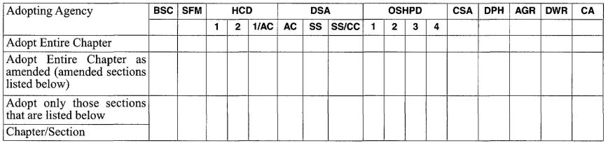
1501.0 General Requirements.
1501.1 Applicability. Piping penetrations of required fire-resistance-rated walls, partitions, floors, floor⁄ceiling assemblies, roof⁄ceiling assemblies, or shaft enclosures shall be protected in accordance with the requirements of the Building Code, and this chapter.
1502.0 Plans and Specifications.
1502.1 Plans and specifications shall indicate with sufficient detail how penetrations of fire-resistance-rated assemblies shall be firestopped prior to obtaining design approval.
1503.0 Installation.
1503.1 Firestop materials shall be installed in accordance with this chapter, the Building Code, and the manufacturer’s instructions.
1504.0 Definitions.
1504.1 Penetration Firestop System. A specific assemblage of field-assembled materials, or a factory-made device, which has been tested to a standard test method and, when installed properly on penetrating piping materials, is capable of maintaining the fire-resistance rating of assemblies penetrated.
1504.2 F Rating. The time period that the penetration firestop system limits the spread of fire through the penetration, when tested in accordance with ASTM E 814, Standard for Fire Tests of Through-Penetration Fire Stops, or UL 1479, Standard for Fire Tests of Through-Penetration Firestops.
1504.3 T Rating. The time period that the penetration firestop system, including the penetrating item, limits the maximum temperature rise of 325°F (163°C) above its initial temperature through the penetration on the nonfire side, when tested in accordance with ASTM E 814, Standard for Fire Tests of Through-Penetration Fire Stops, or UL 1479, Standard for Fire Tests of Through-Penetration Firestops.
1505.0 Combustible Piping Installations.
1505.1 Combustible piping installations shall be protected in accordance with the appropriate fire resistance rating requirements in the Building Code that list the acceptable area, height, and type of construction for use in specific occupancies to assure compliance and integrity of the fire resistance rating prescribed.
1505.2 When penetrating a fire-resistance-rated wall, partition, floor, floor-ceiling assembly, roof-ceiling assembly, or shaft enclosure, the fire resistance rating of the assembly shall be restored to its original rating.
1505.3 Penetrations shall be protected by an approved penetration firestop system installed as tested in accordance with ASTM E 119, Standard for Fire Tests of Building Construction and Materials, ASTM E 814, Standard for Fire Tests of Through-Penetration Fire Stops, UL 263, Standard for Fire Tests of Building Construction and Materials, or UL 1479, Standard for Fire Tests of Through-Penetration Firestops, with a positive pressure differential of not less than one-one-hundredth (0.01) of an inch of water. Systems shall have an F rating of not less than one (1) hour but not less than the required fire resistance rating of the assembly being penetrated. Systems protecting floor penetrations shall have a T rating of not less than one (1) hour but not less than the required fire resistance rating of the floor being penetrated. Floor penetrations contained within the cavity of a wall at the location of the floor penetration do not require a T rating. No T rating shall be required for floor penetrations by piping that is not in direct contact with combustible material.
1505.4 When piping penetrates a rated assembly, combustible piping shall not connect to non-combustible piping unless it can be demonstrated that the transition complies with the requirements of Section 1505.3.
1505.5 Insulation and Coverings. Insulation and coverings on or in the penetrating item shall not be permitted unless the specific insulating or covering material has been tested as part of the penetrating firestop system.
1505.6 Sleeves. Where sleeves are used, the sleeves should be securely fastened to the fire-resistance-rated assembly. The (inside) annular space between the sleeve and the penetrating item and the (outside) annular space between the sleeve and the fire-resistance-rated assembly shall be firestopped in accordance with the requirements for a sleeve penetrating item.
1506.0 Non-Combustible Piping Installations.
1506.1 Non-Combustible piping installations shall be protected in accordance with the appropriate fire resistance rating requirements in the Building Code that list the acceptable area, height, and type of construction for use in specific occupancies to ensure compliance and integrity of the fire-resistance rating prescribed.
1506.2 When penetrating a fire-resistance-rated wall, partition, floor, floor-ceiling assembly, roof-ceiling assembly, or shaft enclosure, the fire-resistance rating of the assembly shall be restored to its original rating.
Exceptions:
1506.3 Penetration shall be protected by an approved penetration firestop system installed as tested in accordance with ASTM E 119, Standard for Fire Tests of Through-Penetration Fire Stops, UL 263, Standard for Fire Tests of Building Construction and Materials ASTM E 814, Standard for Fire Tests of Through-Penetration Firestops, with a positive pressure differential of not less than one-one-hundredth (0.01) of an inch of water. Systems shall have an F rating of not less than one (1) hour but not less than the required fire-resistance rating of the assembly being penetrated. Systems protecting floor penetrations shall have a T rating of not less than one (1) hour but not less than the required fire resistance rating of the floor being penetrated. Floor penetrations contained within the cavity of a wall at the location of the floor penetration do not require a T rating. No T rating shall be required for floor penetrations by piping that is not in direct contact with combustible material.
1506.4 When piping penetrates a rated assembly, combustible piping shall not connect to non-combustible piping unless it can be demonstrated that the transition complies with the requirements of Section 1506.3.
1506.5 Unshielded couplings shall not be used to connect noncombustible piping unless it can be demonstrated that the fire-resistive integrity of the penetration is maintained.
1506.6 Sleeves. Where sleeves are used, the sleeves should be securely fastened to the fire-resistance-rated assembly. The (inside) annular space between the sleeve and the penetrating item and the (outside) annular space between the sleeve and the fire-resistance-rated assembly shall be firestopped in accordance with the requirements for a sleeve-penetrating item.
1506.7 Insulation and Coverings. Insulation and coverings on or in the penetrating item shall not be permitted unless the specific insulating or covering material has been tested as part of the penetrating firestop system.
1507.0 Required Inspection.
1507.1 General. Prior to being concealed, piping penetrations shall be inspected by the Authority Having Jurisdiction to verify compliance with the fire-resistance rating prescribed in the Building Code.
1507.2 The Authority Having Jurisdiction shall conduct a thorough examination of sufficient representative installations, including destructive inspection, to provide verification of satisfactory compliance with this chapter, the appropriate manufacturers installation standards applied by the installer, construction documents, specifications, and applicable manufacturers product information.
1507.3 The Authority Having Jurisdiction shall determine the type, size, and quantity of penetrations to be inspected.
1507.4 The Authority Having Jurisdiction shall compare the field installations with the documentation supplied by the installer to determine the following:
| Adopting Agency | BSC | SFM | HCD | DSA | OSHPD | CSA | DPH | AGR | DWR | CA | |||||||
|---|---|---|---|---|---|---|---|---|---|---|---|---|---|---|---|---|---|
| 1 | 2 | 1/AC | AC | SS | SS/CC | 1 | 2 | 3 | 4 | ||||||||
| Adopt Entire Chapter | |||||||||||||||||
| Adopt Entire Chapter as amended (amended sections listed below) | |||||||||||||||||
| Adopt only those sections that are listed below | X | X | |||||||||||||||
| Chapter/Section | |||||||||||||||||
| Part I | X | ||||||||||||||||
| Part II | X | ||||||||||||||||
Intent
This part is applicable to occupancies under the authority of the Department of Housing and Community Development as specified in Section 1.8.2.1.1 and is intended to:
1601A.0 Graywater Systems-General.
Note: It is not the intent of this section to require that all graywater must be handled by an irrigation field or disposal field. It is acceptable for excess graywater to be diverted to the building sewer through the overflow required pursuant to Section 1609A.0(E)
Exception: When there exist a lawfully recorded perpetual and exclusive convenient to an easement appurtenant and right-of-way between adjoining land-owners of two or more contiguous lots to discharge graywater from one lot to an adjoining lot.
Exception: A construction permit shall not be required for a clothes washer system which does not require cutting of the existing plumbing piping provided it is in compliance with Section 1603A.1.1
1602A.0 Definitions.
Clothes Washer System. A graywater system utilizing only a single domestic clothes washing machine in a one- or two- family dwelling.
Complex System. Graywater systems that discharge over 250 gallons (947 L) per day.
Disposal Field. An intended destination for graywater including but not limited to a mulch basin or receiving land scape feature, graywater leach field, or other approved method of disposal.
Graywater. Pursuant to Health and Safety Code Section 17922.12, ″graywater″ means untreated wastewater that has not been contaminated by any toilet discharge, has not been affected by infectious, contaminated, or unhealthy bodily wastes, and does not present a threat from contamination by unhealthful processing, manufacturing, or operating wastes. ″Graywater″ includes but is not limited to waste water from
bathtubs, showers, bathroom washbasins, clothes washing machines, and laundry tubs, but does not include waste water from kitchen sinks or dishwashers.
Graywater System. A system designed to collect graywater and transport it out of the structure for distribution in an Irrigation or Disposal Field. A graywater system may include tanks, valves, filters, pumps or other appurtenances along with piping and receiving landscape.
Irrigation Field. An intended destination for graywater in the receiving landscape including but not limited to a drip irrigation system, mulch basin, or other approved method of dispersal for irrigation purposes.
Mulch. Organic waste material including but not limited to leaves, prunings, straw, pulled weeds, and wood chips. Mulch shall be permeable enough to allow rapid infiltration of graywater.
Mulch Basin. A type of irrigation or disposal field filled with mulch or other approved permeable material of sufficient depth, length, and width to prevent ponding or runoff. A mulch basin may include a basin around a tree, a through along a row of plants, or other shapes necessary for irrigation or disposal.
Receiving Landscape. Includes features such as soil, basins, swales, mulch, and plants.
Simple System. A graywater system serving a one- or twofamily dwelling with a discharge of 250 gallons (947 L) per day or less. Simple systems exceed a clothes washer system.
Treated Graywater. Non-potable water collected and treated on-site suitable for direct beneficial use.
1603A.0 Permit.
A written construction permit shall be obtained from the Enforcing Agency prior to the erection, construction, reconstruction, installation, relocation, or alteration of any graywater system that requires a permit.
Exception: A construction permit shall not be required for a clothes washer system which does not require cutting of the existing plumbing piping provided it is in compliance with Section 1603A.1.1.
1603A.1 System Requirements.
1603A.1.1 Clothes Washer System. A clothes washer system in compliance with all of the following is exempt from the construction permit specified in Section 1.8.4.1 and may be installed or altered without a construction permit:
Note: A city, county, or city and county or other local government may, after a public hearing and enactment of an ordinance or resolution, further restrict or prohibit the use of graywater systems. For additional information, see Health and Safety Code Section 18941.7.
Note: The pump in a clothes washer shall not be considered part of the graywater system.
1603A.1.2 Simple System. Simple systems exceed a clothes washer system and shall comply with the following:
1603A.1.3 Complex System. Any graywater system that is not a clothes washer system or simple system shall comply with the following:
| TYPE OF SYSTEM | PERMIT REQUIREMENTS |
|---|---|
| Clothes washer System | No construction permit required if conditions in Section 1603A.1.1 are met. |
| Simple System | Permit and plans required unless exempted by Enforcing Agency. |
| Complex System | Permit and plans required unless exempted by Enforcing Agency. |
| Treated Graywater | Permit and plans required unless exempted by Enforcing Agency. |
1604.4.0 Drawings and Specifications.
Graywater systems for which a construction permit is required may be subject to submitted of plans and details of the proposed graywater system necessary to ensure compliance with the requirements of this chapter. Identification of the ground water level and soil absorption qualities at the site shall be included in the plans or provided to the Enforcing Agency.
Exception: The Enforcing Agency may waive the requirement for identification of groundwater level and/or soil absorption qualities based on knowledge of local conditions.
1604A.1 Groundwater Depth. Verification of ground water levels which exceed three (3) vertical feet (915 mm) from the deepest irrigation or disposal point of the proposed graywater system shall not be required.
Note: The absence of groundwater in a test hole three (3) vertical feet (915 mm) below the deepest irrigation or disposal point shall be sufficient to satisfy this section unless seasonal high groundwater levels have been documented to rise to within this area.
1605A.0 Inspection and Testing.
1606A.0 Procedure for Estimating Graywater Discharge.
Exception: Treated graywater systems when approved by the Enforcing Agency.
1607A.0 Required Area of Irrigation or Disposal Fields.
Irrigation or disposal fields may have one or more valved zones. Each zone must be of adequate size to receive the graywater anticipated in that zone. No irrigation or disposal field shall extend within three (3) vertical feet (915 mm) of the highest known seasonal groundwater, or a to a depth where graywater contaminates the groundwater, ocean water or surface water. The applicant shall supply evidence of ground water depth to the satisfaction of the Enforcing Agency.
Note: The absence of groundwater in a test hole three (3) vertical feet (915 mm) below the deepest irrigation or disposal point shall be sufficient to satisfy this section unless seasonal high groundwater levels have been documented to rise to within this area.
1608A.0 Determination of Maximum Absorption Capacity.
Exception: Irrigation fields in compliance with Section 1611A.2, which only utilize drip type emitters.
Exception: The Enforcing Agency may waive the requirement for percolation tests based on knowledge of local conditions or accept other testing methods.
1609A.0 Tank Construction.
610A .0 Graywater Systems.
Graywater systems shall comply with Section 1610A.1 through 1610A.3.
1610A .1 Pipe Materials. Graywater pipe, valves, and fittings shall conform to the requirements of Sections 604.0, 605.0, and 606.0.
1610A.2 Identification. Graywater distribution piping upstream of any connection to an irrigation or disposal field or a distribution valve shall be identified with the words ″CAUTION: NON-POTABLE WATER, DO NOT DRINK.″ Marking shall be at intervals not be exceed five (5) feet (1,524 mm).
1610A.3 Valves. All valves shall be accessible. A backwater valve installed pursuant to this code shall be provided on all tank drain connections to the sanitary drain or sewer piping.
1611A.0 Irrigation, Disposal Field, and Mulch Basin Construction.
Irrigation fields, disposal fields, and mulch basins used in graywater system shall comply with this section. Graywater systems may contain either an irrigation field or a disposal field or a combination of both. This section is not intended to prevent the use of other methods of graywater irrigation or disposal approved by the Enforcing Agency.
1611A.1 Mulch Basin. A mulch basin may be used as an irrigation or disposal field. Mulch basins shall be sized in accordance with Table 16A-2 and of sufficient depth, length, and width to prevent ponding or runoff during the graywater surge of a clothes washer, bathtub, or shower, Mulch must be replenished as required due to decomposition of organic matter. Mulch basins will require periodic maintenance, reshaping, or removal of dirt to maintain surge capacity and to accommodate plant growth and prevent ponding or runoff.
1611A.2 Irrigation Field. The provisions of this section are not intended to prevent the use of any appropriate material, appliance, installation, device, design, or method of construction. If an alternate design is not available, the following provisions may be used as guidance in the design of a graywater irrigation field:
1611A.3 Disposal Field. The provisions of this section are not intended to prevent the use of any appropriate material, appliance, installation, device, design, or method of construction. If an alternate design is not available the following provisions may be used as guidance in the design of a graywater disposal field:
Exception. Manufactured leaching chambers shall be installed in compliance with the manufacturer’s installation instructions.
| MINIMUM | MAXIMUM | |
|---|---|---|
| 1 Manufactured leaching chambers shall be installed in compliance with the manufacturer’s installation instructions. | ||
| Number of drain lines per valved zone1 | 1 | — |
| Length of each perforated line1 | — | 100 ft. (30,840 mm) |
| Bottom width of trench1 | 12 in. (305 mm) | 24 in. (610 mm) |
| Spacing of lines, center to center1 | 4 ft. (1219 mm) | — |
| Depth of earth cover of lines | 2 in. (51 mm) | — |
| Depth of filter material cover of lines | 2 in. (51 mm) | — |
| Depth of filter material beneath lines1 | 3 in. (76 mm) | — |
| Grade of perforated lines | level | 3 in./100 ft. (2 mm/m) |
1612A.0 Special Provisions.
1612A.1 Indoor Use of Treated Graywater. Graywater shall not be allowed for indoor use, such as flushing toilets and urinals, unless treated by an on-site water treatment system approved by the Enforcing Agency. For the purposes of this section, graywater treated by an on-site water treatment system shall be considered “Treated Graywater”. Treated graywater and treated graywater systems shall comply with the
305provisions of this code except as otherwise provided in this chapter and all of the following:
| MINIMUM HORIZONTAL DISTANCE REQUIRED FROM | TANK | IRRIGATION FIELD | DISPOSAL FIELD |
|---|---|---|---|
| feet/mm | feet/mm | feet/mm | |
| 1 Building structure does not include porches and steps, whether covered or uncovered, breezeways, roofed porte cocheres, roofed patios, carports, covered walks, covered driveways, and similar structures or appurtenances. | |||
| 2 Underground tanks shall not be located within a 45 degree angle from the bottom of the foundation, or they shall be designed to address the surcharge imposed by the structure. The distance may be reduced to six (6) inches (153 mm) for aboveground tanks when first approved by the Enforcing Agency. | |||
| 3 Where special hazards are involved, the distance required shall be increased as directed by the Enforcing Agency. | |||
| 4 These minimum clear horizontal distances shall also apply between the irrigation or disposal field and the ocean mean higher hightide line. | |||
| 5 The minimum horizontal distance may be reduced to 50 feet (15,240 mm) for irrigation fields utilizing graywater which has been filtered prior to entering the distribution piping. | |||
| 6 Plus two (2) feet (610 mm) for each additional foot of depth in excess of one (1) foot (305 mm) below the bottom of the drain line. | |||
| 7 For parallel construction or crossings, approval by the Enforcing Agency shall be required. | |||
| Building structures1 | 5(1,524 mm)2 | 2(610 mm) | 5(1,524 mm) |
| Property line adjoining private property | 5 (1,524 mm) | 1.5 feet (458 mm) | 5(1,524 mm) |
| Water supply wells3 | 50 (15,240 mm) | 100 (30,480 mm) | 100(30,480 mm) |
| Streams and lakes3 | 50 (15,240 mm) | 100 (30,480 mm)4,5 | 100 (30,480 mm)4 |
| Sewage pits or cesspools | 5 (1,524 mm) | 5 (1,524 mm) | 5 (1,524 mm) |
| Sewage disposal field | 5 (1,524 mm) | 4 (1,219 mm)6 | 4 (1,219 mm)6 |
| Septic tank | 0(0) | 5(1,524 mm) | 5(1,524 mm) |
| On-site domestic water service line | 5 (1,524 mm) | 0(0 mm) | 0(0mm) |
| Pressurized public water main | 10 (3,048 mm) | 10 (3,048 mm)7 | 10(3,048 mm)7 |
| TYPE OF SOIL | SQUARE FEET | GALLONS | SQUARE METERS | LITERS |
|---|---|---|---|---|
| Minimum square feet of Irrigation/leaching area per 100 gallons of estimated graywater discharge per day | Maximum absorption capacity in gallons per square foot of Irrigation/leaching area for a 24-hour period | Minimum square meters of Irrigation/leaching area per liter of estimated graywater discharge per day | Maximum absorption capacity in liters per square meter of Irrigation/leaching area for a 24-hour period | |
| Coarse sand or gravel | 20 | 5.0 | 0.005 | 203.7 |
| Fine sand | 25 | 4.0 | 0.006 | 162.9 |
| Sandy loam | 40 | 2.5 | 0.010 | 101.8 |
| Sandy clay | 60 | 1.7 | 0.015 | 69.2 |
| Clay with considerable sand or gravel | 90 | 1.1 | 0.022 | 44.8 |
| Clay with small amounts ofTABLE 16A-3 sand or gravel | 120 | 0.8 | 0.030 | 32.6 |
| TYPE OF SOIL | MAXIMUM EMITTER DISCHARGE (gal/day) | MINIMUM NUMBER OF EMITTERS PER GPD OF GRAYWATER PRODUCTION |
|---|---|---|
| Use the daily graywater flow calculated in Section 1606A.0 to determine the number of emitters per line. | ||
| 1. Sand | 1.8 | 0.6 |
| 2. Sandy loam | 1.4 | 0.7 |
| 3. Loam | 1.2 | 0.9 |
| 4. Clay loam | 0.9 | 1.1 |
| 5. Silty clay | 0.6 | 1.6 |
| 6. Clay | 0.5 | 2.0 |
1613A.0 Recycled Water System - General
1614A.0 Definitions.
Recycled Water. Non-potable water that meets California Department of Public Health statewide uniform criteria for disinfected tertiary recycled water. Recycled water is also known as reclaimed water.
1615A.0 Permit.
It shall be unlawful for any person to construct, install, alter, or cause to be constructed, installed, or altered any recycled water system within a building or on a premises without first obtaining a permit to do such work from the Authority Having Jurisdiction. Section 13553 of the Water Code specifies structures where indoor use of recycled water is allowed. These structures include commercial, retail and office buildings, theaters, auditoriums, condominium projects, schools, hotels, apartments, barracks, dormitories, jails, prisons, reformatories, and other structures as determined by the State Department of Public Health.
1616A.0 Drawings and Specifications.
1617A.0 Pipe Material/Pipe Identification.
Recycled water pipe shall comply with Sections 1617A.1 and 1617A.2.
1617A.1 Pipe Materials. Recycled water pipe, valves, and fittings shall conform to the requirements of Sections 604.0, 605.0, and 606.0.
1617A.2 Color and Information. Recycled water systems shall have a purple background with black uppercase lettering with the words “CAUTION: RECYCLED WATER, DO NOT DRINK.”
All recycled water pipe shall be permanently marked to identify that it contains recycled water. This may be accomplished by labeling piping using purple-colored (Pantone color512) adhesive Mylar PVC tape along the entire length of the pipe or using non-metallic pipe manufactured with purple integral to the material. For either material, the identification system shall be installed so the wording above is clearly visible.
1618A.0 Installation.
1619A.0 Signs.
TO CONSERVE WATER,
THIS BUILDING USES RECYCLED
WATER TO FLUSH TOILETS AND URINALS.
CAUTION
RECYCLED WATER,
DO NOT DRINK.
DO NOT CONNECT TO DRINKING WATER
SYSTEM.
This sign shall be posted in a location that is visible to anyone working on or near recycled water equipment.NOTICE,
CONTACT BUILDING MANAGEMENT
BEFORE
PERFORMING ANY WORK ON
THIS WATER SYSTEM.
RECYCLED WATER– DO NOT DRINK
1620A.0 Inspection and Testing.
1621A.0 Sizing.
Recycled water piping shall be sized as outlined in this code for sizing potable water piping.
The appendices are intended to supplement the provisions of the installation requirements of this code. The definitions in Chapter 2 are also applicable to the appendices.
| Page | |
|---|---|
| APPENDIX A Recommended Rules for Sizing the Water Supply System | 315 |
| APPENDIX B Explanatory Notes on Combination Waste and Vent Systems | 333 |
| APPENDIX D Sizing Storm Water Drainage Systems | 337 |
| APPENDIX G Graywater Systems | 347 |
| APPENDIX IInstallation Standards | 359 |
| APPENDIX K Private Sewage Disposal Systems | 457 |
| APPENDIX L Alternate Plumbing Systems | 469 |
| Adopting Agency | BSC | SFM | HCD | DSA | OSHPD | CSA | DPH | AGR | DWR | CA | |||||||
|---|---|---|---|---|---|---|---|---|---|---|---|---|---|---|---|---|---|
| 1 | 2 | 1/AC | AC | SS | SS/CC | 1 | 2 | 3 | 4 | ||||||||
| Adopt Entire Chapter | X | X | X | X | X | X | X | X | X | ||||||||
| Adopt Entire Chapter as amended (amended sections listed below) | |||||||||||||||||
| Adopt only those sections that are listed below | |||||||||||||||||
| Chapter/Section | |||||||||||||||||
Because of the variable conditions encountered, it is impractical to lay down definite detailed rules of procedure for determining the sizes of water supply pipes in an appendix, which must necessarily be limited in length. For a more adequate understanding of the problems involved, refer to Water-Distributing Systems for Buildings, Report BMS 79 of the National Bureau of Standards; and Plumbing Manual, Report BMS 66, also published by the National Bureau of Standards.
The following is a suggested order of procedure for sizing the water supply system.
A 1.0 Preliminary Information.
A 1.1 Obtain the necessary information regarding the minimum daily service pressure in the area where the building is to be located.
A 1.2 If the building supply is to be metered, obtain information regarding friction loss relative to the rate of flow for meters in the range of sizes likely to be used. Friction-loss data can be obtained from most manufacturers of water meters. Friction losses for disk-type meters shall be permitted to be obtained from Chart A-1.
A 1.3 Obtain all available local information regarding the use of different kinds of pipe with respect both to durability and to decrease in capacity with length of service in the particular water supply.
A 2.0 Demand Load.
A 2.1 Estimate the supply demand for the building main, the principal branches and risers of the system by totaling the fixture units on each, Table A-2, and then by reading the corresponding ordinate from Chart A-2 or A-3, whichever is applicable.
A 2.2 Estimate continuous supply demands in gallons per minute (liters per second) for lawn sprinklers, air conditioners, etc., and add the sum to the total demand for fixtures. The result is the estimated supply demand of the building supply.
A 3.0 Permissible Friction Loss.
A 3.1 Decide what is the desirable minimum residual pressure that shall be maintained at the highest fixture in the supply system. If the highest group of fixtures contains flushometer valves, the residual pressure for the group shall not be less than fifteen (15) psi (103 kPa). For flush tank supplies, the available residual pressure shall not be less than eight (8) psi (55 kPa).
A3.2 Determine the elevation of the highest fixture or group of fixtures above the water (street) main. Multiply this difference in elevation by forty-three hundredths (0.43). The result is the loss in static pressure in psi (pounds per square inch) (kPa).
A3.3 Subtract the sum of loss in static pressure and the residual pressure to be maintained at the highest fixture from the average minimum daily service pressure. The result will be the pressure available for friction loss in the supply pipes, if no water meter is used. If a meter is to be installed, the friction loss in the meter for the estimated maximum demand should also be subtracted from the service pressure to determine the pressure loss available for friction loss in the supply pipes.
A 3.4 Determine the developed length of pipe from the water (street) main to the highest fixture. If close estimate are desired, compute with the aid of Table A-3, the equivalent length of pipe for all fittings in the line from the water (street) main to the highest fixture and add the sum to the developed length. The pressure available for friction loss in pounds per square inch (kPa), divided by the developed lengths of pipe from the water (street) main to the highest fixture, times one hundred (100), will be the average permissible friction loss per one-hundred (100) feet (30,480 mm) length of pipe.
A 4.0 Size of Building Supply.
A 4.1 Knowing the permissible friction loss per one-hundred (100) feet (30,480 mm) of pipe and the total demand, the diameter of the building supply pipe shall be permitted to be obtained from Charts A-4, A-5, A-6, or A-7, whichever is applicable. The diameter of pipe on or next above the coordinate point corresponding to the estimated total demand and the permissible friction loss will be the size needed up to the first branch from the building supply pipe.
A 4.2 If copper tubing or brass pipe is to be used for the supply piping and if the character of the water is such that only slight changes in the hydraulic characteristics may be expected, Chart A-4 shall be permitted to be used.
A 4.3 Chart A-5 should be used for ferrous pipe with only the most favorable water supply in regards to corrosion and caking. If the water is hard or corrosive, Chapter A-6 or A-7 will be applicable. For extremely hard water, it will be advisable to make additional allowances for the reduction of capacity of hot-water lines in service.
A 5.0 Size of Principal Branches and Risers.
A 5.1 The required size of branches and risers shall be permitted to be obtained in the same manner as the building supply, by obtaining the demand load on each branch or riser and using the permissible friction loss computed in Section A 3.0.
A 5.2 Fixture branches to the building supply, if they are sized for the same permissible friction loss per one-hundred (100) feet (30,480 mm) of pipe as the branches and risers to the highest level in the building, may lead to in adequate water supply to the upper floor of a building. This may be controlled by (1) selecting the sizes of pipe
for the different branches so that the total friction loss in each lower branch is approximately equal to the total loss in the riser, including both friction loss and loss in static pressure; (2) throttling each such branch by means of a valve until the preceding balance is obtained; (3) increasing the size of the building supply and risers above the minimum required to meet the maximum permissible friction loss.
A 5.3 The size of branches and mains serving flushometer tanks shall be consistent with sizing procedures for flush tank water closets.
A 6.0 General.
A 6.1 Velocities shall not exceed ten (10) feet/second (3.0m/sec.) or the maximum values given in the appropriate Installation Standard, except as otherwise approved by the Authority Having Jurisdiction.
A 6.2 If a pressure-reducing valve is used in the building supply, the developed length of supply piping and the permissible friction loss should be computed from the building side of the valve.
A 6.3 The allowances in Table A-3 for fittings are based on non-recessed threaded fittings. For recessed threaded fittings and streamlined soldered fittings, one-half (½) of the allowances given in the table will be ample.
A 7.0 Example.
A 7.1 Assume an office building of four (4) stories and basement; pressure on the building side of the pressure-reducing valve of fifty-five (55) psi (379 kPa) (after an allowance for reduced pressure falloff at peak demand); an elevation of highest fixture above the pressure-reducing valve of forty-five (45) feet (13,716 mm); a developed length of pipe from the pressure-reducing valve to the most distant fixture of two-hundred (200) feet (60,960 mm); and fixtures to be installed with flush valves for water closets and stall urinals as follows:
If the pipe material and water supply are such that Chart A-5 applies, the required diameter of the building supply is three and one-half (3½) inches (88.9 mm) and the required diameter of the branch to the hot-water heater is one and one-half (1½) inches (40 mm).
The sizes of the various branches and risers shall be permitted to be determined in the same manner as the size of the building supply or the branch to the hot-water system, by estimating the demand for the riser or branch from Chart A-2 or A-3 and applying the total demand estimate from the branch, riser, or section thereof to the appropriate flowchart.
| FIXTURE UNITS AND ESTIMATED DEMANDS | |||||||
|---|---|---|---|---|---|---|---|
| BUILDING SUPPLY DEMAND | BRANCH TO HOT WATER SYSTEM | ||||||
| KIND OF FIXTURES | NO. OF FIXTURES | FIXTURE UNIT DEMAND | TOTAL UNITS | BUILDING SUPPLY DEMAND IN GPM (L per sec) | NO. OF FIXTURES | FIXTURE UNIT DEMAND CALCULATION | DEMAND IN GALLONS PER MINUTE (L per sec) |
| Water Closets | 130 | 8.0 | 1,040 | – | – | – | – |
| Urinals | 30 | 4.0 | 120 | – | – | – | – |
| Shower heads | 12 | 2.0 | 24 | – | 12 | 12x2x¾=18 | – |
| Lavatories | 100 | 1.0 | 100 | – | 100 | 100x1x¾=75 | – |
| Service Sinks | 27 | 3.0 | 81 | – | 27 | 27x3x¾=61 | – |
| Total | 1,365 | 252 gpm (15.8 L/s) | 154 | 55 gpm (3.4 L/s) | |||
Allowing for 15 psi (103.4 kPa) at the highest fixture under the maximum demand of 252 gallons per minute (15.8 L/sec.), the pressure available for friction loss is found by the following:
55 – [15 + (45 x 0.43)] = 20.65 psi
Metric: 379 – [103.4 + (13.7 x 9.8)] = 142.3 kPa
The allowable friction loss per 100 feet (30.4 m) of pipe is therefore:
100 x 20.65 ÷ 200 = 10.32 psi
Metric: 30.4 x 142.3 ÷ 60.8 = 71.1 kPa
| APPLIANCES, APPURTENANCE, OR FIXTURES2 | MINIMUM FIXTURE BRANCH PIPE SIZE1,4 | PRIVATE | PUBLIC | ASSEMBLY6 |
|---|---|---|---|---|
| Notes: | ||||
| 1. Size of the cold branch pipe, or both the hot and cold branch pipes. | ||||
| 2. Appliances, Appurtenances, or Fixtures not included in this Table may be sized by reference to fixtures having a similar flow rate and frequency of use. | ||||
| 3. The listed fixture unit values represent their total load on the cold water service. The separate cold water and hot water fixture unit value for fixtures having both cold and hot water connections may each be taken as three-quarters (¾) of the listed total value of the fixture. | ||||
| 4. The listed minimum supply branch pipe sizes for individual fixtures are the nominal (I.D.) pipe size. | ||||
| 5. For fixtures or supply connections likely to impose continuous flow demands, determine the required flow in gallons per minute (GPM) and add it separately to the demand (in GPM) for the distribution system or portions thereof. | ||||
| 6. Assembly [Public Use (See Table 4-1)]. | ||||
| 7. Reduced fixture unit loading for additional hose bibbs is to be used only when sizing total building demand and for pipe sizing when more than one (1) hose bibb is supplied by a segment of water-distributing pipe. The fixture branch to each hose bibb shall be sized on the basis of two and one-half (2.5) fixture units. | ||||
| Bathtub or Combination Bath/Shower (fill) | ½ | 4.0 | 4.0 | – |
| ¾” Bathtub Fill Valve | ¾ | 10.0 | 10.0 | – |
| Bidet | ½ | 1.0 | – | – |
| Clothes Washer | ½ | 4.0 | 4.0 | – |
| Dental Unit, cuspidor | ½ | – | 1.0 | – |
| Dishwasher, domestic | ½ | 1.5 | 1.5 | – |
| Drinking Fountain or Water Cooler | ½ | 0.5 | 0.5 | 0.75 |
| Hose Bibb | ½ | 2.5 | 2.5 | – |
| Hose Bibb, each additional7 | ½ | 1.0 | 1.0 | – |
| Lavatory | ½ | 1.0 | 1.0 | 1.0 |
| Lawn Sprinkler, each head5 | 1.0 | 1.0 | – | |
| Mobile Home, each (minimum) | 12.0 | – | – | |
| Sinks | – | – | – | |
| Bar | ½ | 1.0 | 2.0 | – |
| Clinic Faucet | ½ | – | 3.0 | – |
| Clinic Flushometer Value with or without faucet | 1 | – | 8.0 | – |
| Kitchen, domestic | ½ | 1.5 | 1.5 | – |
| Laundry | ½ | 1.5 | 1.5 | – |
| Service or Mop Basin | ½ | 1.5 | 3.0 | – |
| Washup, each set of faucets | ½ | – | 2.0 | – |
| Shower per head | ½ | 2.0 | 2.0 | – |
| Urinal, 1.0 GPF Flushometer Valve | ¾ | 3.0 | 4.0 | 5.0 |
| Urinal, greater than 1.0 GPF Flushometer Valve. | ¾ | 4.0 | 5.0 | 6.0 |
| Urinal, flush tank | ½ | 2.0 | 2.0 | 3.0 |
| Wash Fountain, circular spray | ¾ | – | 4.0 | – |
| Water Closet, 1.6 GPF Gravity Tank | ½ | 2.5 | 2.5 | 3.5 |
| Water Closet, 1.6 GPF Flushometer Tank | ½ | 2.5 | 2.5 | 3.5 |
| Water Closet, 1.6 GPF Flushometer Valve | 1 | 5.0 | 5.0 | 8.0 |
| Water Closet, greater than 1.6 GPF Gravity Tank | ½ | 3.0 | 5.5 | 7.0 |
| Water Closet, greater than 1.6 GPF Flushometer Valve | 1 | 7.0 | 8.0 | 10.0 |
| DIAMETER OF FITTING (inches) | 90° STANDARD ELBOW(feet) | 45° STANDARD ELBOW (feet) | 90° STANDARD TEE(feet) | COUPLING OR STRAIGHT RUN OF TEE (feet) | GATE VALVE (feet) | GLOBE VALVE (feet) | ANGLE VALVE (feet) |
|---|---|---|---|---|---|---|---|
| *Allowances are based on nonrecessed threaded fittings. Use one-half (½) the allowances for recessed threaded fittings or streamlined solder fittings. | |||||||
| 3/8 | 1.0 | 0.6 | 1.5 | 0.3 | 0.2 | 8 | 4 |
| ½ | 2.0 | 1.2 | 3.0 | 0.6 | 0.4 | 15 | 8 |
| ¾ | 2.5 | 1.5 | 4.0 | 0.8 | 0.5 | 20 | 12 |
| 1 | 3.0 | 1.8 | 5.0 | 0.9 | 0.6 | 25 | 15 |
| 1¼ | 4.0 | 2.4 | 6.0 | 1.2 | 0.8 | 35 | 18 |
| 1½ | 5.0 | 3.0 | 7.0 | 1.5 | 1.0 | 45 | 22 |
| 2 | 7.0 | 4.0 | 10.0 | 2.0 | 1.3 | 55 | 28 |
| 2½ | 8.0 | 5.0 | 12.0 | 2.5 | 1.6 | 65 | 34 |
| 3 | 10.0 | 6.0 | 15.0 | 3.0 | 2.0 | 80 | 40 |
| 4 | 14.0 | 8.0 | 21.0 | 4.0 | 2.7 | 125 | 55 |
| 5 | 17.0 | 10.0 | 25.0 | 5.0 | 3.3 | 140 | 70 |
| 6 | 20.0 | 12.0 | 30.0 | 6.0 | 4.0 | 165 | 80 |
| DIAMETER OF FITTING (mm) | 90° STANDARD ELBOW (mm) | 45° STANDARD ELBOW (mm) | 90° STANDARD TEE (mm) | COUPLING OR STRAIGHT RUN OF TEE (mm) | GATE VALVE (mm) | GLOBE VALVE (mm) | ANGLE VALUE (mm) |
|---|---|---|---|---|---|---|---|
| 10 | 305 | 183 | 457 | 91 | 61 | 2,438 | 1,219 |
| 15 | 610 | 366 | 914 | 183 | 122 | 4,572 | 2,438 |
| 20 | 762 | 457 | 1,219 | 244 | 152 | 6,096 | 3,658 |
| 25 | 914 | 549 | 1,524 | 274 | 183 | 7,620 | 4,572 |
| 32 | 1,219 | 732 | 1,829 | 366 | 244 | 10,668 | 5,486 |
| 40 | 1,524 | 914 | 2,134 | 457 | 305 | 13,716 | 6,706 |
| 50 | 2,134 | 1,219 | 3,048 | 610 | 396 | 16,764 | 8,534 |
| 65 | 2,438 | 1,524 | 3,658 | 762 | 488 | 19,812 | 10,363 |
| 80 | 3,048 | 1,829 | 4,572 | 914 | 610 | 24,384 | 12,192 |
| 100 | 4,267 | 2,438 | 6,401 | 1,219 | 823 | 38,100 | 16,764 |
| 125 | 5,182 | 3,048 | 7,620 | 1,524 | 1,006 | 42,672 | 21,336 |
| 150 | 6,096 | 3,658 | 9,144 | 1,829 | 1,219 | 50,292 | 24,384 |
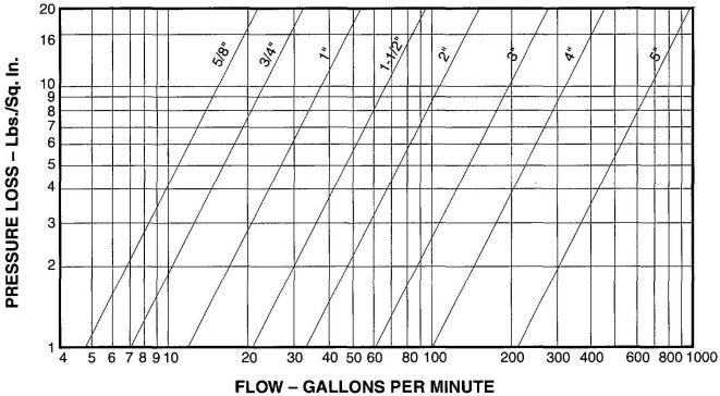
CHART A-1 FRICTION LOSSES FOR DISK-TYPE WATER METERS
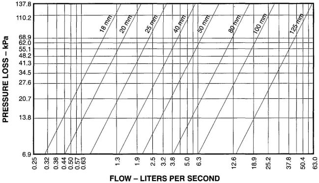
CHART A-1 (METRIC) FRICTION LOSSES FOR DISK-TYPE WATER METERS
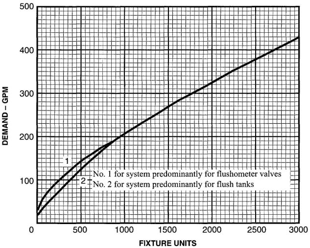
CHART A-2 ESTIMATE CURVES FOR DEMAND LOAD
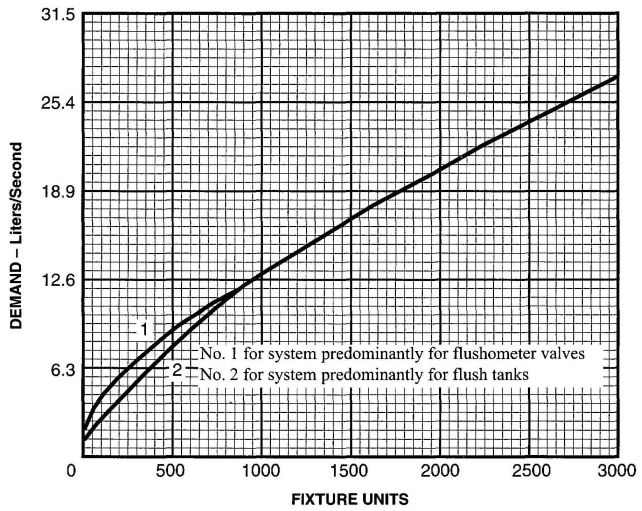
CHART A-2 (Metric) ESTIMATE CURVES FOR DEMAND LOAD
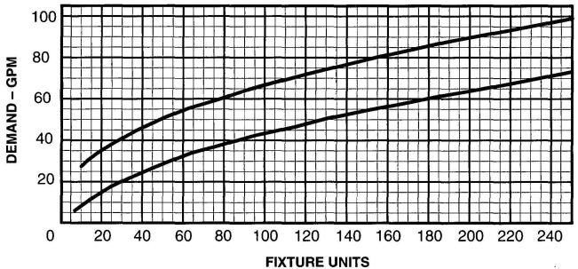
CHART A-3 ENLARGED SCALE DEMAND LOAD
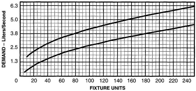
CHART A-3 (METRIC) ENLARGED SCALE DEMAND LOAD
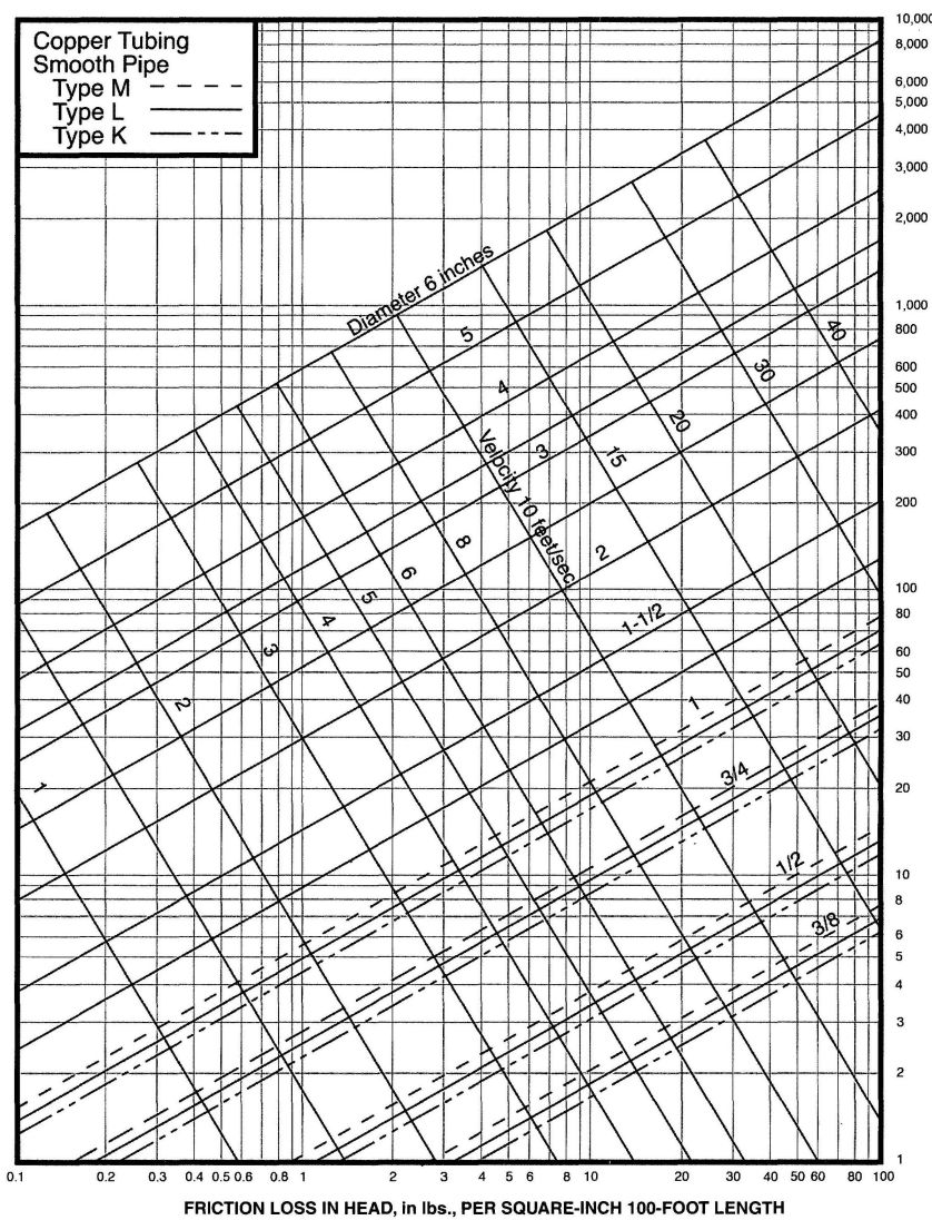
CHART A-4
CHART A-4 (METRIC)
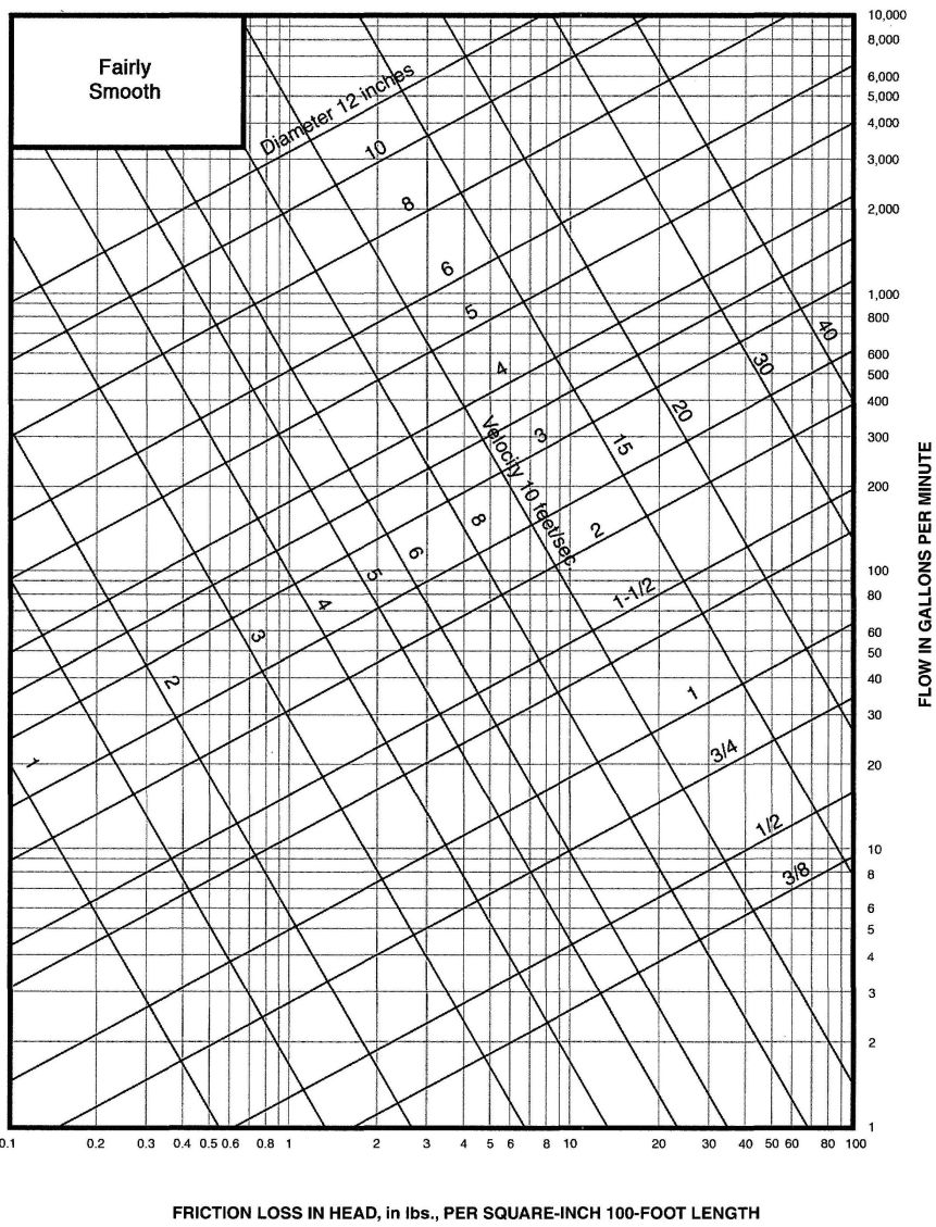
CHART A-5
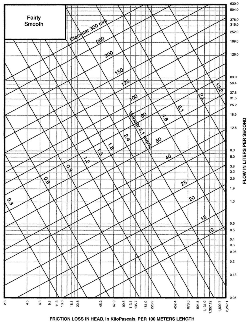
CHART A-5 (METRIC)
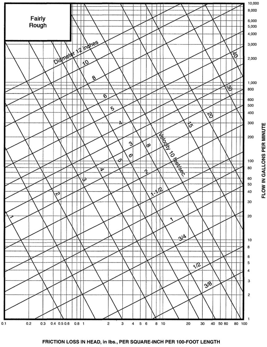
CHART A-6
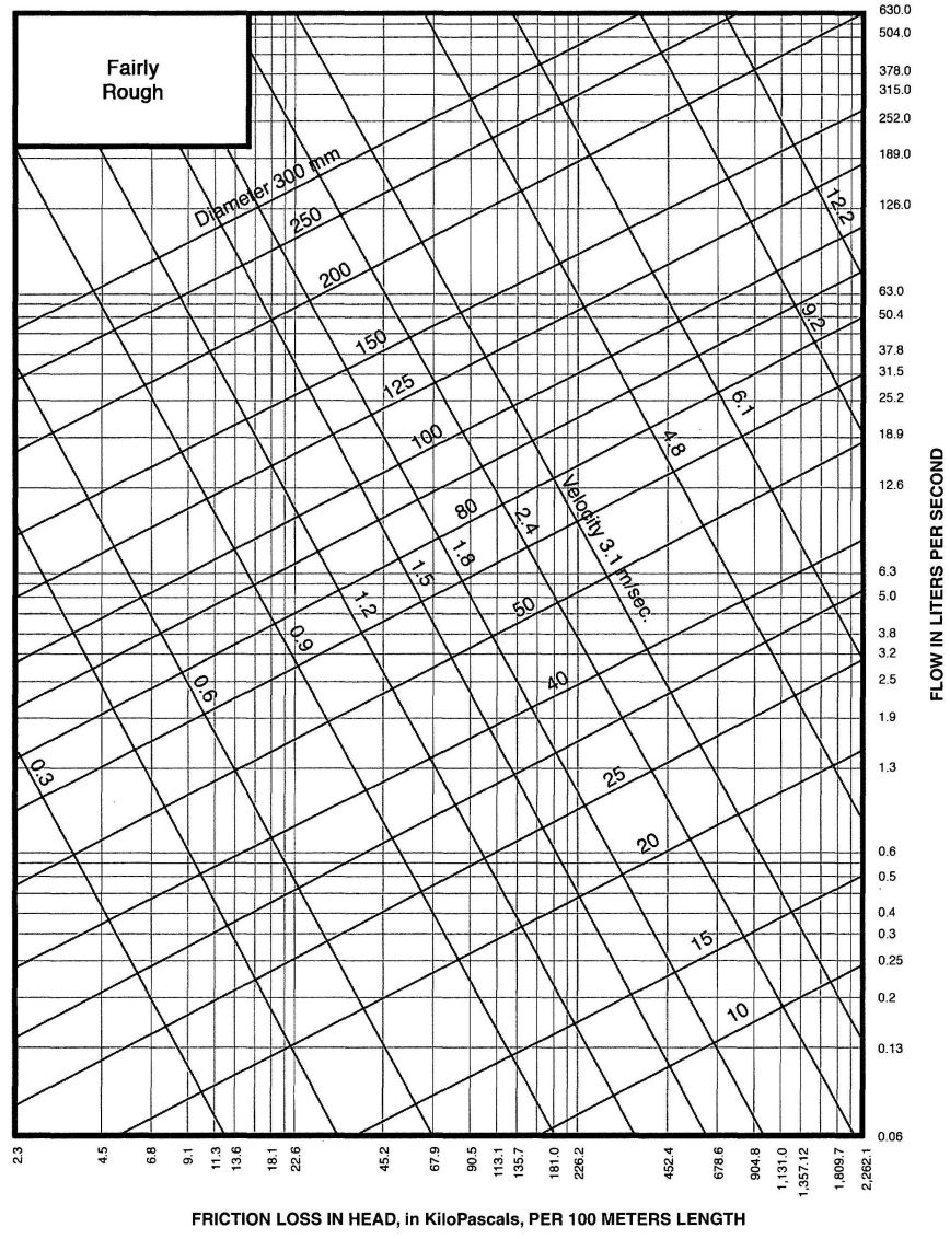
CHART A-6 (METRIC)
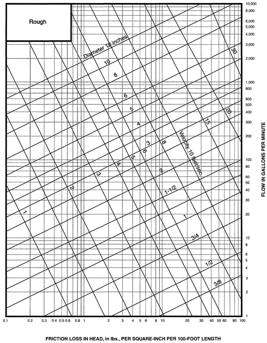
CHART A-7
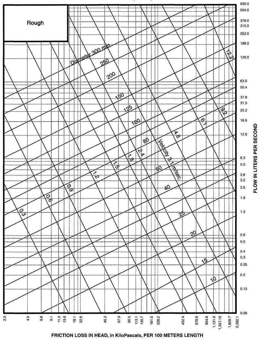
CHART A-7 (METRIC)
| Adopting Agency | BSC | SFM | HCD | DSA | OSHPD | CSA | DPH | AGR | DWR | CA | |||||||
|---|---|---|---|---|---|---|---|---|---|---|---|---|---|---|---|---|---|
| 1 | 2 | 1/AC | AC | SS | SS/CC | 1 | 2 | 3 | 4 | ||||||||
| Adopt Entire Chapter | X | X | X | X | X | X | X | ||||||||||
| Adopt Entire Chapter as amended (amended sections listed below) | |||||||||||||||||
| Adopt only those sections that are listed below | |||||||||||||||||
| Chapter/Section | |||||||||||||||||
(See Section 910.0 of the California Plumbing Code for specific limitations)
B 1.0 Combination waste and vent systems, as outlined in Section 910.0 of this code, cover the horizontal wet venting of a series of traps by means of a common waste and vent pipe. Pipe sizes at least two (2) pipe sizes larger than those required for a conventional system are designed to maintain a wetted perimeter or flow line low enough in the waste pipe to allow adequate air movement in the upper portion, thus balancing the system. Sinks, lavatories, and other fixtures that rough in above the floor, should not be permitted on a combination waste and vent system, which, at best, is merely an expedient designed to be used in locations where it would be structurally impractical to provide venting in the conventional manner.
Combination waste and vent systems are intended primarily for extensive floor or shower drain installations where separate venting is not practical, for floor sinks in markets, demonstration or work tables in school buildings, or for similar applications where the fixtures are not adjacent to walls or partitions. Due to its oversize characteristics, such a waste system is not self-scouring and, consequently, care should be the location of cleanouts. In view of its grease-producing potential, restaurant kitchen equipment should not be connected to a combination waste and vent system.
B 2.0 Caution must be exercised to exclude appurtenances delivering large quantities or surges of water (such as pumps, sand interceptors, etc.) from combination waste and vent systems in order that adequate venting will be maintained. Small fixtures with a waste-producing potential of less than seven and one-half (7½) gallons per minute (28.4 L/min.) shall be permitted to be safely assigned a loading value of one (1) unit. Long runs should be laid at the minimum permissible slope in order to keep tailpieces as short as possible. Tailpieces should not exceed two (2) feet (610 mm) in length, which may necessitate slopes up to forty-five (45) degrees (0.79 rad) (see definition of horizontal pipe) on some branches.
B 3.0 It is essential that the pneumatics of such a system be properly engineered, as the air pressure within the line must at all times balance that of outside atmosphere in order to prevent either trap seal loss or air locking between traps. Long mains shall be provided with additional relief vents located at intervals not exceeding one-hundred (100) feet (30,480 mm). Each such relief vent should equal at least one-half(½) of the inside cross-sectional area of the drain pipe served.
B 4.0 Trap sizes are required to be equivalent to the branches they serve (two (2) pipe sizes larger than normal), and tailpieces between fixtures or floor drains and such traps should be reduced to normal size.
B 5.0 Duplicate layout drawings of each such proposed piping system must be presented to the Authority Having Jurisdiction and approval obtained before any installation is made. Complicated layouts should be checked by qualified personnel.
B 5.1 Example of Sizing.
A floor drain normally requires a two (2) inch (50 mm) trap and waste. On a combination waste and vent system, both trap and waste must be increased two (2) pipe sizes (through ½"and 3") (65 mm and 80 mm), which would make the trap three (3) inches (80 mm). Pipe sizes recognized for this purpose are 2 in., 2½ in., 3 in., 3½ in., 4 in., 4½ in., 5 in., 6 in., etc. (50 mm, 65 mm, 80 mm, 90 mm, 100 mm, 115 mm, 125 mm, 150 mm, etc). The tail piece between the floor drain and its trap should be two (2) inches (50 mm) (or normal size) to ensure that the amount of wastewater entering the trap only partially fills the waste branch. A three (3) inch (80 mm) floor drain would thus require a four (4) inch (100 mm) trap, a four (4) inch (100 mm) floor drain, and five (5) inch (125 mm) trap, etc., for the reasons previously stated.
WHEN IN DOUBT, CHECK WITH YOUR LOCAL Authority Having Jurisdiction.
| Adopting Agency | BSC | SFM | HCD | DSA | OSHPD | CSA | DPH | AGR | DWR | CA | |||||||
|---|---|---|---|---|---|---|---|---|---|---|---|---|---|---|---|---|---|
| 1 | 2 | 1/AC | AC | SS | SS/CC | 1 | 2 | 3 | 4 | ||||||||
| Adopt Entire Chapter | X | X | X | X | X | X | X | X | X | ||||||||
| Adopt Entire Chapter as amended (amended sections listed below) | |||||||||||||||||
| Adopt only those sections that are listed below | |||||||||||||||||
| Chapter/Section | |||||||||||||||||
D 1.0 Roof Drainage.
The rainfall rates in Table D-1 should be used for design unless higher values are established locally.
D 2.0 Sizing by Flow Rate.
Storm drainage systems can be sized by storm water flow rates, using the appropriate GPM/square foot of rainfall listed in Table D-1 for the local area. Multiplying the listed GPM/square foot by the roof area being drained by each inlet (in square feet) produces the gallons per minute (GPM) of required flow for sizing each drain inlet. The flow rates (GPM) can then be added to determine the flows in each section of the drainage system. Required pipe sizes for various flow rates (GPM) are listed in Table 11-1 and Table 11-2.
D 3.0 Sizing by Roof Area.
Storm drainage systems can be sized using the roof area served by each section of the drainage system. Maximum allowable roof areas with various rainfall rates are listed in Table 11-1 and Table 11-2, along with the required pipe sizes. Using this method, it may be necessary to interpolate between two listed rainfall rate columns (inches per hour). To determine the allowable roof area for a listed pipe size at a listed slope, divide the allowable square feet of roof for a one (1) in./hr. (25.4 mm/h) rainfall rate by the listed rainfall rate for the local area. For example, the allowable roof area for a six (6) inch (150 mm) drain at one-eighth (1⁄8) inch (3.2 mm) slope with a rainfall rate of 3.2 inches (81 mm/h) is 21,400/3.2 = 6,688 square feet (621.3 m2).
D 4.0 Capacity of Rectangular Scuppers.
Table D-2 lists the discharge capacity of rectangular roof scuppers of various widths with various heads of water. The maximum allowable level of water on the roof should be obtained from the structural engineer, based on the design of the roof.
| WATER HEAD, (inches) | WIDTH OF SCUPPER (in inches) | |||||
|---|---|---|---|---|---|---|
| 6 | 12 | 18 | 24 | 30 | 36 | |
| ½ | 6 | 13 | 19 | 25 | 32 | 38 |
| 1 | 17 | 35 | 53 | 71 | 89 | 107 |
| 1½ | 31 | 64 | 97 | 130 | 163 | 196 |
| 2 | 98 | 149 | 200 | 251 | 302 | |
| 2½ | 136 | 207 | 278 | 349 | 420 | |
| 3 | 177 | 271 | 364 | 458 | 551 | |
| 3½ | 339 | 457 | 575 | 693 | ||
| 4 | 412 | 556 | 700 | 844 | ||
| WATER HEAD,(mm) | WIDTH OF SCUPPER (in millimeters) | |||||
|---|---|---|---|---|---|---|
| 152 | 305 | 457 | 610 | 762 | 914 | |
| Notes: | ||||||
| 1. Table D-2 is based on discharge over a rectangular weir with end contractions. | ||||||
| 2. Head is the depth of water above bottom of the scupper opening. | ||||||
| 3. The height of the scupper opening should be at least two (2) times the design head. | ||||||
| 4. Coordinate the allowable head of water with the structural design of the roof. | ||||||
| 13 | 0.4 | 0.8 | 1.2 | 1.6 | 2.0 | 2.4 |
| 25 | 1.1 | 2.2 | 3.3 | 4.5 | 5.6 | 6.8 |
| 38 | 2.0 | 4.0 | 6.1 | 8.2 | 10.3 | 12.4 |
| 51 | 6.2 | 9.4 | 12.6 | 15.8 | 19.1 | |
| 64 | 8.6 | 13.1 | 17.5 | 22.0 | 26.5 | |
| 76 | 11.2 | 17.1 | 23.0 | 28.9 | 34.8 | |
| 89 | 21.4 | 28.8 | 36.3 | 43.7 | ||
| 102 | 26.0 | 35.1 | 44.2 | 53.3 | ||
| Adopting Agency | BSC | SFM | HCD | DSA | OSHPD | CSA | DPH | AGR | DWR | CA | |||||||
|---|---|---|---|---|---|---|---|---|---|---|---|---|---|---|---|---|---|
| 1 | 2 | 1/AC | AC | SS | SS/CC | 1 | 2 | 3 | 4 | ||||||||
| Adopt Entire Chapter | X | ||||||||||||||||
| Adopt Entire Chapter as amended (amended sections listed below) | |||||||||||||||||
| Adopt only those sections that are listed below | |||||||||||||||||
| Chapter/Section | |||||||||||||||||
Note: See Chapter 16A, Part 1 for occupancies under the authority of the Department of Housing and Community Development as specified in Section 1.8.2.1.1.
G 1.0 Graywater Systems (General).
G 2.0 Definitions.
Graywater is untreated waste water which has not come into contact with toilet waste. Graywater includes used water from bathtubs, showers, bathroom wash basins, clothes washing machines and laundry tubs or an equivalent discharge as approved by the Administrative Authority. It does not include waste water from kitchen sinks, photo lab sinks, dishwashers or laundry water from soiled diapers.
Surfacing of graywater means the ponding, running off or other release of graywater from the land surface.
G 3.0 Permit.
It shall be unlawful for any person to construct, install or alter, or cause to be constructed, installed or altered, any graywater system in a building or on a premises without first obtaining a permit to do such work from the Administrative Authority.
G 4.0 Drawings and Specifications.
The Administrative Authority may require any or all of the following information to be included with or in the plot plan before a permit is issued for a graywater system:
G 5.0 Inspection and Testing.
G 6.0 Procedure for Estimating Graywater Discharge.
| First bedroom | 2 occupants |
| Each additional bedroom | 1 occupant |
| Showers, bathtubs, and wash basins | 25 GPD/occupant |
| Laundry | 15 GPD/occupant |
The Administrative Authority may utilize the graywater discharge procedure listed below, water use records or other documentation to estimate graywater discharge:
The graywater system shall be designed to distribute the total amount of estimated graywater discharged daily.
G 7.0 Required Area of Subsurface Irrigation.
Each irrigation zone shall have a minimum effective irrigation area for the type of soil and infiltration rate to distribute all graywater produced daily, pursuant to Section G 6.0, without surfacing. The required irrigation area shall be based on the estimated graywater discharge, pursuant to Section G 6.0 of this Appendix, size of surge tank, or a method determined by the Administrative Authority.
If the mini-leachfield irrigation system is used, the required square footage shall be determined from Table G-2, or equivalent, for the type of soil found in the excavation. The area of the irrigation field shall be equal to the aggregate length of the perforated pipe sections within the irrigation zone times the width of the proposed mini-leachfield trench.
No irrigation point shall be within 5 vertical feet (1524 mm) of highest known seasonal groundwater nor where graywater may contaminate the ground water or ocean water. The applicant shall supply evidence of ground water depth to the satisfaction of the Administrative Authority.
G 8.0 Determination of Irrigation Capacity.
G 9.0 Surge Tank Construction (Figure 1).
G 10.0 Valves and Piping (Figure 1).
Graywater piping discharging into a surge tank or having a direct connection to a sanitary drain or sewer piping shall be downstream of an approved waterseal-type trap(s). If no such trap(s) exists, an approved vented running trap shall be installed upstream of the connection to protect the building from any possible waste or sewer gases. Vents and venting shall meet the requirements in Chapter 9 of the C.P.C.
All graywater piping shall be marked or shall have a continuous tape marked with the words DANGER—UNSAFE WATER. All valves, including the three-way valve, shall be readily accessible and shall be approved by the Administrative Authority. A backwater valve, installed pursuant to this Appendix, shall be provided on all surge tank drain connections to the sanitary drain or sewer piping.
G 11.0 Irrigation Field Construction.
The Administrative Authority may permit subsurface drip irrigation, mini-leachfield or other equivalent irrigation methods which discharge graywater in a manner which ensures that the graywater does not surface. Design standards for subsurface drip irrigation systems and mini-leachfield irrigation systems follow:
| MINIMUM | MAXIMUM | |
|---|---|---|
| Number of drain lines per valved zone | 1 | — |
| Length of each perforated line | — | 100 ft. (30840 mm) |
| Bottom width of trench | 6 in. (152 mm) | 18 in. (457 mm) |
| Total depth of trench | 17 in. (432 mm) | 18 in. (457 mm) |
| Spacing of lines, center-to-center | 4 ft. (1219 mm) | — |
| Depth of earth cover of lines | 9 in. (229 mm) | — |
| Depth of filter material cover of lines | 2 in. (51 mm) | — |
| Depth of filter material beneath lines | 3 in. (76 mm) | — |
| Grade of perforated lines | level | 3 in./100 ft. (76 mm/30 480 mm) |
G 12.0 Special Provisions.
G 13.0 Health and Safety.
| MINIMUM HORIZONTAL DISTANCE FROM | SURGE TANK (feet) | IRRIGATION FIELD (feet) |
|---|---|---|
| x 304.8 for mm | x 304.8 for mm | |
| Notes: When mini-leach fields are installed in sloping ground, the minimum horizontal distance between any part of the distribution system and ground surface shall be 15 feet (4572 mm). | ||
| 1 Including porches and steps, whether covered or uncovered, but does not include carports, covered walks, driveways and similar structures. | ||
| 2 The distance may be reduced to 0 feet for aboveground tanks if approved by the Administrative Authority. | ||
| 3 The distance may be reduced to 2 feet (610 mm). | ||
| 4 For subsurface drip irrigation systems, 2 feet (610 mm) from property line. | ||
| 5 Where special hazards are involved, the distance may be increased by the Administrative Authority. | ||
| 6 Applies to the mini-leachfield-type system only. Plus 2 feet (610 mm) for each additional foot of depth in excess of 1 foot (305 mm) below the bottom of the drain line. | ||
| 7 Applies to mini-leachfield-type system only. | ||
| 8 A 2-foot (610 mm) separation is required for subsurface drip systems. | ||
| 9 For parallel construction or for crossings, approval by the Administrative Authority shall be required. | ||
| Buildings or structures1 | 52 | 83 |
| Property line adjoining private property | 5 | 5 |
| Water supply wells4 | 50 | 100 |
| Streams and lakes4 | 50 | 50 |
| Seepage pits or cesspools | 5 | 5 |
| Disposal field and 100 percent expansion area | 5 | 45 |
| Septic tank | 0 | 56 |
| On-site domestic water service line | 5 | 57 |
| Pressure public water main | 10 | 108 |
| Water ditches | 50 | 50 |
| TYPE OF SOIL | MINIMUM SQ. FT. OF IRRIGATION AREA PER 100 GALLONS OF ESTIMATED GRAYWATER DISCHARGE PER DAY | MAXIMUM ABSORPTION CAPACITY, MINUTES PER INCH, OF IRRIGATION AREA FOR A 24HOUR PERIOD |
|---|---|---|
| 1. Coarse sand or gravel | 20 | 5 |
| 2. Fine sand | 25 | 12 |
| 3. Sandy loam | 40 | 18 |
| 4. Sandy clay | 60 | 24 |
| 5. Clay with considerable sand or gravel | 90 | 48 |
| 6. Clay with small amount of sand or gravel | 120 | 60 |
| TYPE OF SOIL | MAXIMUM EMITTER DISCHARGE (gal/day) | MINIMUM NUMBER OF EMITTERS PER GPD OF GRAYWATER PRODUCTION |
|---|---|---|
| Use the daily graywater flow calculated in Section G 6.0 to determine the number of emitters per line. | ||
| 1. Sand | 1.8 | 0.6 |
| 2. Sandy loam | 1.4 | 0.7 |
| 3. Loam | 1.2 | 0.9 |
| 4. Clay loam | 0.9 | 1.1 |
| 5. Silty clay | 0.6 | 1.6 |
| 6. Clay | 0.5 | 2.0 |
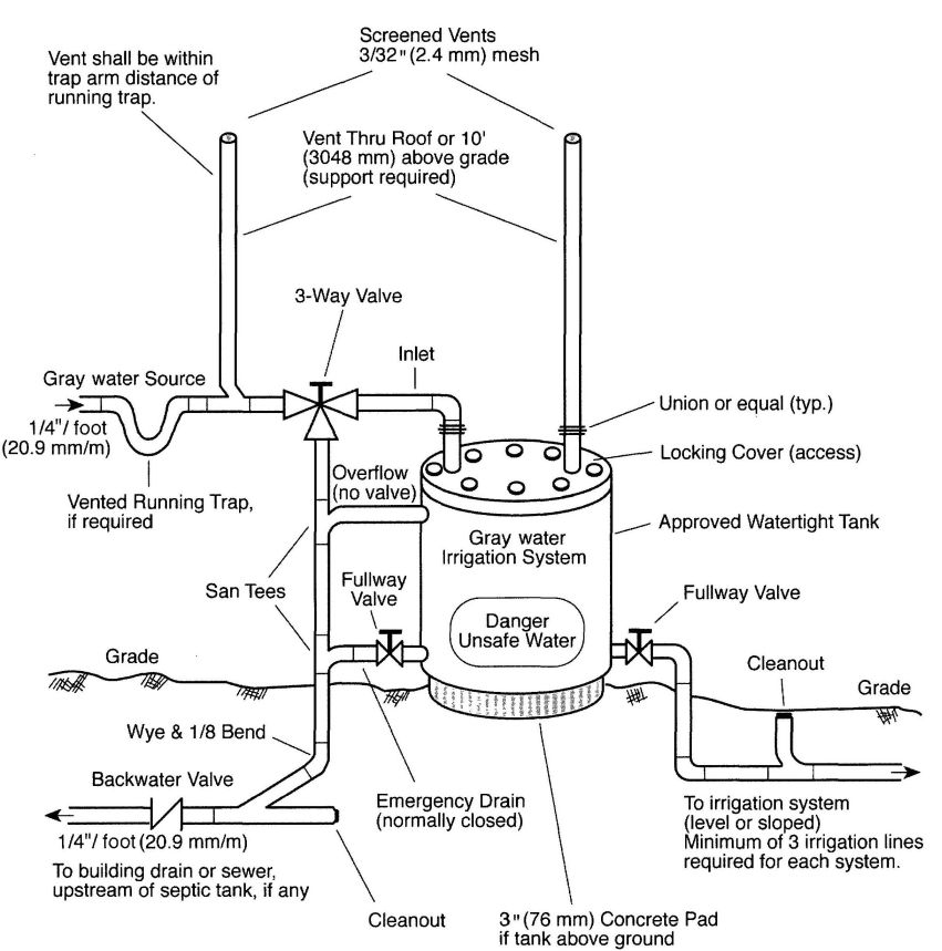
FIGURE G-1
GRAYWATER SYSTEM TANK - GRAVITY (CONCEPTUAL)
FIGURE G-2
GRAYWATER SYSTEM TANK–PUMPED (CONCEPTUAL)
FIGURE G-3
GRAYWATER SYSTEM MULTIPLE TANK INSTALLATION (CONCEPTUAL)
FIGURE G-4
GRAYWATER SYSTEM UNDERGROUND TANK–PUMPED (CONCEPTUAL)
FIGUREG-5
GRAYWATER SYSTEM TYPICAL IRRIGATION LAYOUT (CONCEPTUAL)
| Adopting Agency | BSC | SFM | HCD | DSA | OSHPD | CSA | DPH | AGR | DWR | CA | |||||||
|---|---|---|---|---|---|---|---|---|---|---|---|---|---|---|---|---|---|
| 1 | 2 | 1/AC | AC | SS | SS/CC | 1 | 2 | 3 | 4 | ||||||||
| Adopt Entire Chapter | X | X | X | X | |||||||||||||
| Adopt Entire Chapter as amended (amended sections listed below) | X | X | X | ||||||||||||||
| Adopt only those sections that are listed below | |||||||||||||||||
| Chapter/Section | |||||||||||||||||
| 2.2.6 IS 5-2006 | X | X | X | ||||||||||||||
| 1.2 IS 20-2006 | X | ||||||||||||||||
| 1.2.1 IS 20-2006 | X | ||||||||||||||||
| 1.2.2 IS 20-2006 | X | ||||||||||||||||
“The information contained in this appendix is not part of this American National Standard (ANS) and has not been processed in accordance with ANSI's requirement for an ANS. As such, this appendix may contain material that has not been subjected to public review or a consensus process. In addition, it does not contain requirements necessary for conformance to the standard.”
The following IAPMO Installation Standards are included here for the convenience of the users of the California Plumbing Code. They are not considered as a part of the California Plumbing Code unless formally adopted as such. These Installation Standards are independent, stand-alone documents published by the International Association of Plumbing and Mechanical Officials and are printed herein by the expressed written permission of IAPMO.
| Page | ||
|---|---|---|
| IS 1-2006 | Non-Metallic Building Sewers | 361 |
| IS 2-2006 | Tile-Lined Roman Bathtubs | 365 |
| IS 3-2006 | Copper Plumbing Tube, Pipe, and Fittings | 371 |
| IS 4-2006 | Tile-Lined Shower Receptors (and Replacements) | 379 |
| IS 5-2006 | ABS Building Drain, Waste, and Vent Pipe and Fittings | 383 |
| IS 6-2006 | Hubless Cast Iron Sanitary and Rainwater Systems | 387 |
| IS 7-2006 | Polyethylene (PE) Cold Water Building Supply and Yard Piping | 389 |
| IS 8-2006 | PVC Cold Water Building Supply and Yard Piping | 393 |
| IS 9-2006 | PVC Building Drain, Waste, and Vent Pipe and Fittings | 401 |
| IS 11-2006 | ABS Sewer Pipe and Fittings | 405 |
| IS 12-2006 | Polyethylene (PE) for Gas Yard Piping | 409 |
| IS 13-2006 | Protectively Coated Pipe | 413 |
| IS 15-2006 | Asbestos Cement Pressure Pipe for Water Service and Yard Piping | 415 |
| IS 18-2006 | Extra Strength Vitrified Clay Pipe in Building Drains | 419 |
| IS 20-2006 | CPVC Solvent Cemented Hot and Cold Water Distribution Systems | 421 |
| IS 21-2006 | Welded Copper and Copper Alloy Water Tube | 433 |
| IS 26-2006 | Trenchless Insertion of Polyethylene (PE) Pipe for Sewer Laterals | 439 |
| IS 27-2003 | Odor Control Systems for Water Closets | 441 |
| IS 28-2005 | Composite PEX-AL-PEX Hot and PE-AL-PE Cold Water-Distribution Systems | 445 |
| SIS 1-2003 | Flexible PVC Hose | 449 |
| SIS 2-2003 | Assembled Whirlpool Bath Appliances | 453 |
1.0 SCOPE.
1.1 Installation and material of non-metallic building sewer piping shall comply with this standard and the current edition of the Uniform Plumbing Code [UPC]TM published by the International Association of Plumbing and Mechanical Officials.
Note:The following sections of the Uniforms Plumbing Code apply to non-metallic building sewer piping. The standard may include section numbers or may omit section numbers which pertain to non-metallic sewers.
103.5.3.3 Exceptions
301.1 Minimum Standards
310.0 Workmanship
311.0 Prohibited Fittings and Practices
313.0 Protection of Piping, Materials, and Structures
315.0 Trenching, Excavation, and Backfill
316.2.3 Plastic Pipe to Other Materials
316.4 Prohibited Joints and Connections
317.0 Increasers and Reducers
Chapter 7 Sanitary Drainage
705.1 Types of Joints
705.2 Use of Joints
723.0 Building Sewer Test
2.0 GENERAL REQUIREMENTS.
2.1 After inspection of the sewer pipe, carefully backfill the treanch as prescribed by Section 315.0 of the Uniform Plumbing Code.
2.2 The same water test procedure shall apply to all non-metallic house sewer materials as required in Section 723.0 of the Uniform Plumbing Code.
Before laying non-metallic sewer pipe, prepare the bottom trench so that the piping shall lay on a firm bed throughout its entire length as required by Section 718.0 of the Uniform Plumbing Code.
3.0 PRODUCT REQUIREMENTS.
3.1 ABS OR PVC-DWV PIPE.
3.1.1 Minimum Standards.
ABS or PVC Schedule 40 DWV pipe for use in domestic sewage, excluding special waste, shall be installed in accordance with IAPMO Standards Is 5 and IS 9 (latest edition), whichever is applicable. ABS or PVC Schedule 40 DWV pipe, may be used in size 2 inch (51 mm) and larger. [UPC 301.1, 701.0]
3.1.2 Markings.
3.1.2.1 ABS Pipe. ABS pipe markings shall be in accordance with ASTM D 2661 or ASTM F 628. [UPC 716.0]
3.1.2.2 ABS Fittings. ABS fittings markings shall be in accordance with ASTM D 2661. [UPC 716.0]
3.1.2.3 PVC Pipe. PVC pipe markings shall be in accordance with ASTM D 2665. [UPC 716.0]
3.1.2.4 PVC Fittings. PVC fittings markings shall be in accordance with ASTM F 2135. [UPC 716.0]
3.1.3 Protection of Building Sewers.
ABS or PVC Schedule 40 pipe shall be installed a minimum of 1 foot (305 mm) below the surface of the finished grade. Underground installation of thermoplastic sewer pipe shall be in accordance with ASTM D 2321. [UPC 718.0]
3.1.4 Cleanouts.
Cleanouts, extended to within 1 foot (305 mm) of grade, shall be of materials listed for that use. [UPC 719.0]
3.2 PVC SEWER PIPE.
3.2.1 Minimum Standards.
3.2.1.1 Pipe.
PVC, PSM, SDR 35, ASTM D 3034 and PVC, PS-46, ASTM F 789 Non-Pressure Pipe may be used in size four (4) inches (102 mm) and larger. [UPC 301.1, 701.1]
3.2.1.2 Fittings.
All fittings shall be PVC or other listed non-metallic materials having equivalent durability and equal or greater strengths. [ PC 301.1, 701.2]
3.2.2 Types of Joints.
PVC sewer pipe shall be joined by using compression joints or by other methods recognized in the UPC. Pipe and fitting ends shall be lubricated with an approved soap jelly or soap solution to permit easy assembly. [UPC 705.1]
3.2.2.1 Use of Joints.
PVC sewer pipe shall be installed using the same type of jointing throughout, except when connecting
to existing piping, piping of other materials, in line repairs, and manholes. Transition connections to other materials shall be made by adapter fittings or a one-piece molded rubber coupling with appropriate bushings for the respective material. [UPC 705.2]
3.2.3 Markings.
3.2.3.1 PSM PVC pipe markings shall be in accordance with ASTM D 3034. [UPC 716.0]
3.2.3.2 PSM PVC fitting markings shall be in accordance with ASTM D 3034. [UPC 716.0]
3.2.3.3 PS-46 PVC pipe markings shall be in accordance with ASTM F [UPC 716.0]
3.2.3.4 PS-46 PVC pipe fitting markings shall be in accordance with ASTM F 789. [UPC 716.0]
3.2.4 PVC sewer pipe shall not be installed less than 1 foot (305 mm) below the surface of the finished grade and closer than twenty-four (24) inches (610 mm) from a building. Underground installation of thermoplastic sewer pipe shall be in accordance with ASTM D 2321. [UPC 718.0]
3.2.5 Cleanouts.
Cleanouts, extended to within 1 foot (305 mm) of grade, shall be of materials listed for such use. [UPC 719.0]
3.3 HIGH DENSITY POLYETHYLENE PIPE.
3.3.1 Minimum Standards.
3.3.1.1 Polyethylene pipe shall be manufactured in accordance with ASTM F 714 and installed in accordance with IAPMO IS 26. [UPC 301.1]
3.3.2 Types of Joints.
3.3.2.1 HDPE joints shall be made using the following method:
3.3.3 Markings.
3.3.3.1 Markings shall be in accordance with ASTM F 714. [UPC 716.0]
3.4 POLY VINYL CHLORIDE (PVC) CORRUGATED SEWER PIPE WITH A SMOOTH INTERIOR AND FITTINGS.
3.4.1 Minimum Standards.
3.4.1.1 Pipe. Corrugated PVC sewer pipe may be used in sizes four (4) (102 mm), six (6) (152 mm), eight (8) (203 mm) and ten (10) (254 mm) diameters and shall conform to ASTM F 949. [UPC 301.1]
The profile wall pipe corrugated PVC sewer pipe as intended for underground use in non-pressure applications for sanitary sewers, storm sewer, and perforated and unperforated pipes for subdrainage. [UPC 301.1]
3.4.1.2 Fittings shall be PVC or other fittings having equivalent durability or equal or greater strengths in accordance with ASTM F 949. [UPC 301.1]
3.4.2 Types and Use of Joints. Corrugated PVC sewer pipe shall be joined by Molded or Elastomeric Compression Joints or by other approved methods. Elastomeric seals (gaskets) shall meet the requirements of ASTM F 477. The lubricant used for assembly shall be as recommended by the seller and shall have no detrimental affect on the gasket or on the pipe and fittings.
The PVC cement shall comply with ASTM D 2564 and shall be used in conjunction with a primer in compliance with ASTM F 656. The solvent cement shall be used only for bushings in accordance with ASTM D 2855. [UPC 316.1, 705.1]
3.4.3 Markings.
3.4.3.1 Corrugated PVC sewer pipe markings shall be in accordance with ASTM F 949. [UPC 716.0]
3.4.3.2 Corrugated PVC fittings markings shall be in accordance with ASTM F 949. [UPC 716.0]
3.4.4 Protection of Building Sewer. Corrugated PVC sewer pipe shall not be installed less than 1 foot (305 mm) below the surface of the finished grade and closer than twenty-four (24) inches (610 mm) from a building. Underground installation of thermoplastic sewer pipe shall be in accordance with ASTM D 2321. [UPC 718.3]
3.4.5 Cleanouts. Cleanouts, extended to within 1 foot (305 mm) of grade, shall be of materials listed for such use. [UPC 719.0]
3.5 ASBESTOS CEMENT SEWER PIPE.
3.5.1 Minimum Standards.
Asbestos cement sewer pipe shall be Type II only and may be used only in sizes four (4) inches (102 mm) and larger. Its use is limited to domestic sewage. [UPC 301.1]
3.5.2 All fittings used with asbestos cement sewer pipe shall be asbestos cement or other approved non metalic materials having equivalent durability and providing fittings with equal or greater strengths. [UPC 701.2]
3.5.3 Asbestos cement sewer pipe and male and fittings shall be joined by means of a sleeve coupling and two rubber sealing rings suitable for the particular size of the pipe and fittings for which they will be used. The rubber sealing rings shall be positioned in interior grooves in the coupling.
The assembled joint shall provide the necessary compression of the rubber sealing rings to make a watertight joint. The crush strength across the assembled joint shall be equivalent to the crush strength of the pipe with which it will be used. [UPC 705.1]
3.5.3.1 The use of unmachined field-cut asbestos cement sewer pipe is permitted for necessary length adjustments and at points of connection to other piping materials. These adaptions shall be made with
either a one-piece molded rubber coupling with appropriate bushings or listed adapter fittings. [UPC 705.2]
3.5.3.2 Approved female fittings shall be provided with interior grooves in the bell ends in which rubber sealing rings, suitable for the particular size of pipe with which the fittings will be used, are placed. The compressed rubber sealing ring in the joined female (bell) fitting end shall provide a watertight joint. [UPC 705.2]
3.5.3.3 Pipe and fitting ends shall be lubricated with an approved jelly or soap solution to permit easy assembly. [UPC 705.2]
3.5.3.4 A listed one-piece molded rubber coupling with appropriate bushings may be used as an alternate means of connecting asbestos cement pipe and male end fittings. [UPC 705.2]
3.5.3.5 Transition from asbestos cement sewer pipe to another material shall be made by listed adapter fittings, or a one-piece molded coupling with appropriate bushings for the respective material. [UPC 705.1]
3.5.4 Markings.
3.5.4.1 Asbestos cement sewer pipe markings shall be in accordance with ASTM C 428. [UPC 716.0]
3.5.4.2 Each coupling sleeve of fitting markings shall be in accordance with ASTM C 428. [UPC 716.0]
3.5.5 No asbestos cement sewer pipe shall be installed less than 1 foot (305 mm) below the surface of the ground or closer than two (2) feet (610 mm) to a building. [UPC 718.3]
3.5.6 Cleanouts shall be asbestos cement or other approved materials of plug or cap type installed with rubber ring compression joints. Cleanouts, extended to within 1 foot (305 mm) of the surface, shall be of materials approved for such use. [UPC 719.0]
3.6 CONCRETE SEWER PIPE.
3.6.1 Minimum Standards.
3.6.1.1 Pipe and Fittings
Concrete sewer pipe may be used in sizes four (4) inches (102 mm) and larger. Concrete sewer pipe shall conform to ASTM C 14, Class 2. Transition to other types of sizes of pipe may be made with listed concrete pipe adapter fittings or listed one piece molded rubber coupling with appropriate bushings or increasers. [UPC 301.1]
3.6.2 Types of Joints.
Concrete sewer pipe and fittings shall be joined by means of flexible rubber sealing rings, compressed to provide water-tight joints conforming to ASTM C 443, or by listed one-piece molded rubber couplings, or hot-poured joints of listed hot-pour compounds. Portland cement joints are prohibited except for repairs or connections to existing lines constructed with such joints.
Concrete sewer pipe shall be joined by gaskets furnished by the pipe manufacturer and installed according to the manufacturer's instructions. Approved lubricant shall be used when required for the type of joint furnished. [UPC 705.1]
3.6.3 Use of Joints.
Except for points of connection to existing piping at either end of the sewer, concrete sewer pipe shall be laid using the same type of jointing throughout. [UPC 705.2]
3.6.4 Markings.
3.6.4.1 Concrete sewer pipe and fittings markings shall be in accordance with ASTM C 14. [UPC 716.0]
3.6.5 Grade, Support and Protection of Building Sewers.
Concrete sewer pipe shall be installed not less than 1 foot (305 mm) below the ground and not closer than two (2) feet (610 mm) to a building. [UPC 718.0]
3.6.6 Cleanouts.
Cleanouts shall conform to type of jointing used and cleanouts extended to within 1 foot (305 mm) of grade, shall be of materials listed for that use. [UPC 719.0]
3.7 VITRIFIED CLAY PIPE.
3.7.1 Minimum Standards.
3.7.1.1 Materials. Materials shall comply with the appropriate standard in Table 14-1 of the UPC. Vitrified clay sewer pipe, extra strength only, may be used in sizes three (3) inches (76 mm) and larger. [UPC 301.1, 701.0]
3.7.2 Types of Joints.
Vitrified clay sewer pipe and fittings shall be joined by means of preformed flexible compression joints or listed one-piece molded rubber couplings. [UPC 705.1]
3.7.2.1 Except at point of connection to existing piping at either end of the sewer, vitrified clay sewer piping shall be laid using the same type of jointing throughout. [UPC 705.1]
3.7.2.2 When installing clay pipe with flexible compression joints, the mating surfaces shall be wiped clean of dirt and foreign matter. An approved lubricant shall be applied to the joint surfaces. Spigot shall then be seated full depth into the bell. [UPC 705.1]
3.7.2.3 Listed one-piece molded rubber couplings shall be permitted for use on vitrified clay pipe and fittings, sizes three (3) inches (76 mm) through 1 foot (305 mm), [UPC 705.1]
3.7.2.4 Transition to other types of materials or sizes may be made with the use of listed one-piece molded rubber couplings with appropriate bushings or increasers. [UPC 705.1]
3.7.3 Markings.
3.7.3.1 Vitrified clay sewer pipe and fittings markings shall be in accordance with ASTM C 700. [UPC 716.0]
3.7.4 No vitrified clay sewer pipe shall be installed less than 1 foot (305 mm) below the surface of the ground. [UPC 718.3]
3.7.5 Cleanouts.
Cleanouts shall conform to the type of jointing used and cleanouts extended to within 1 foot (305 mm) of grade shall be of materials approved for their use. [UPC 719.0]
ADOPTED: 1957
REVISED: 1966, 1971, 1973, 1975, 1976, 1982, 1985, 1990, 1991, 2002, 2003, 2006
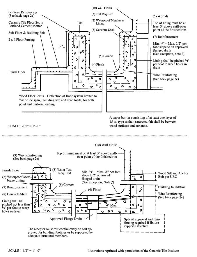

1.0 GENERAL REQUIREMENTS.
1.1 Inspection of Work – All surfaces prepared by others shall be inspected by the tile installer before starting tile work and all unsatisfactory conditions reported to the Administrative Authority. Starting tile work by the tile installer shall be considered as acceptance of surfaces prepared by others.
1.2 Surfaces – All surfaces to receive tile work shall be clean, structurally sound, and conform in every way to the local Building Code.
Note: No tile work shall proceed until the pan and drain construction has been inspected and approved by the Administrative Authority, where required.
2.0 MATERIALS
2.1 Tile Quality and Grade – Tile shall comply with American National Standard Specification for Ceramic Tile, A137.1 (equivalent to and incorporating U.S. Dept. of Commerce Simplified Practice Recommendation, R61-61 and Federal Specification SS-T-308b, Tile, Floor, Wall, and Trim Units, Ceramic).
2.2 Cement – Cement shall be portland cement type I or type II, conforming to ASTM C 150.
2.3 Sand – Sand shall be damp, clean and graded ASTM C 778.
2.4 Water – Water shall be potable.
2.5 Reinforcing shall be 3 inch × 3 inch (76 mm × 76 mm), 13 × 13 gage or 1 ½ × 2 (38 mm × 51 mm) mesh, 16 × 13 gage steel wire, conforming to ASTM A 82 and A 185.
2.6 Asphalt shall conform to Federal Specification A-A-50694 or ASTM D 1227.
2.7 Plastic Roof Cement shall conform to Federal Specification SS-C153.
2.8 Waterproof Felt Membrane – The waterproof Felt membrane shall be at least 15 lb. (6.8 kg) asphalt saturated felt, conforming to ASTM D 2626.
2.9 Plastic Membrane shall comply with ANSI A118.10.
2.10 Other Membranes – Where the Administrative Authority approves their use, non-metallic sub-pans or linings of lead sheets weighing not less than 4 lbs. per sq. foot (191.5 Pa) and copper pans of at least No. 24 B & S gage may be used.
2.11 Waterproofing Admixture – The mortar bed of the receptor shall be mixed with a waterproof admixture, approved by the Administrative Authority in the amounts allowed by such approval.
2.11.1 Currently Approved Mortar Additives.
Anti-Hydro – 1 qt. (0.95 I) per sack of cement.
Plastiment – 1 lb. (0.5 kg) of powder per sack of cement.
Plastiment – 2 oz. (56.7 g) of fluid per sack of cement.
Sika 3A – 1 qt. (0.95 I) per sack of cement
Suconem (Red Label) – 1 pint (0.47 I) per sack of cement.
3.0 INSTALLATION.
3.1 Drains – An approved type drain with sub-drain shall be installed with every such shower membrane. Flange of each sub-drain shall be accurately set exactly level with sloping sub-floor and shall be equipped with a clamping ring or other approved device to make a tight connection between the membrance and the sub-drain. The sub-drain shall have weep holes into the waste line. The drain shall be of such design that there will be not less than 2 inch (51 mm) depth from the top of the sub-drain flange to top of the strainer. A ring of absorbent material must be placed around the weep holes to keep them open when the finish materials are installed. [UPC 412.0]
3.2 Sloping Sub-Floor and Membrane – All lining materials shall be pitched not less than one quarter (¼) inch per foot (20.8 mm/m) to weep holes in the sub-drain by means of a smooth and solidly formed sloping sub-base. All such lining materials shall extend upward on the side walls of the tub to a point not less than four (4) inches (102 mm) above the top of the finished dam or threshold and shall extend outward over the top of the rough threshold and be turned over and fastened on the outside face of the rough threshold. All ledge tops within four (4) inches (102 mm) above the rough threshold shall be covered with the lining material. Non-metallic sub-pans or linings shall be built-up on the job site and shall consist of not less than three (3) layers of standard grade fifteen (15) pound (6.8 kg) asphalt impregnated roofing felt. The bottom layer shall be mopped to the formed sub-base with hot asphalt and each succeeding layer thoroughly hot-mopped to that below, on the basis of twenty (20) pounds (9.1 kg) of asphalt per layer per square. All corners shall be carefully fitted and shall be made strong and watertight by folding or lapping, and each corner shall be reinforced with suitable woven glass fiber webbing hot-mopped in place. All folds, laps, and reinforcing webbing shall extend at least four (4) inches (102 mm) in all directions from the corner and all glass fiber webbing shall be of approved type and mesh, producing a tear strength of not less than fifty (50) pounds per square inch (344.5 kPa) in either direction. Non-metallic shower sub-pans or linings may also consist of multi-layers of other approved equivalent materials suitably reinforced with glass fibers and having each layer carefully fitted and hot mopped in place on the job site as elsewhere required in this section, according to manufacturer's recommended installation procedures.
Linings shall not be nailed or perforated at any point which will be less than one (1) inch (25.4 mm) above the finished dam or threshold.
Where flexible plastic sheet membranes are used, corners shall be carefully constructed by folding or bonding of pre-fabricated reinforcing corner. Joints in flexible plastic sheeting shall be constructed with the appropriate solvent bonding liquid, bodied solvent cement, or thermal welding.
Where lead and copper pans are used as membranes, the installation shall be made in similar manner as required for felt membranes, except the asphalt moppings, and, in addition, the pans shall be insulated from all concrete and mortar surfaces and from all conducting substances, other than their connecting drain, by 15 lb. (6.8 kg) asphalt saturated felt or an approved equivalent, hot-mopped to the lead or copper pans. Joints in lead and copper pans shall not be soldered, but shall be burned or silver brazed, respectively.
3.3 Tests – Upon installation, all concrete tub shells shall be tested for water tightness by being filled to the top of the rough threshold with water for 24-hours to establish their water tightness.
3.4 Roman Bath Tub – Floor shall be of ceramic tile set in portland cement mortar, mixed in the proportion of one (1) part portland cement to four (4) parts of mortar sand by volume and shall be provided with an approved shower drain designed to make a water-tight joint at the floor. The mortar mixture shall be of such consistency that a troweled surface readily assumes a smooth, slickened surface. All concrete mortar bases shall be mixed with an approved waterproofing admixture and properly reinforced with 3 inch × 3 inch (76 mm × 76 mm) mesh, 13 × 13 gage or 1 ½ inch × 2 inch (38 mm × 51 mm) mesh, 16 × 13 gage cold drawn welded steel wire fabric located in the approximate center of the mortar bed and extending up the side walls but, in no case, less than 1 inch (25.4 mm) above the finished threshold. Corners shall be lapped and the reinforcing shall extend over the threshold and ledges.
The total thickness of the floor mortar shall not be less than 1 ¼ inch (32 mm) at any point. The tile floor shall have a minimum of 1/8 inch (3.2 mm/m) pitch and a maximum of 1/2 inch (12.7 mm/m) pitch toward the drain per foot. Bath tub walls to a minimum height to 3 inch (76 mm) and not less than 1 inch (25.4 mm) above the finished dam shall be lined with ceramic tile set in portland cement mortar, mixed with an approved water-proofing admixture.
All wood framed bases shall be designed with a maximum deflection of 1/240 of the span, including live and dead loads.
3.4.1 Note: Two stages of construction are covered – the reinforced concrete shell and the wire reinforced tile lining over the water-proof membrane.
3.4.2 Approved waterproofing membrane, mortar bed and finish construction shall conform to the general requirements of the Uniform Plumbing Code. Exception: In short sections where there is no foot traffic, the finished floor may exceed ½ inch per foot (12.7 mm/m) slope.
3.4.3 Each concrete shell shall be filled to its overflow rim with water and shall remain watertight for not less than twenty-four (24) hours before inspection and before the finish surface is installed.
3.4.4 The finish surface shall be ceramic tile installed with portland cement mortar mixed to a proper consistency in the proportion of one (1) part cement and four (4) parts mortar sand by volume and having an approved waterproofing admixture* included. Ceramic tile joints shall be thoroughly grouted with approved water-proofing grout containing an admixture.
3.4.5 The concave interior surfaces shall be such as to permit ready cleansing and all corners shall be rounded or at angles not in excess of 45°. Grout is
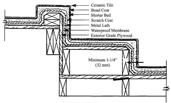
WOOD FORM
not acceptable for rounding corners. See details below on approved corners.
3.4.6 Concealed overflow or built-in waste stopper may be used if designed and approved for this application.
3.4.7 For reinforcement in center of pour, use #30 @ 8 inch (203 mm) O.C. both ways.
3.4.8 2000 P.S.I. (13,780 kPa) compressive strength concrete shall be poured monolithically and shall have an approved waterproofing admixture included*. Concrete to have not less than six (6) sacks of portland cement per batch.
3.4.9 Reinforcing wire, as specified under materials in this standard or equal, shall be wired together in a self-supporting manner. Nails shall not be used through the waterproofing membrane to fasten wire reinforcing.
*Quantities of several approved waterproofing admixtures required per sack of cement:
Anti-Hydro – 1 qt. (0.95 1) per sack of cement.
Plastiment – 1 lb. (0.5 kg) of powder per sack of cement.
Plastiment – 2 oz. (56.7 g) of fluid per sack of cement.
Sika 3A – 1 qt. (0.95 1) per sack of cement.
Suconem (Red Label) – 1 pint (0.47 1) per sack of cement.
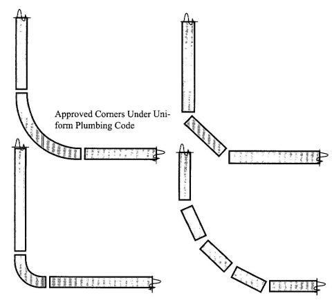
ADOPTED: 1966
REVISED: 1977, 1982, 1990, 2003, 2006
1.0 SCOPE.
1.1 Installation and material of copper tube, pipe and fittings in drainage, vent, and water systems shall comply with this standard and the current edition of the Uniform Plumbing Code [UPC]TM, published by the International Association of Plumbing and Mechanical Officials (IAPMO).
Note: The following sections of the Uniform Plumbing Code shall apply.
| 103.5.3 | Testing of systems |
| 301.1 | Minimum standards |
| 310.0 | Workmanship |
| 311.0 | Prohibited fittings and practices |
| 313.0 | Protection of piping materials and structures |
| 314.0 | Hangers and supports |
| 316.1 | Types of joints |
| 316.2 | Special joints |
| 316.4 | Prohibited joints and connections |
| 317.0 | Increasers and reducers |
| 408.4 | Closet flanges |
| 604.0 | Materials |
| 604.1 | Water piping |
| 604.2 | Water piping |
| 604.3 | Marking of tubing |
| 604.4 | Flexible water connectors |
| 604.7 | Restriction of used piping |
| 606.1.1 | Flared joints |
| 606.2.1 | Use of joints, copper water tube |
| 608.0 | Relief valve drain |
| 609.0 | Installation, inspection, testing |
| 610.0 | Size of potable piping |
| 701.1.4 | Drainage and vent piping |
| 705.3.3 | Ground joint, flared or ferrule connections |
| 707.1 | Cleanouts |
| 701.0 | Materials, drainage piping |
| 811.1 | Chemical or industrial waste piping |
| 903.0 | Materials, vent piping |
| 903.2 | Use of copper tubing |
| 1101.3 | Materials, rain water piping |
| 1105.1 | Materials, roof drains |
| Table 14-1 Standards | |
| ASME B 16.18 | Cast Copper Alloy Solder-Joint Pressure Fittings |
| ASME B 16.22 | Wrought Copper and Copper Alloy Solder-Joint Pressure Fittings |
| ASME B 16.23 | Cast Bronze Solder-Joint Drainage Fittings - DWV |
| ASME B 16.29 | Wrought Copper and Copper Alloy Solder-Joint Drainage Fittings |
| ASME B 16.50 | Wrought Copper and Copper Alloy Braze-Joint Pressure Fittings |
| ASTM B 32 | Solder Metal |
| ASTM B 42 | Seamless Copper Pipe, Standard Sizes |
| ASTM B 75 | Seamless Copper Tubes |
| ASTM B 88 | Seamless Copper Water Tube |
| ASTM B 302 | Threadless Copper Pipe, Standard Sizes |
| ASTM B 306 | Copper Drainage Tube (DWV) |
| ASTM B 813 | Liquid and Paste Fluxes for Soldering Applications of Copper and Copper Alloy Tube |
| ASTM B 828 | Standard Practice for Making Capillary Joints by Soldering of Copper and Copper Alloy Tube and Fittings |
| Appendix A | Chart A-4 Friction loss per 100 ft. (30.5m) |
2.0 PRODUCT REQUIREMENTS.
2.1 Minimum Standards.
2.1.1 Materials. Materials shall comply with the appropriate standard in Table 14-1 of the UPC. [UPC 301.1]
Note: The nominal or standard size of copper plumbing tube is always 0.125 inch (3.175 mm) or one-eighth (1/8) inch (3.175 mm) smaller than the actual outside diameter dimension of the tube. For example, 3 inch (76 mm) nominal size copper plumbing tube measures 3 1/8 inch (79 mm) O.D., ½ inch (12.7 mm) nominal size copper plumbing tube measures 5/8 inch (15.9 mm) O.D., etc.
2.1.2 Markings. Markings shall be visible for inspection. Products that are covered by this standard shall be identified in accordance with the standard found in Table 14-1. [UPC 301.1]
2.1.3 Tube and Threadless Pipe.
Water tube (Types K, L, M), drainage tube (Type DWV), and threadless pipe (TP), shall bear the
following incised marking at not over 18 inch (457 mm) intervals:
2.1.4 Pipe (Copper and Copper Alloy).
Pipe shall bear the following incised marking at not over 18 inch (457 mm) intervals:
2.1.5 Fittings.
Fittings shall bear the following markings:
2.2 Type of Joints.
2.2.1 General Information.
Copper tube and fittings may be joined in a number of ways, depending on the purpose of the system. Soldering and brazing with capillary fittings are the methods used most.
The American Welding Society (AWS) defines soldering as a joining process which takes place below 840°F (449°C) but below the melting point of the base metals. In actual practice for copper systems, most soldering is done at temperatures from about 350°F (177°C) to 550°F (288°C), while most brazing is done at temperatures ranging from 1100°C (593°C) to 1500°F (816°C). The choice between soldering or brazing will generally depend on operating conditions. Solder joints are generally used where the service temperature does not exceed 250°F (121°C), while brazed joints are used where greater tensile strength is required to resist vibration, or pressure or temperature cycling, or where system temperatures are as high as 350°F (177°C). Although brazed joints offer higher joint strength in general, the annealing of the tube and fitting which results from the higher heat used in the brazing process can cause the rated pressure of the system to be less than that of a soldered joint. This fact should also be considered in choosing which joining process to use.
Mechanical joints are used frequently for use some underground connections, for joints where the use of heat is impractical and for joints that may have to be disconnected from time to time. [UPC 316.1]
2.2.2 Fittings for Soldered, Brazed, and Mechanical Joints.
Cast fittings are available in all standard tube sizes and in a wide variety of types to cover needs for plumbing. They can be either soldered or brazed, although brazing cast fittings requires care. Wrought copper pressure fittings are also available over a wide range of sizes and types. These, too, can be joined by either soldering or brazing and wrought fittings are prefferred where brazing is the joining method. Otherwise, the choice between cast and wrought fittings is largely a matter of the user's preference and availability. According to the American Welding Society, the strength of a brazed joint will meet or exceed that of the tube and fitting being joined when the joint overlap and the depth of the filler metal penetration is a minimum of three times the thickness of the thinner base metals (tube or fitting) and a well-developed fillet (cap) is present. The strength of a brazed copper tube joint does nor vary much with different filler metals but depends on maintaining the proper clearance between the outside of the tube and the socket (cup) of the fitting. Copper tube and solder-type pressure fittings are accurately made for each other, and the tolerances permitted for each assure the capillary space will be within the limits necessary for a joint of satisfactory strength. However, the depths of the socket are considerable deeper than the three times required by AWS. Three are standards available for the manufacture of fittings made specifically for brazing, these include ASME B 16.50 and MSS SP 73. When fittings are made to these standards, they cannot be soldered. They must be brazed.
2.2.2.1 Mechanical Joints.
Flared-tube fittings provide metal-to-metal contact similar to ground joint unions; both can be easliy taken apart and reassembled. Grooved end mechanical fittings are also available in sizes 2-inches to 6-inches. Mechanical joint fittings are especially useful where residual water cannot be removed from the tube and soldering is difficult. Mechanical joints may be required where a fire hazard exists and the use of a torch to make soldered or brazed joints is not allowed. Also, soldering under wet conditions can be very difficult and mechanical joints may be preffered under such circumstances. [UPC 316.0]
2.2.3 Solders.
Most solders referenced in ASTM B 32 can be used to join copper tube and fittings in potable water systems.
Note: Users of the Uniform Plumbing Code are reminded that provisions of the Federal Safe Drinking Water Act of 1986 (SDWA), which all must obey, forbid the use of solder which contains in excess of 0.2% of lead, in potable water systems. The provisions of the act are in corporated in all ordiances, statues, state and municipal regulations by reference and by operation of law. [UPC 316.0]
The selection of a solder depends on the operating pressure and temperature of the system. Consideration should also be given to the stresses on the joint caused by thermal expansion and contraction. However, stresses due to temperature changes should not be significant in two commonly encountered cases: when tube lengths are short, or when expansion loops are used in long tube runs.
Solder is generally used in wire form, but paste-type solders are also available. These are finely granulated solders in suspension in a paste flux. These solder/flux pastes must meet the requirements of ASTM B 813. When using paste-type solders, observe these four rules:
Solders are available that contain small amounts of silver or other additives to impart special properties. Such solders may require special fluxes. The manufacturer's recommendations should be consulted regarding proper procedures and fluxes for such solders and about the expected properties.
2.2.4 Soldering Flux.
The functions of the soldering flux are to remove residual tracers of oxides, to promote wetting and to protect the surfaces to be soldered from oxidation during heating. The flux should be applied to clean surfaces and only enough should be used to lightly coat the areas to be joined.
An oxide flim may reform quickly on copper after it has been cleaned. Therefore, the flux should be applied as soon as possible after cleaning.
Careless workmanship, especially during flux applications, can result in corrosion of the tube long after the system has been installed. If excessive flux is used, the residue inside the tube can cause corrosion. In an extreme case, such residual flux can actually lead to perforation through the tube wall causing leakage. To guard against this danger, it is important (1) to choose a flux that is manufactured to ASTM B 813, and (2) to use only the minimum amount actually needed to make the joint.
2.3 Solder Joints.
2.3.1Soldering and brazing both involve basic steps, based on ASTM Standard Practice B 828, which must be executed with care and craftsmanship.
The steps are:
Each step contributes to a strong, dependable joint.
2.3.2 Measuring.
Measuring the length of each tube segment must be accurate. Inaccuracy can compromise joint quality. If the tube is too short it will not reach all the way into the socket of the fitting and a proper joint cannot be made. If the tube segment is too long there is a danger of cocking the tube in the fitting and putting strain on the system which could affect service life.
2.3.3 Cutting.
Once the tube is measured, it can be cut. Cutting can be accomplished in a number of different ways to produce a satisfactory square end. The tube can be cut with a disc-type tube cutter, a hacksaw, an abrasive wheel, or with a stationary or portable bandsaw. Care must be taken that the tube is not deformed while being cut. Regardless of the method, the cut must be square with the run of the tube so that the tube will seat properly in the fitting socket.
2.3.4 Reaming.
All pipe and tube shall be reamed to the full I.D. of the pipe and tube to remove the small burr created by the cutting operation. If this rough, inside edge is not removed erosion-corrosion may occur due to localized turbulence and high velocity.
Tools used to ream tube ends include the reaming blade on the tube cutter, half-round or round files, a pocket knife, or a suitable deburring tool. With annealed tube, care must be taken not to deform the tube end by applying too much pressure. Both the inside and the outside of the tube may require removal of the burr, especially in large diameters.
2.3.5 Cleaning.
The removal of all oxides and surfaces soil is crucial if filler metal is to flow properly into the joint. Failure to remove them can interfere with capillary action and may lessen the strength of the joint and cause failure.
Mechanical cleaning is a simple operation. The end of the tube should be lightly abraded using sand cloth or nylon abrasive pads for a distance only slightly more than the depth of the fitting socket. The socket of the fitting should also be cleaned using sand cloth, abrasive pads, or a properly sized fitting brush.
Copper is a relatively soft metal. If too much material is removed, a loose fit will result and interfere with satisfactory capillary action in making the joint. The capillary space between tube and fitting is approximately 0.004 inch (0.10 mm). Solder or brazing filler metal can fill this gap by capillary action. This spacing is critical for the filler metal to flow into the gap and form a strong joint.
Surfaces once cleaned should not be touched with bare hands or oily gloves. Skin oils, lubricating oils, and grease impair filler metal flow and wetting.
2.3.6 Fluxing.
Stir the flux before use. Flux will dissolve and remove traces of oxide from the cleaned surfaces to be joined, protect the cleaned surfaces from reoxidation during heating, and promote wetting of the surfaces by the solder. A thin, even coating of flux should be applied with fingers. Chemicals in the flux can be harmful if carried to the eyes, mouth, or open cuts.
2.3.7 Assembly and Support.
After both tube and fitting surfaces are properly fluxed, they should be assembled, making sure the tube seats against the base of the fitting socket. A slight twisting motion ensures even distribution by the flux. Remove any excess flux. Care must be taken to assure that the tube and fittings are properly supported to ensure a uniform capillary space around the entire circumference of the joint. Uniformity of capillary space will ensure good filler metal penetration if the guidelines of successful joint making are followed. Excessive joint clearance can cause the filler metal to crack under stress or vibration.
The joint is now ready for soldering. Joints prepared and ready for soldering should be completed the same day and not left unfinished overnight.
2.3.8 Heating.
WARNING: When dealing with an open flame, high temperatures, and flammable gases, safety precautions must be observed as described in the ANSI/ASC Z49.1 Standard.
Heat is generally applied using an air/fuel torch. Such torches use acetylene or an LP gas. Electric resistance tools can also be used.
Begin heating with the flame perpendicular to the tube on the bottom. The copper tube conducts the initial heat into the fitting socket for even distribution of heat in the joint area. The extent of this preheating depends upon the size of the joint. Experience will indicate the amount of time needed. Preheating of the assembly should include the entire circumference of the tube in order to bring the entire assembly up to a suitable preheat condition. However, for joints in the horizontal position, avoid directly preheating the top of the joint to avoid burning the soldering flux. The natural tendency of heat to rise will ensure adequate preheat of the top of the assembly. Next, move the flame onto the fitting socket. Sweep the flame alternately from the fitting socket back onto the tube a distance equal to the depth of the fitting socket. Touch the solder to the joint. If the solder does not melt, remove it and continue the heating process. Be careful not to overheat or to direct the flame into the fitting cup. This could cause the flux to burn and destory its effectiveness. When the solder begins to melt, the heat should be directed to the base of the cup to aid capillary action in drawing the molten solder into the fitting socket to wards the heat source.
2.3.9 Applying the Filler Metal.
For joints in the horizontal position, start applying the solder slightly off-center at the bottom of the joint. When the solder metal begins to melt from the heat of the tube and fitting do not use the torch to melt the solder; push the solder straight into the joint while keeping the torch at the base of the fitting socket and slightly ahead of the point of application of the solder. Continue this technique across the bottom of the fitting and up the side to the top of the fitting. Return to the beginning, overlapping slightly by re-melting the solder at the point and proceed up the other side to the top, again overlapping slightly.
For joints in the vertical position, a similar sequence of overlapping passes should be made, starting wherever is convenient. Molten solder will be drawn into the joint by capillary action regardless of whether the solder is being fed upward, downward or horizontally. IMPORTANT: Always remember to let the heat lead the alloy. Do not apply the filler metal in front of the heat.
2.3.10 Cooling and Cleaning.
After the joint has been completed, natural cooling is best. Shock cooling with water may cause
unnecessary stress on the joint and result in eventual failure. When cool, clean off any remaining flux with a wet rag.
2.3.11 Testing.
Test all completed assemblies for joint integrity following the procedures described in the body of this code. Completed systems should be flushed to remove excess flux and debris as soon as possible after completion.
2.4 Brazed Joints.
2.4.1 Brazing is another commonly used method for joining copper tube. Making brazed joints is similar to making soldered joints with respect to measuring, cutting, reaming, cleaning, assembly, and support. And as in soldering, the brazing filler metal is melted by the heat of the tube and fitting and drawn into the joint by capillary action.
The major differences between soldering and brazing are the:
2.4.2 Brazing Flux.
The fluxes used for brazing copper joints are different in composition from soldering fluxes. The two types cannot be used interchangeably. Unlike soldering fluxes, brazing fluxes are water based. Similar to soldering fluxes, brazing fluxes dissolve and remove residual oxide from the metal surfaces, protect the metal from reoxidation during heating and promote wetting of the surfaces to be joined by the brazing filler metal.
Fluxes also provide the craftsman with an indication of temperature. Application of the flux is the same as when soldering. If the outside of the fitting and the heat-affected area of the tube are covered with flux (in addition to the end of the tube and the cup), oxidation will be prevented and the apperance of the joint will be greatly improved.
2.4.3 Brazing Filler Metals.
Brazing filler metals suitable for joining copper tube systems are of two classes. Classified according to their components, they are: BCuP (Brazing-Copper-Phosphorus) and BAg (Brazing-Sliver).
BCuP filler metals are prefferred for joining copper tube and fittings if codes and construction specifications allow it. The phosphorus in them acts as a fluxing agent and the lower percentage of sliver makes them relatively low cost. When using copper tube, wrought copper fittings, and BCuP brazing filler metal, fluxing is optional. However, when cast fittings are brazed, flux must be used.
2.4.4 Heating.
WARNING: When dealing with an open flame, high temperatures, and flammable gases, safety precautions must be observed as described in the ANSI/ASC Z49.1 Standard. Oxy/fuel torches are generally used for brazing because of their higher temperatures. However, recent innovations in tip design make air/fuel torches useful for brazing on a wide range of sizes for brazing.
The heating operation is the same as for soldering. Heat the tube first, beginning about one inch from the edge of the fitting, sweeping, the flame around the tube in short strokes at right angles to the axis of the tube. It is very important that the flame be in motion and not remain on any one point long enough to damage the tube. Switch the flame to the fitting at the base of the fitting socket. Heat uniformly, sweeping the flame from the fitting to the tube. Avoid excessive heating of case fittings or they may crack.
2.4.5 Applying Brazing Filler Metal.
Apply the brazing filler metal at the point where the tube enters the socket of the fitting. When the proper temperature is reached, the filler metal will flow readily into the space between the tube and fitting socket, drawn in by the natural force of capillary action.
Keep the flame away from the filler metal itself as it is fed into the joint. The temperature of the tube and fitting at the joint should be high enough to melt the filler metal. Keep both the tube and fitting heated by moving the flame back and forth from one to the other as the filler metal is drawn into the joint.
When the joint is properly made the filler metal will be drawn into the fitting socket by capillary action, and a continuous fillet (cap) of filler metal will be visible completely around the joint. To aid in the development of this fillet during brazing, the flame should be kept slightly ahead of the pint of filler metal application.
When brazing horizontal joints, it is preferable to first apply the filler metal slightly off-center of the bottom of the joint, proceeding across the bottom of the joint and continuing up the side to the top of the joint. The return to the beginning point, overlapping slightly. This procedure is identical to that used for soldering. Also, similar to the soldering process, make sure the operations overlap.
On vertical joints, it is immaterial where the joint is made. If the opening of the fitting socket is pointing down, care should be taken to avoid over-heating the tube, as this may cause the brazing filler metal to run down the outside of the tube.
If the filler metal fails to flow, or has the tendency to ball-up, it indicates either that there is oxide on
the surfaces being joined or that the parts to be joined are not hot enough. If the filler metal refuses to enter the joint, the fitting cup is not hot enough. Most poorly made braze joints result from either the tube or the fitting not being hot enough. If filler metal tends to flow over the outside of either part of the joint, it indicates that part is overheated in comparison to the other. When the joint is completed, a continuous fillet should be visible completely around the joint.
Larger diameter tube is more difficult to heat to the desired temperature. The use of a heating tip or rosebud may be necessary to maintain the proper temperature over the area being brazed. Once total heat control is attained, follow the same procedures used for smaller tube.
2.4.6 Cooling and Cleaning.
When the brazed joint is finished, allow it to cool naturally. Flux residues and some oxides formed by heating can be removed by washing with hot water and brushing with a stainless steel wire brush.
2.4.7 Testing.
Test all completed assembles for joint integrity following the procedures described in the body of this code. Completed systems should be flushed to remove excess flux and debris as soon as possible after completion.
2.4.8 Purging.
Some installations, such as medical gas, high-purity gas, and ACR systems, require the use of an inert gas during the brazing process. The purge gas displaces oxygen from the interior of the system while it is being subjected to the high temperatures of brazing and therefore eliminates the possibility of oxide formation on the interior of the tube surface.
2.5 Flared Joints.
2.5.1 Flared Joints with Impact Flaring Tools.
Step 1 Cut the tube to the required length.
Step 2 Remove all burrs. This is very important to assure metal-to-metal contact.
Step 3 Soft temper tube, if deformed, should be brought back to roundness with a sizing tool. This tool consists of a plug and sizing ring.
Step 4 Slip the coupling nut over the end of the tube.
Step 5 Insert flaring tool into the tube end.
Step 6 Drive the flaring tool by hammer strokes, expanding the end of the tube to the desired flare. This requires a few moderately light strokes.
Step 7 Assemble the joint by placing the fitting squarely against the flare. Engage the coupling nut with the fitting threads. Tighten with two wrenches, one on the nut and one on the fitting.
2.5.2 Flared Joints with Screw-Type Flaring Tools.
Steps 1-4 Same as for impact flaring previously described.
Step 5 Clamp the tube in the flaring block so that the end of the tube is slightly above the face of the block.
Step 6 Place the yoke of the flaring tool on the block so that the beveled end of the compressor cone is over the tube end.
Step 7 Turn the compressor screw down firmly, forming the flare between the chamber in the flaring block and the beveled compressor cone.
Step 8 Remove the flaring tool. The joint can now be assembled as in Step 6 for impact flaring.
2.6 Sizing, Velocity.
To avoid excess system noise and the possibility of erosion-corrosion, flow through copper tube systems should not exceed velocities of 8 feet per second for cold water and 5 feet per second in hot water up to approximately 140°F (60°C) [UPC 610.0]
In systems where water temperatures routinely exceed 140°F (60°C), lower velocities such as 2 to 3 feet per second should not be exceeded. In addition, where ½-inch and smaller tube sizes are used, to guard against localized high velocity turbulence due to possible faulty workmanship (e.g. burrs at tube ends which were not properly removed) or unusually numerous, abrupt changes in flow direction, lower velocities should be considered.
Due to constant circulation and elevated water temperatures, particular attention should be paid to velocities in circulation hot water systems. Both the supply and return piping should be sized such that the maximum velocity does not exceed the above recommendations. Care should be taken to ensure that the circulating pump is not oversized and the return piping is not undersized, both common occurrences in installed copper piping systems.
3.0 GENERAL INFORMATION.
3.1 It is not possible to cover all the variables of a plumbing system; however, the following information may prove helpful:
Expansion Loops – Copper tube, like all piping materials, expands and contracts with temperature changes. Therefore, in a copper tube system subjected to excessive temperature changes, the line tends to buckle or bend when it expands unless compensation is built into the system. Severe stresses on the joints may also occur. Such stresses, buckles, or bends are prevented by the use of expansion
joints or by installing offsets, “U” bends, coil loops, or similar arrangements in the tube assembly. These specially shaped tube segments take up expansion and contraction without excessive stress. The expansion of a length of copper tube may be calculated from the formula:
Temperature Rise (°F) × Length (feet) × 12 (inches per foot) × Expansion Coefficient (in. per in. per °F) = Expansion (inches), or
Temperature Rise (°C) × Length (meter) × 1000 (mm per meter) × Expansion Coefficient (mm per mm per °C) = Expansion (mm).
Calculations for expansion and contraction should be based on the average coefficient of expansion of copper, which is 0.0000094 per °F (1.692 × 10⁻⁵ per °C), between 70°F (21°C) and 212°F (100°C). For example, the expansion of each 100 feet (3048 mm) of length of any size tube heated from room temperature (70°F) (21°C) to 170°F (77°C) (a 100°F (38°C) rise) is 1.128 inches (28.7 mm).
100° × 100 ft. × 12 in./ft. × 0.0000094 in./in./°F = 1.128 in., or
55.6° × 30.48 m × 1000 mm/m × 1.692 × 10⁻⁵ mm/mm/°C = 28.7 mm
3.2 Tube Supports - See Table 3-2 and Section 314.0 in the Uniform Plumbing Code.
3.3 Bending.
3.3.1 Copper tube, properly bent, will not collapse on the outside of the bend and will not buckle on the inside of the bend. Tests demonstrate that the bursting strength of a bend copper tube can be greater than it was before bending. Because copper is readily formed, expansion loops and other bends necessary in an assembly are quickly and simply made if the proper method and equipment are used. Simple hand tools employing mandrels, dies, forms, and fillers, or power-operated bending machines are used.
Both annealed tube and bending-temper tube can be bent with hand benders. The proper size bender for each size tube must be used. Usually the size of the tool corresponds to the nominal outside diameter of the tube, not the standard tube size. For a guide to the typical bend radii, see the following bending guide for copper tube.
ADOPTED: 1969
REVISED: 1973, 1975, 1987, 1989, 1993, 2000, 2003, 2006
| TUBE SIZE, | TUBE TYPE | TEMPER | MINIMUM BEND RADIUS, | TYPE OF BENDING EQUIPMENT | ||
|---|---|---|---|---|---|---|
| INCHES | (mm) | INCHES | (mm) | |||
| *When bending by hand, without the use of bending equipment, a circular wooden disc is used. The radius of the disc should be about ¼ to ½ inch less than the minimum bend radius shown. | ||||||
| ¼ | (6.4) | K, L | Annealed | ¾ | (19.1) | Lever type |
| 3/8 | (9.5) | K, L | Annealed | 1½ | (38) | Lever or gear type |
| 3 | (76) | None; by hand* | ||||
| K, L, M | Drawn | 1¾ | (44) | Gear type | ||
| ½ | (12.7) | K, L | Annealed | 2¼ | (57) | Lever or gear type |
| 4½ | (114) | None; by hand* | ||||
| K, L, M | Drawn | 2½ | (64) | Gear type | ||
| ¾ | (19.1) | K, L | Annealed | 3 | (76) | Lever or gear type |
| K | 4½ | (114) | None; by hand* | |||
| L | 6 | (152) | None, by hand* | |||
| K | Drawn | 3 | (76) | Gear type | ||
| K,L | 4 | (102) | Heavy-duty gear type | |||
| 1 | (25.4) | K, L | Annealed | 4 | (102) | Gear type |
| 7½ | (191) | None; by hand* | ||||
| 1¼ | (32) | K, L | Annealed | 9 | (229) | None; by hand* |
FORWARD
This standard specification for the installation of tile-lined shower receptors is the result of extensive study and research by the following:
Ceramic Tile Institute of America
Associated Tile Contractors of Southern California, Inc.
Tile Layers Local No. 18 of I.U.B.A.C, United States and Canada
Tile Helpers Local No. 18 of I.U.B.A.C., of the United States and Canada
APPROVED CONSTRUCTION OF TILE-LINED SHOWER RECEPTORS
STANDARD SPECIFICATION FOR THE INSTALLATION OF TILE-LINED SHOWER RECEPTORS
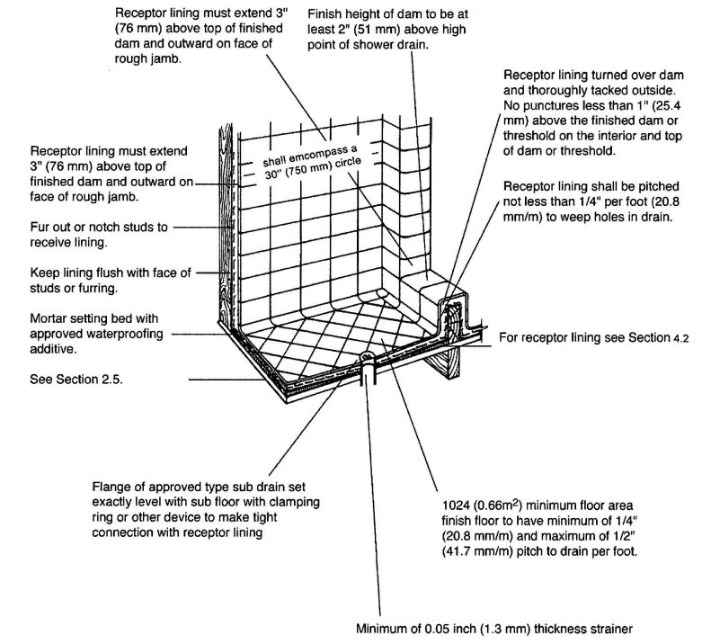
FIGURE 1
1.0 SCOPE.
1.1 Installation and material of tile-lined shower receptors shall comply with this standard and the current edition of the Uniform Plumbing Code [UPC]™, published by the International Association of Plumbing and Mechanical Officials (IAPMO).
Note: The following sections of the Uniform Plumbing Code shall apply.
| 411.1 | Floor drains |
| 411.5 | Shower receptors |
| 411.6 | Shower receptor approval |
| 411.7 | Shower compartments |
| 411.8 | On-site built-up shower |
| 411.9 | Floors of public shower rooms |
2.0 GENERAL REQUIREMENTS.
2.1 Inspection of Work. All surfaces prepared by others shall be inspected by the tile installer be fore starting tile work and all unsatisfactory conditions reported to the Administrative Authority. Starting tile work by the tile installer shall be considered as acceptance of surfaces prepared by others.
2.2 Surface. All surfaces to receive tile work shall be clean, structurally sound, and conform in every way to the local building code.
Note: No tile work shall proceed until the pan and drain construction has been inspected and approved by the Administrative Authority, where required.
3.0 PRODUCT REQUIREMENTS.
3.1 Materials.
3.1.1 Tile Quality and Grade – Tile shall comply with American National Standard Specification for Ceramic Tile, A137.1 (equivalent to and incorporating U.S. Dept. of Commerce Simplified Practice Recommendation, R61-61 and Federal Specification SS-T-308b, Tile, Floor, Wall, and Trim Units, Ceramic), or CTI 69.5.
3.1.2 Cement. Cement shall be portland cement type I or type II, conforming to ASTM C 150.
3.1.3 Sand. Sand shall be damp, clean and graded ASTM C 778.
3.1.4 Water. Water shall be potable.
3.1.5 Reinforcing shall be 2.5 lbs. per sq. yard (1.1 kg per m2) or greater galvanized metal lath conforming to ANSI A42.3 or 2 inches × 2 inches (51 mm × 51 mm), 16/16 gage or 3 inches × 3 inches (76 mm × 76 mm) mesh, 13 × 13 gage or 1 ½ inches × 2 inches (38 mm × 51 mm) mesh, 16 × 13 gage steel, wire conforming to ASTM A 82 and ASTM A 185.
3.1.6 Asphalt shall conform to Federal Specification A-A-50694 OR ASTM D 1227.
3.1.7 Plastic Roof Cement shall conform to Federal Specifications SS-C-153.
3.1.8 Water Resistant Felt Membrane. The water resistant felt membrane shall be at least 15 lb. (6.8 kg) asphalt saturated felt conforming to ASTM D 2626.
3.1.9 Plastic Membrane shall comply with ANSI A118.10.
3.1.10 Other Membranes – Where the Administrative Authority approves their use, non-metallic sub-pans or linings or lead sheets weighing not less than 4 lbs. per sq. foot (191.5 Pa) and copper pans of at least No. 24 B & S gage (Brown & Sharp 0.0201 inches) or greater in thickness may be used.
3.1.11 Waterproofing Admixture – The mortar bed of the receptor shall be mixed with a waterproof admixture approved by the Administrative Authority in the amounts allowed by such approval.
3.2 CURRENTLY APPROVED MORTAR ADDITIVES
Anti-Hydro—1 qt. (0.95 1) per sack of cement.
Plastiment—1 lb. (0.5 kg) of powder per sack of cement.
Plastiment—2 oz. (56.7 g) of fluid per sack of cement.
Sika 3A—1 qt. (0.95 I) per sack of cement.
Suconem (Red Label)—1 pint (0.47 I) per sack of cement.
4.0 INSTALLATION REQUIREMENTS.
4.1 Shower Drains – An approved type shower floor drain with sub-drain shall be installed with every such shower membrane. Flange of each sub-drain shall be accurately set exactly level with sloping sub-floor and shall be equipped with a clamping ring or other approved device to make a tight connection between the membrane and the sub-drain. The sub-drain shall have weep holes into the waste line. The weep holes located in the subdrain clamping ring shall be protected from becoming clogged during the placement of finish materials. The drain shall be of such design that there will be not less than 2″ (51 mm) depth from the top of the sub-drain flange to top of the strainer. Unless otherwise approved by the Administrative Authority, drains shall be located in the approximate center of the shower area. [UPC 411.6]
4.2 Sloping Sub-Floor and Shower Membrane All lining materials shall be pitched one quarter (¼) inch per foot (20.8 mm/m) to weep holes in the sub-drain by means of a smooth and solidly formed
sloping sub-base. All such lining materials shall extend upward on the side walls and rough jambs of the shower opening to a point not less than three (3) inches (76mm) above the top of the finished dam or threshold and shall extend outward over the top of the rough threshold and be turned over and fastened on the outside face of both the rough threshold and the jambs.
4.2.1 Non-metallic shower sub-pans or linings may be built-up on the job site of not less than three (3) layers of standards grade fifteen (15) pound (6.8 kg) asphalt impretgnated roofing felt. The bottom layer shall be fitted to the formed sub-base and each succeding layer thoroughly hot-mopped to that below, with hot asphalt conforming to Fed. Spec. SS-A0666 Type Z, Grade 2, Class A on the basis of twenty (20) pounds (9.1 kg) of asphalt per layer per square. All corners shall be carefully fitted and shall be made strong and water-tight by folding or lapping, and each corner shall be reinforced with suitable webbing hot-mopped in place. All folds, laps, and reinforcing webbing shall extend at least four (4) inches (102 mm) inches (102mm) in all directions from the corner and all webbing shall be of approved type and mesh, producing a tensile strength of not less than fifty (50) pounds per square inch (344.5 kPa per square meter) in either directions.
4.2.2 Non-metallic shower sub-pans or linings may also consist of single or multi-layers of other approved equivalent materials, suitably reinforced and carefully fitted in place on the job site, as elsewhere required in this section according to manufacturer's recommended installation procedures.
Where flexible plastic sheet membrances are used, corners shall be carefully constructed by folding or bonding of prefabricated reinforcing corner. Joints in flexible plastic sheeting shall be constructed with the appropriate solvent bonding liquid, bodied solvent cement, or thermal welding.
4.2.3 Where lead and copper pans are used as membranes, the installation shall be made in similar manner as required for felt memberances except the sphalt moppings, and in addition the pans shall be insulated from all concrete and mortar surfaces and from all conducting substances other than their connecting drain by 15 lb. (6.8 kg) asphalt saturated felt or an approved equivalent hot mopped to the lead or copper pan. Joints in lead and copper pans shall not be soldered, but shall be burned or silver brazed respectively.
4.2.4 All linings shall be properly recessed and fastened to approved backing so as not to occupy the space required for the wall covering and shall not be nailed or perforated at any point which will be less than one (1) inch (25.4 mm) above the finished dam or threshold.
4.3 Tests. Upon installation, all linings shall be tested for water tightness by being filled to the top of the rough threshold with water for a period of time sufficient to established their water tightness. (Usually twenty-four (24) hours with no loss of water. See the local Administrative Authority for exact time limit.)
A test plug shall be so placed that both the upper and under sides of the lining shall be subjected to test at its point of contact with the sub-drain. When the test plug is removed, all of the test water shall drain out by gravity through the weep holes. A ring of non-absorbent material must be placed around the weep holes to keep them open when the finish materials are installed.
4.4 Receptor. Shower floor shall be of ceramic tile set in portland cement mortar mixed in the proportion of one (1) part portland cement to four (4) parts of mortar sand by volume and shall be provided with an approved shower drain designed to make a water-tight joint at the floor. The mortar mixture shall be of such consistency that a troweled surface readily assumes a smooth screeded surface. All concrete mortar bases shall be mixed with an approved waterproofing admixture and properly reinforced with 2.5 lbs. per square yard (1.1 kg per square m) or more galvanized metal lath or 2 inches × 2 inches (51 mm × 51 mm), 16/16 gage or 3 inches × 3 inches (76 mm × 76 mm) mesh, 13 × 13 gage or 1½inches × 2 inches (38 mm × 51 mm) mesh, 16 × 13 gage cold drawn welded steel wire fabric located in the approximate center of the mortar bed and extending at least 3 inches (76 mm) at any point. The finished floor shall be not less than 2 inches (51 mm) measured from the top surface of the memberance. The high point of the title floor shall be not less than 2 inches (51 mm) or more than 9 inches (229 mm) below the top of the finished dam and shall have a minimum of ¼ inch (6.4 mm/m) and a maximum of ½ inch (19.1 mm/m) pitch per foot toward the drain. Shower walls to a minimum height of 3 inch (76 mm) and not less than 1 inch (25.4 mm) above the finished dam shall be lined with ceramic tile set in portland cement mortar.
4.5 Floors of public shower rooms shall have a nonskied surface and shall be drained in such a manner that waste water from one bather will not pass over areas occupied by other bathers. Gutters in public or gang shower rooms shall have rounded corners for easy cleaning and shall be sloped not less than two (2) percent toward drains. Drains in such gutters shall be spaced not more than eight (8) feet (2,438 mm) from side walls or more than sixteen (16) feet (4,877 mm) apart.
4.6 Shower walls, including shower walls over bath tubs, shall be constructed of dense, non-absorbent
waterproof materials, such as ceramic tile set in portland cement mortar or approved cementitious backer unit when no materials are adversely affected by moisture to a height of not less than six (6) feet (1,829 mm) above the floor.
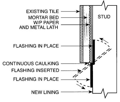
FIGURE 2
ADOPTED: 1966
REVISED: 1977, 1982, 1990, 1992, 1996, 2003, 2006
1.0 SCOPE.
1.1 This installation standard shall apply to ABS building drain, waste and vent systems as governed by the Uniform Plumbing Code. Material Standard ASTM D 2661, “Standard Specification of Acrylonitrile-Butadience-Styrene (ABS) Schedule 40 Plastic Drain, Waste and Vent Pipe and Fittings,” or ASTM F 628,“Acrylonitrile-Butadiene-Styrene (ABS) Schedule 40 Plastic, Drain, Waste and Vent Pipe with a Cellular Core,” shall form a part of this standard.
1.2 Installation, materials and inspection shall comply with the current edition of the Uniform Plumbing Code [UPC]TM as published by the International Association of Plumbing and Mechanical Officials and shall also comply with this standard.
Note: The Building Official shall be consulted about penetration of fire separations, height and area or other limitations.
Note: The following sections of the Uniform Plumbing Code apply.
| *Although referenced in this standard, some of the fittings shown in the standard are not acceptable under the Uniform Plumbing Code. | |
| 101.4.1.1 | Repair and Alterations |
| 103.5 | Inspections |
| 203.0 | Definition ABS |
| 301.1 | Minimum Standards |
| 311.8 | Screwed Fittings |
| 310.0 | Workmanship |
| 311.0 | Prohibited Fittings and Practices |
| 313.0 | Protection of Piping, Materials and Structures |
| 314.0 | Hangers and Supports |
| 316.1.1 | Threaded Joints |
| 316.1.6 | Type of Joints— Solvent Cement Plastic Pipe Joints |
| 316.2.3 | Plastic Pipe to Other Material |
| 316.3.1 | Flanged Fixture Connections |
| 316.4 | Prohibited Joints and Connections |
| 317.0 | Increasers and Reducers |
| 408.4 | Closet Flanges |
| 701.0 | Materials(Drainage) |
| 707.1 | Cleanout Fittings |
| 903.0 | Materials(Venting) |
| 903.3 | Straining or Bending Pipe |
| 1003.0 | Traps Described |
| 1101.3 | Materials Uses |
| Table 14-1 | |
| Pipe and Fittings | ASTM D 2661 ASTM D 3311 ASTM D 2122 ASTM F 402 ASTM F 628 |
ABBREVIATIONS
| ASTM | American Society for Testing and Materials |
| IAPMO | International Association of Plumbing and Mechanical Officials |
| UPC | Uniform Plumbing Code |
2.0 PRODUCT REQUIREMENTS.
2.1 Minimum Standards.
2.1.1 Pipe.
ABS pipe is furnished in straight lengths. The pipe is black in color. The pipe wall is the same thickness as that of Schedule 40 (IPS) standard steel pipe.
ABS pipe marking shall be in accordance with ASTM D 2661 or ASTM F 628. [UPC 301.1.2, 716.0]
2.1.2 Fittings.
Fittings are black. Refer to Tables in ASTM D 2661 and ASTM D 3311 for dimensions and tolrances for pipe, fitting sockets, and laying lengths.
ABS fittings markings shall be in accordance with ASTM D 2661 or ASTM F 628. [UPC 301.1.2, 701.0, 903.0]
2.1.3 Solvent Cement.
Solvent cement shall be as specified in ASTM D 2235. Solvent cement labels shall be in accordance with ASTM D 2235.
2.2 Protection of Piping.
2.2.1 Storage.
Pipe and fittings should not be stored in direct sunlight. However, exposure to direct sunlight during normal construction periods is not considered harmful. Pipe shall be stored in such a manner as to prevent sagging or bending.
Although referenced in this standard, some of the fittings shown in the standards are not acceptable under the Uniform Plumbing Code.
2.2.2 Expansion And Contraction.
Thermal expansion and contraction of plastic drain waste and vent systems shall be taken into consideration. Thermal expansion and contraction may be controlled by several methods: offset, expansion joints, or restraints. Regardless of methods utilized, certain conditions shall be met.
DWV installations with frequent changes in direction will compensate for thermal expansion and contraction. Expansion joints may be utilized in vertical straight runs in excess of thirty (30) feet (9,144mm) provided they are installed per manufactuer's installation instructions.
Except piping buried below ground, horizontal and vertical piping should be installed with restraint fittings or a minimum twenty-four (24) inches (610 mm) 45° offset every thirty (30) feet (9144 mm).
Thermal expansion for installations subject to temperature changes may be determined from Table 1. The linear expansion shown is independent of the diameter of the pipe. [UPC 313.0]
2.2.3 Exposed Piping.
Piping shall not be exposed to direct sunlight. Exception: Vent piping through roof. Plumbing vents through roof, exposed to sunlight, shall be protected by water base synthetic latex paints. Adequate support shall be provided where ABS piping is exposed to wind, snow, and ice loading.
2.2.4 Protection From Damage.
Piping passing through wood studs or plates shall be protected from puncture by steel nail plates not less than 18 gauge. Piping shall be protected from concrete form oil. [UPC 313.9]
2.2.5 Anti-Freeze Protection.
Anti-Freeze Protection – ABS pipe and traps can be protected from freezing by the use of one of the following solutions or mixtures:
The salt solutions are effective to approximately 10°F (-12°C). If lower temperatures are anticipated, the pipe should be drained are glycerol solution should be used. [UPC 313.6]
2.2.6 Piping Installed in Fire Resistive Construction.
All piping penetrations of fire resistance rated walls, partitions, floors, floor/ceiling assemblies, roof/ceiling assemblies, or shaft enclosures shall be protected in accordance with the requirements of the California Building Code and IAPMO Installation Standards. [UPC 313.7]
2.3 Hangers and Supports.
2.3.1 Abrasion.
Hangers and straps shall not compress, distort, cut, or abrade the piping and shall allow free movement of pipe. Pipe exposed to damage by sharp surfaces shall be protected. [UPC 314.0]
2.3.2 Support.
Support all piping at intervals of not more than four (4) feet (1,219 mm), at end of branches, and at change of direction or elevation. Support shall allow free movement, but shall restrict upward movement of lateral runs so as not to create reverse grade. Vertical piping shall be supported at each story or floor level. Alignment of vertical piping shall be maintained between floors with the use of a mid-story guide. Support trap arms in excess of three (3) feet (914 mm) in the length as close as possible to the trap. Closet rings shall be securely fastened with corrosive resistant fasteners to the floor with the top surface one-quarter (¼) inch (6.4 mm) above the finish floor. [UPC 314.0]
2.4 Traps.
2.4.1 Connection to Traps.
Traps shall be connected by means of listed trap adapters. [UPC 1003.0]
2.5 Joints.
2.5.1 Caulked Joints.
Make connections or transitions to bell-and-spigot cast iron soil pipe and fitting, and to bell-and-spigot pipe and fittings of other materials with listed mechanical compression joints designed for this use, or caulked joints made in an approved manner. In caulking, pack the joint with oakum or hemp and fill with molten lead to a depth of not less than (1) inch (25.4 mm). Allow a period of four (4) minutes for cooling, following which, caulk the lead at the inside and outside edges of the joint. Lead shall not be overheated. Heat lead to melting point only. [UPC 705.1]
Note: Caulked joints should be avoided if possible.
2.5.2 Solvent Cement Joints.
2.5.2.1 Selection. Solvent cement shall be recommended for ABS by the manufacturer. Follow manufactuer’s recommendations for types of solvent cement for such conditions as temperature over 100° F(38°C), or humidity over 60%. [UPC 316.1.6]
| Length (feet) | 40°F | 50°F | 60° | F70°F | 80°F | 90°F | 100°F |
|---|---|---|---|---|---|---|---|
| 20 | 0.536 | 0.670 | 0.804 | 0.938 | 1.072 | 1.206 | 1.340 |
| 40 | 1.070 | 1.340 | 1.610 | 1.880 | 2.050 | 2.420 | 2.690 |
| 60 | 1.609 | 2.010 | 2.410 | 2.820 | 3.220 | 3.620 | 4.020 |
| 80 | 2.143 | 2.680 | 3.220 | 3.760 | 4.290 | 4.830 | 5.360 |
| 100 | 2.680 | 3.350 | 4.020 | 4.700 | 5.360 | 6.030 | 6.700 |
| Length(mm) | 4°C | 10°C | 16°C | 21°C | 27°C | 32°C | 38°C |
|---|---|---|---|---|---|---|---|
| 6096 | 13.6 | 17.0 | 20.4 | 23.8 | 27.2 | 30.6 | 34.0 |
| 12192 | 27.2 | 34.0 | 40.8 | 47.8 | 52.1 | 61.5 | 68.3 |
| 18288 | 40.9 | 51.1 | 61.2 | 71.6 | 81.8 | 92.0 | 102.1 |
| 24384 | 54.4 | 68.1 | 81.8 | 95.5 | 110.0 | 122.7 | 136.1 |
| 30480 | 68.1 | 85.1 | 102.1 | 119.4 | 136.1 | 153.2 | 170.2 |
| Example: | |
| Highest Temperature expected | 100°F (38°C) |
| Lowest Temperature expected | 50°F (10°C) |
| 50°F (10°C) |
Length of run – 60 feet (18,288 mm) from chart, read 2.010 inches (51 mm) linear expansion that must be provided for.
2.5.2.2 Handling (to maintain effectiveness). Solvent cement containers no larger than 1 gallon (3.8 liters) should be used in the field (to avoid thickening due to evaporations). Keep container closed and in the shade when not in use. Keep application submerged in solvent cement between application. When solvent cement becomes thicker, THROW IT AWAY. Solvent cement shall NOT be thinned.
2.5.2.3 Size of Applicator. Applicator should be about one half the pipe diameter. Do not use small applicator on large pipes. Ordinary pure bristle paint brust or applicators furnished with product are satisfactory.
2.5.2.4 Application. Solvent cement shall be applied deliberately, but without delay (two people may be needed to make large joints). Use special care when temperature is over 100°F (38°C) or humidity is over 60%.
2.5.3 SAFETY REQUIREMENTS AND PRECAUTIONS.
2.5.3.1 General. Solvents contained in ABS plastic pipe cements are classified as airborne contaminants and flammable and combustible liquids. Precautions listed in this appendix should be followed to avoid injury to personnel and the hazard of fire.
2.5.3.2 Safety Precautions. Prolonged breathing of solvent vapors should be avoided. When pipe and fittings are being joined in partially enclosed areas, a ventilating device should be used in such a manner to minimize the entry of vapors into the breathing areas.
2.5.3.3 Solvent cement should be kept away from all sources of ignition, heat, sparks and open flame.
2.5.3.4 Containers for Solvent cements should be kept tightly closed except when the cement is being used.
2.5.3.5 All rags and other materials used for mopping up spills should be kept in a safety waste receptacle which should be emptied daily.
2.5.3.6 Most of the solvents used in ABS pipe cements can be considered eye irritants and contact with the eye should be avoided for it may cause eye injury. Proper eye protection and the use of chemical goggles or face shields is advisable where the possibility of splashing exists in handling solvent cements. In case of eye contact, flush with plenty of water for 15 minutes and call a physician immediately.
2.5.3.7 Repeated contact with the skin should be avoided. Proper gloves impervious to and unaffected by the solvents should be worn when frequent contact
with the skin is likely. Application of the solvents or solvent cements with rags and bare hand is not recommended. Brushes and other suitable applicators can be used effectively for applying the solvent cement, thus avoiding skin contact. In the event of excessive contact, remove contaminated clothing and wash skin with soap and water.
Step 1 Cut pipe square with hand saw and miter box, mechanical cut-off saw, or tube cutter designed for plastic.
Step 2 Ream inside and chamfer outside of pipe (to eliminate all burrs).
Step 3 Clean all dirt, moisture, and grease from pipe and socket. Use a clean, dry rag.
Step 4 Check dry fit of pipe in fitting. Pipe should enter fitting socket from 1/3 to ¾ depth of socket.
Step 5 Apply a light coat of ABS solvent cement to inside of socket using straight outward strokes (to keep excess solvent out of socket). This is also to prevent solvent cement damage to pipe. For loose fits, apply a second coat of solvent cement. Time is important at this stage. See Section 2.5.2.4.
Step 6 While both the inside socket surface and the outside surface of the pipe are SOFT and WET with solvent cement, forcefully bottom the pipe in the socket, giving the pipe a one-quarter turn, if possible. The pipe must go to the bottom of the socket.
Step 7 Hold the joint together until tight (partial set).
Step 8 Wipe excess cement from the pipe. A properly made joint will normally show a bead around its entire perimeter. Any gaps may indicate insufficient cement or the use of light bodied cement on larger diameters where heavy bodied cement should have been used.
Step 9 The system shall not be tested until the joints have cured (set) at least as long as recommended by the manufacturer.
2.5.4 Threaded Joints.
Threads on iron pipe size (IPS) pipe and fittings shall be standards listed in Table 14-1. Threads on tubing shall be approved types. Threads on plastic pipe shall be factory cut or molded. Threaded plastic pipe shall be Schedule 80 minimum wall thickness. Tubing threads shall conform to fine tubing thread standards. When a pipe joint material is used, it shall be applied only on male threads and such materials shall be approved types, insoluble in water and nontoxic. Cleanout plugs and caps shall be lubricated with water-in-soluble, non-bardening material or tape. Only listed thread tape or thread lubricants and sealants specifically intended for use with plastics shall be used on plastic threads. Conventional pipe thread compounds, putty, linseed oil base products, and unknown lubricants and sealants shall not be used on plastic threads. [UPC 316.1.1]
2.5.5 Special Joints.
2.5.5.1 Plastic Pipe to Other Materials.
When connecting plastic pipe to other types of piping, use only listed fittings and adapters, designed for the specific transition intended. [UPC 316.2.3]
2.6 Prohibited Joints and Connections.
ADOPTED: 1966
REVISED: 1971, 1974, 1975, 1976, 1977, 1981, 1982, 1983, 1987, 1989, 1990, 1992, 2003, 2006
1.0 SCOPE.
1.1 This installation standard is for use with listed systems of hubless cast iron pipe and fittings, utilizing listed couplings.
1.2 This standard shall serve to supplement any existing applicable standards and requirements of appropriate codes and laws regulating use of hubless cast iron pipe and fittings in building sewer, drainage, waste, vent, and rainwater systems, and to provide the necessary requirements for installation, use and inspection of piping and fittings for this purpose. This system may be used in any location where cast iron pipe is acceptable under the Uniform Plumbing Code.
1.3 The provisions of this standard are not intended to prevent the use of any alternate material or method of construction, provided it meets the requirements of the standard.
Note: The following sections of the Uniform Plumbing Code apply to this standard:
| 101.4.1.1 | Repair and Alterations |
| 301.1 | Minimum Standards (Material) |
| 310.0 | Workmanship |
| 311.0 | Prohibited Fittings and Practices |
| 313.0 | Protection of Piping, Materials, and Structures |
| 314.0 | Hangers and Supports |
| 316.4 | Prohibited Joints and Connections |
| 317.0 | Increasers and Reducers |
| Table 3-1 | Hanger Rod Sizes |
| Table 3-2 | Hanger and Support Spacing |
| 408.4 | Closet Flanges |
| 701.0 | Materials (Drainage) |
| 705.1 | Type of Joints |
| 705.3.2 | Expansion Joints |
| 707.13 | Blind Plugs |
| 712.2 and 712.3 | Water and Air Testing |
| Table 7-3 | Drainage Fixture Unit Values (DFU) |
| Table 7-5 | Maximum Unit Loading and Maximum Length |
| 903.0 | Materials (Venting) |
| 1003.0 | Traps Described |
| Chapter 11 | Storm Drainage |
| 1101.3 | Materials Uses |
| 1101.11 | Roof Drainage |
| Table 14-1 | Plumbing Material Standards |
2.0 PRODUCT REQUIREMENTS.
2.1 Minimum Standards.
Hubless pipe, fittings, and couplings shall be manufactured in strict compliance with appropriate standards acceptable to IAPMO. [UPC 301.1]
2.2 Markings.
2.2.1 All hubless system components shall be clearly marked with the following:
2.2.2 Pipe shall be legibly and continuously marked along the full length of the barrel. [UPC 301.1.2]
2.2.3 Markings on fittings shall be cast raised letters and not be located in the W dimension as found in the product standard. With the exception of the fittings with notations in the standards allowing for optional positioning lugs fittings have a raised lug. When properly positioned, the gasket in other than wider body couplings will rest against but will not cover the lug. Gaskets for wider body couplings will cover the lug. [UPC 301.1.2]
2.3 All installations shall be made so that the components can be readily identified. When laying hubless pipe in a ditch, the identification shall be on the top side of the pipe. When in walls, the identification shall be on a side readily visible to the inspector.
2.4 Workmanship.
All piping systems shall be installed and supported in a workmanlike manner. [UPC 310.0]
2.5 Hangers and Supports.
Support and stability of all components of a hubless cast iron sanitary and rainwater system shall be given prime consideration. [UPC 314.0]
2.5.1 Vertical hubless systems shall be supported per Table 3-2 of the Uniform Plumbing Code.
2.5.2 Horizontal hubless systems shall be supported per Table 3-2 of the Uniform Plumbing Code. Supports shall be adequate to maintain alignment and prevent sagging and shall be placed within eighteen (18) inches (457 mm) of the joint.
2.5.3 Joints shall be supported at least at every other joint except that when the developed length between supports exceeds four (4) feet (1,219 mm) they shall be provided at each joint. Supports shall also be provided at each horizontal branch connection. Such support shall be placed immediately adjacent to the coupling.
2.5.4 Suspended lines shall be suitably braced to prevent horizontal movement.
2.5.5 Closet bends, trap arms, and similar branches shall be secured against movement in any direction.
2.5.6 Hubless systems, in the ground shall be laid on a firm bed for its entire length except where support is otherwise provided which is adequate in the judgement of the Administrative Authority. [UPC 314.3]
Vertical sections and their connecting branches shall be adequately staked and fastened to driven steel pipe or reinforcing bars so as to remain stable while backfill is placed or concrete is poured.
2.6 Joints.
During installation assembly, hubless pipe and fittings shall be inserted into the gasket and firmly seated against a center stop. Center stop ring or fittings shall not create an enlargement chamber or recess with a ledge, shoulder, or reduction of pipe area or offer an obstruction to flow. In order to provide a sound joint with field cut lengths of pipe, the ends shall be cut square. Coupling assemblies shall be properly positioned and uniformly tightened to the torque required. The use of an adequate torque wrench recommended by the manufacturer of the coupling assemblies shall be used. [UPC 705.1]
2.6.1 Listed adapters designed for the specific transition intended shall be used for the intermembering transition of different piping materials.
2.6.2 The connection of closet rings, floor and shower drains, and similar "slip over" fittings to hubless pipe and fittings and the connection of hubless pipe and fittings to conventional pipe hubs shall be accomplished by the use of caulked lead joints, or other listed connections.
ADOPTED: 1966
REVISED: 1972, 1974, 1975, 1982, 1989, 1991, 1993, 1995, 2000, 2003, 2006
1.0 SCOPE.
1.1 This standard shall govern the installation of polyethylene (PE) cold water building supply and yard piping. (See Section 604.1 of the Uniform Plumbing Code and Section 2.7 of this standard for allowable location and pressure). Installation, material and inspection shall comply with the current edition of the Uniform Plumbing Code [UPC]TM published by the International Association of Plumbing and Mechanical Officials, and shall also comply with this standard. The terms pipe and piping are used throughout this document and are intended to include both polyethylene tubing and polyethylene pipe.
Note: The following sections of the Uniform Plumbing Code apply to polyethylene piping.
| 103.5.3 | Testing of Systems |
| 218.0 | Definition of PE |
| 310.0 | Workmanship |
| 313.0 | Protection of Piping, Materials, and Structures |
| 314.0 | Supporting in the Ground |
| 315.0 | Backfilling |
| 316.2.3 | Connection to Other Materials |
| Chapter 6 | Water Distribution |
| 609.0 | Locations |
| 609.1 | Depth of piping |
| 609.4 | Testing |
| Table 14-1 | Metallic Fittings |
| IAPMO PS 25 | |
| Plastic Insert Fittings | |
| ASTM D 2609 | |
| Butt Heat Fusion PE Plastic Fittings | |
| ASTM D 3261 | |
| PE Pipe | |
| ASTM D 2239 | |
| ASTM D 3035 | |
| ASTM F 714 | |
| PE Tubing | |
| ASTM D 2737 | |
| Heat Fusing Joining | |
| ASTM F 2620 |
| ABBREVIATIONS | |
|---|---|
| ASTM | American Society for Testing and Materials |
| IAPMO | International Association of Plumbing and Mechanical Officials |
| PS | Material and Property Standard published by IAPMO |
| UPC | Uniform Plumbing Code published by IAPMO |
2.0 PRODUCT REQUIREMENTS.
2.1 Minimum Standards.
2.1.1 Material. Material shall conform to the appropriate standard in Table 14-1.
2.1.2 Pipe. PE pipe is plastic and typically colored black. It is not mandatory to use color to identify piping service.
2.1.3 Fittings. Fittings are copper alloy or nylon barbed insert fittings for ASTM D 2239 PE piping or butt fusion fittings for ASTM D 2737, ASTM D 3035 or ASTM F 714 PE piping.
2.2 Markings.
2.2.1 Piping. PE pipe markings shall be in accordance with either ASTM D 2239, ASTM D 2737, ASTM D 3035 or ASTM F 714. [UPC 301.1.2]
2.2.2 Fittings.
2.2.2.1 Plastic insert fittings for joining ASTM D 2239 PE pipe shall be marked in accordance with ASTM D 2239. [UPC 301.1.2]
2.2.2.2 Butt fusion fittings for joining ASTM D 2737, ASTM D 3035 or ASTM F 714 PE pipe shall be marked in accordance with ASTM D 3261. [UPC 301.1.2]
2.2.3 Bands. Bands for plastic insert fittings shall be marked with at least the following:
2.2.4 Position of Markings. The identifying markings on pipe and fittings shall be visible for inspection with-out moving materials.
2.3 Protection of Piping.
2.3.1 Storage. Unprotected pipe should not be stored in direct sunlight. The pipe shall be stored in a way to protect it from mechanical damage (slitting, puncturing, etc.).
2.3.2 Thermal Expansion. The pipe shall be snaked in the trench bottom with enough slack to provide for thermal expansion and contraction. The normal slack created by residual coiling is generally sufficient for this purpose. If, however, the pipe has been allowed to straighten before it is placed in the trench, six (6) inches (152 mm) per one hundred (100) feet (30,480 mm) of length shall be allowed for this purpose. [UPC 313.0]
2.3.3 Exposed Piping. Vertical piping may extend a maximum of twenty-four (24) inches (610 mm) above grade when located on the exterior of the building or structure and protected from mechanical damage to the satisfaction of the Administrative Authority. Where exposed to sunlight, the pipe shall be wrapped with at least 0.040 in. (1.02 mm) of tape.
2.4 Trenching and Cover. Trench bottoms shall be uniformly graded and shall be of either undisturbed soil or shall consist of a layer of layers of compacted backfill so that minimum settlement will take place. [UPC 315.0]
2.5 Joints.
2.5.1 General. Polyethylene pipe joints shall be made as follows (See Section 2.2.1). ASTM D 2239 polyethylene piping shall be joined only through the use of mechanical fittings. ASTM D 2737, ASTM D 3035, or ASTM F 714 polyethylene pipes shall be joined by butt fusion of pipe to pipe or through the use of butt fusion fittings.
2.5.2 Procedure.
2.5.2.1 Mechanical fittings for joining only ASTM D 2239 PE pipes shall be made as follows:
Step 1. Pipe shall be cut square, using a cutter designed for plastic pipe, and chamfer ends to remove sharp edges.
Step 2. Place two strap-type stainless steel bands over the pipe.
Step 3. Check that fittings are properly sized for pipe, as tubing fittings are not of proper size.
Step 4. Force the end of the pipe over the barbed insert fittings, making contact with the fitting shoulder (the end of the pipe may be softened by placing in hot water).
Step 5. Position the clamps 180° apart and tighten evenly, so as to make a leak-proof joint. [UPC 316.1]
2.5.2.2 Butt fusion for joining only ASTM D 2737, ASTM D 3035, or ASTM F 714 PE pipes shall be made as follows:
Step 1. Install the pipe/fitting in the fusion machine.
Step 2. Face the pipe/fitting ends to mechanical stops.
Step 3. Align the OD's of the ends to be fused.
Step 4. Heat the ends using in accordance with ASTM F 2620.
Step 5. Remove the heater and apply the fusion force specified in ASTM F 2620.
Step 6. Maintain the fusion force on the joint until it is cool per ASTM F 2620.
2.5.3 Other Joints. Polyethylene pipe shall not be threaded. Joints in polyethylene pipe made with adhesives or “solvent cementing” techniques are prohibited.
2.6 Materials.
2.6.1 Location. Polyethylene piping shall be installed only outside the foundation of any building or structure or parts thereof. If shall be buried in the ground for its entire length except vertical piping may be extended above grade per Section 313.3. It shall not be installed within or under any building or structure or mobile home or commercial coach, or parts thereof. The term "building or structure or parts thereof" shall include structures such as porches and steps, whether covered or uncovered, roofed porte-cocheres, roofed patios, carports, covered walks, covered driveways, and similar structures or appurtenances. [UPC 604.0]
2.6.2 Harmful Materials. Polyethylene that has been in contact with gasoline, lubricating oil, or aromatic compounds, shall not be installed.
2.7 Installation.
2.7.1 Pipe. Kinked pipe shall not be used. PE pipe shall not be flared. [UPC 609.0]
2.7.2 Fittings.
2.7.2.1 Compression type couplings and fittings shall be used only when installing one and on-half (1½) inch (38 mm) and larger pipe. Stiffeners that extend beyond the clamp or nut shall not be used. [UPC 606.0]
2.7.2.2 Butt fusion fittings shall comply with ASTM D 3261.
2.7.3 Bends. Changes in direction may be made by bends. The installed radius of pipe curvature shall be not less than thirty (30) pipe diameters, or the coil radius when bending with the coil. Coiled pipe shall not be bent beyond straight. Bends shall not be permitted closer than ten (10) pipe diameters of any fitting or valve.
2.7.4 Maximum Working Pressure. Working pressure shall not exceed 160 psi (1.10 mPa).
2.7.5 Identification. A label shall be fastened to the main electric meter panel stating “This structure has a non-metallic water service”.
2.8 Sizing.
2.8.1 Piping shall be sized in accordance with UPC Section 610.0. When UPC Appendix A is applicable, use UPC Chart A-4 (Copper Tubing Type L). Flow velocity shall not exceed 8 fps (2.4 m/s). [UPC 610.1]
ADOPTED: 1968
REVISED: 1969, 1971, 1972, 1973, 1975, 1978, 1981, 1982, 1983, 1989, 1990, 2003, 2006, 2008
1.0 SCOPE.
1.1 This standard shall govern the installation of PVC piping (with solvent cemented or elastomeric gasketed joints) in cold water building supply and yard piping. (See Section 2.7 and 2.8 for allowable location and pressure.) Installation, material and inspection shall comply with the current edition of the Uniform Plumbing Code [UPC]TM published by the International Association of Plumbing and Mechanical Officials, and shall also comply with this standard.
Note: The following sections of the Uniform Plumbing Code apply to PVC water piping.
| 218.0 | Definition of PVC |
| 310.0 | Workmanship |
| 313.0 | Protection of Piping, Materials and Structures |
| 314.0 | Hangers and Supports |
| 315.0 | Trenching, Excavation, and Backfill |
| 316.1.6 | Solvent-Cement Plastic Pipe Joints |
| 316.2.3 | Plastic Pipe to Other Materials |
| Chapter 6 | Water Supply and Distribution |
| 606.2 | Use of Joints |
| 604.0 | Materials |
| 609.0 | Depth of Piping Installation, Testing, Unions, and Location |
| Chapter 14 | |
| ASTM | American Society for Testing and Materials |
| IAPMO | International Association of Plumbing and Mechanical Officials |
| UPC | Uniform Plumbing Code published by IAPMO |
| APPLICABLE STANDARDS | |
|---|---|
| Type of PVC for Pipe and Fittings | ASTM Standard |
| PVC 1120 or 1220 Pipe | D 1784 |
| Bell-End Poly (vinyl chloride) PVC Pipe | D 2672 |
| PVC Schedule 40 | D 1785 |
| Type of PVC for Pipe and Fittings | ASTM Standard |
| PVC Schedule 80 | D 1785 |
| PVC 160 psi (1102.4 kPa) | (SDR 26) |
| PVC 200 psi (1378 kPa) | (SDR 21) |
| PVC 250 psi (1722.5 kPa) | (SDR 17) |
| PVC 315 psi (2170.4 kPa) | (SDR 13.5) |
| D 2241 | |
| Fittings | |
| Schedule 40 (Socket) | D 2466 |
| Schedule 80 (Socket) | D 2467 |
| Schedule 80 (Threaded) | D 2464 |
| Solvent Cement | |
| PVC Solvent Cement | D 2564 |
| Primers | |
| PVC Primers | F 656 |
2.0 PRODUCT REQUIREMENTS.
2.1 Minimum Standards.
Material. Materials shall conform to the appropriate standard in Table 14-1 of the Uniform Plumbing Code. [UPC 301.1]
2.2 Pipe and Fittings. Pipe and fittings are manufactured from PVC plastic.
2.3 Markings.
2.3.1 Pipe. PVC pipe markings shall be in accordance with ASTM D 1785 or ASTM D 2241. [UPC 301.1.2]
2.3.2 Fittings. PVC fitting markings shall be in accordance with ASTM D 2464 or ASTM D 2466 or ASTM D 2467. [UPC 301.1.2]
*Note: Size and material designation may be omitted on smaller fittings.
2.3.3 Solvent Cement. Solvent cement container markings shall be in accordance with ASTM D 2564.
2.3.3.1 Color. Solvent cement shall not be purple in color.
2.3.4 Primers. Primer container markings shall be in accordance with ASTM F 656.
2.3.4.1 Color. Primer shall be purple.
2.3.4.2 Position of Markings. The identifying markings on pipe and fittings shall be visible for inspection without moving materials.
2.4 Protection of Piping.
2.4.1 Storage. Unprotected pipe should not be stored in direct sunlight. The pipe shall be stored in a way to protect it from mechanical damage (slitting, puncturing, etc.). Exposure to sunlight during normal construction periods is not harmful. PVC solvent cements should be stored in a cool place, except when actually in use at the job site. The solvent cement manufacturer's specific storage recommendations should be followed. [UPC 313.0]
2.4.2 Alignment. Pipe and fittings shall be aligned properly without strain.
2.4.3 Thermal Expansion. Pipe (except pipe with elastomeric gasketed joints) shall be “snaked” in the trench bottom with enough slack, at least 6 inches (152.4 mm) per 100 feet (30,480 mm), to compensate for thermal expansion and contraction before stabilizing piping. Stabilize piping by bringing it approximately to operating temperature before testing and backfilling by one of the following methods:
2.4.4 Exposed Piping. Vertical piping may extend a maximum of 24 in. (610 mm) above grade when located on the exterior of the building or structure and protected from mechanical damage to the satisfaction of the Administrative Authority. Where exposed to sunlight, the pipe shall be wrapped with at least 0.040 in. (1.0 mm) of tape or otherwise protected from UV degradation.
2.5 Trenching, Cover and Backfill.
2.5.1 Trenching and Cover. Trench bottoms shall be uniformly graded and shall be of either undisturbed soil or shall consist of a layer or layers of compacted backfill so that minimum settlement will take place. [UPC 315.0]
2.5.2 Backfill. Selected backfill shall be used. Tamp the backfill that is placed around the pipe so as to provide firm continuous support and proper compaction. Backfill at least 12 inches (305 mm) over pipes, except that joints shall be left exposed. After inspection and pressure test, complete backfill. [UPC 315.4]
2.5.3 Elastomeric Joints. Backfill immediately after installing pipe.
Note: This is to maintain equal spaces within the joints for contraction and expansion.
2.6 Joints.
2.6.1 Solvent Cement Joints.
2.6.1.1 Selection. Follow manufacturer's recommendations for types of solvent cement for such conditions as temperature over 100°F (38°C), humidity over 60% or use of Schedule 80 fittings. [UPC 316.0]
2.6.1.2 Handling (to maintain effectiveness). Package solvent cement in containers no larger than 1 quart (1 liter). Keep solvent cement can closed and in the shade when not in use. Keep applicator submerged in solvent cement between applications. When solvent cement becomes thicker, THROW IT AWAY. Solvent cement shall NOT be thinned.
2.6.1.3 Size of Applicator. Applicator should be about one half the pipe diameter. Do not use small applicator on large pipes.
2.6.1.4 Primers. All solvent cement PVC joints shall be made using a listed primer in compliance with ASTM F 656 and as specified in Section 316.1.6 of the UPC.
2.6.1.5 Application. Solvent cement shall be applied deliberately, but without delay (two men may be needed to make large joints). Use special care when temperature is over 100°F (38°C) or humidity is over 60%.
2.6.1.6 Procedure.
Note: Do not take SHORT CUTS. Most failures are caused by short cuts. DON'T TAKE A CHANCE.
2.6.2 SAFETY REQUIREMENTS AND PRECAUTIONS1
2.6.2.1 General. Solvents contained in PVC plastic pipe cements are classified as airborne contaminants and flammable and combustible liquids. Precautions listed in this appendix should be followed to avoid injury to personnel and the hazard of fire.
2.6.2.2 Safety Precautions. Prolonged breathing of solvent vapors should be avoided. When pipe and fittings are being joined in partially enclosed areas, a ventilating device should be used in such a manner to minimize the entry of vapors into the breathing areas.
2.6.2.3 Solvent cements should be kept away from all sources of ignition, heat, sparks, and open flame.
2.6.2.4 Containers for solvent cements should be kept tightly closed except when the cement is being used.
2.6.2.5 All rags and other materials used for mopping up spills should be kept in a safety waste receptacle which should be emptied daily.
2.6.2.6 Most of the solvents used in PVC pipe cements can be considered eye irritants and contact with the eye should be avoided for it may cause eye injury. Proper eye protection and the use of chemical goggles or face shields is advisable where the possibility of splashing exists in handling solvent cements. In case of eye contact, flush with plenty of water for 15 minutes and call a physician immediately.
2.6.2.7 Repeated contact with the skin should be avoided.
Proper gloves impervious to and unaffected by the solvents should be worn when frequent contact with the skin is likely. Application of the solvents or solvent cements with rags and bare hands is not recommended. Brushes and other suitable applicators can be used effectively for applying the solvent cement, thus avoiding skin contact. In the event of excessive contact, remove contaminated clothing and wash skin with soap and water.
CAUTION: Primers are toxic. Don't allow them to touch skin. Suitable gloves are advised.
Step 1. Cut pipe square with hand saw and miter box, mechanical cut-off saw or tube cutter designed for plastic.
Step 2. Ream and chamfer pipe (to eliminate sharp edges, beads, and all burrs).
Step 3. Clean all dirt, moisture and grease from pipe and fitting socket. Use a clean, dry rag.
Step 4. Check dry fit of pipe in fitting. Pipe should enter fitting socket from 1/3 to ¾ depth of socket.
Step 5. Soften inside socket surface by applying an aggressive primer.
Step 6. Soften mating outside surface of pipe to depth of socket by applying a liberal coat of the (aggressive) primer. Be sure entire surface is softened.
Step 7. Again coat inside socket surface with the (aggressive) primer. Then, without delay, apply solvent cement liberally to outside of pipe. Use more than enough to fill any gaps.
Step 8. Apply a light coat of PVC solvent cement to inside of socket using straight outward strokes (to keep excess solvent out of socket). This is also to prevent solvent cement damage to pipe. For loose fits, apply a second coat of solvent cement. Time is important at this stage. See Section 2.6.1.5.
Step 9. While both the inside socket surface and the outside surface of the pipe are SOFT and WET with solvent cement, forcefully bottom the pipe in the socket, giving the pipe a one-quarter turn, if possible. The pipe must go to the bottom of the socket.
Step 10. Hold the joint together until tight.
Step 11. Wipe excess cement from the pipe. A properly made joint will normally show a bead around its entire perimeter. Any gaps may indicate insufficient cement or the use of light bodied cement on larger diameters where heavy bodied cement should have been used.
Step 12. Do not disturb joint for the following periods: 30 minutes minimum at 60°F to 100°F (16°C to 38°C).
1 hour minimum at 40°F to 60°F (4°C to 16°C).
2 hours minimum at 20°F to 40°F (-7°C to 4°C).
4 hours minimum at 0°F to 20°F (-18°C to -7°C). Handle the newly assembled joints carefully during these periods. If gaps (step 11) or loose fits are encountered in the system, double these periods.
Step 13. The system shall not be pressurized until the joints have cured (set) at least as long as recommended by the manufacturer. If manufacturer’s recommendation is not available, the following cure times are required.
2.6.3 Threaded Joints. Joints shall be tightened approximately ½ turn past hand tight, using a strap wrench.
Caution: Handtight refers to number of threads to reach handtight with metal pipe. Pipe can be bottomed in small sizes of PVC by hand pressure alone. Do not overtighten.
2.6.4 Elastomeric Gasketed Joints, Procedure:
Step 1. For field cuts, cut end of pipe square with handsaw and miter box, mechanical saw or a tube cutter designed for plastic.
Step 2. Ream and bevel end of pipe (unless already done by manufacturer).
Step 3. If dirty, remove gasket, clean gasket and groove and replace ring.
Step 4. Mark pipe in a contrasting color to indicate the proper insertion depth as recommended by the manufacturer (unless already done by manufacturer).
Step 5. Apply lubricant recommended by pipe manufacturer to end of pipe. Do not apply lubricant to gasket or the groove unless otherwise specifically recommended by the manufacturer.
Step 6. Insert pipe into fitting until mark on pipe is even with fitting.
Note: This depth of insertion is required to properly allow for thermal expansion and contraction. During joint assembly, the previously installed length of pipe should be held so that the existing joints are not pushed together or pulled apart. DO NOT USE METAL STRAPS, CHAINS (OR THE LIKE) FOR ASSEMBLY.
2.7 Material.
2.7.1 Location. PVC piping shall be installed only outside the foundation of any building or structure or parts thereof. It shall be buried in the ground for its entire length except vertical piping may be extended above grade per Section 2.4.4. It shall not be installed within or under any building or structure or mobile home or commercial coach or parts thereof. The term “building or structure or parts thereof” shall include structures such as porches and steps, whether roofed or not, roofed portecocheres, roofed patios, carports, covered walks, covered driveways and similar structures or appurtenances. [UPC 604.0]
| Sizes ½" to 1 ¼" | Sizes 1½" to 3" | Sizes 3½" to 8" | ||||
|---|---|---|---|---|---|---|
| (12.7 mm) | (32 mm) | (38 mm) | (76 mm) | (89 mm) | (203 mm) | |
| TEMPERATURE RANGE DURING CURE PERIOD | UP TO 180 psi (1240.2 kPa) | ABOVE 180 TO 370 psi (1240.2 TO 2549.3 kPa) | UP TO 180 psi (1240.2 kPa) | ABOVE 180 TO 315 psi (1240.2 TO 2170.4 kPa) | UP TO 180 psi (1240.2 kPa) | ABOVE 180 TO 315 psi (1240.2 TO 2170.4 kPa) |
| *If gaps or loose fits are encountered in the system, double these cure times. | ||||||
| 60°F-100°F (16°C-38°C) | 1 hr | 6 hr | 2 hr | 12 hr | 6 hr | 24 hr |
| 40°F-60°F (4°C-16°C) | 2 hr | 12 hr | 4 hr | 24 hr | 12 hr | 48 hr |
| 10°F-40°F (-12°C+4°C) | 8 hr | 48 hr | 16 hr | 96 hr | 48 hr | 8 days |
2.8 Installation, Testing, and Identification.
2.8.1 Deflection. Elastomeric gasketed pipe may be deflected in accordance with the manufacturer's recommendations provided that it shall not be permanently staked or blocked to maintain this deflection. [UPC 609.0]
2.8.2 Maximum Working Pressure. Maximum working pressure shall be as follows (see chart on following page).
2.8.3 Saddles. PVC pressure pipe saddles are limited to underground use outside the building. The branch of the saddle shall be a minimum of two pipe sizes smaller than the main. Saddles shall be installed as required by their listings.
2.8.4 Thrust Blocking. In lines with rubber gasketed joints, thrust blocks shall be installed at all:
Thrust block sizes shall be based on the maximum line pressure, pipe size and kind of soil. Refer to Table 2 for thrust at fittings for a pressure of 100 psi (689 kPa).
| PIPE SIZE INCHES | 90° Bends | 45° Bends | 22½° Bends | DEAD ENDS AND TEES |
|---|---|---|---|---|
| 1½ | 415 | 225 | 115 | 295 |
| 2 | 645 | 350 | 180 | 455 |
| 2½ | 935 | 510 | 260 | 660 |
| 3 | 1,395 | 755 | 385 | 985 |
| 3½ | 1,780 | 962 | 495 | 1,260 |
| 4 | 2,295 | 1,245 | 635 | 1,620 |
| 5 | 3,500 | 1,900 | 975 | 2,490 |
| 6 | 4,950 | 2,710 | 1,385 | 3,550 |
| 8 | 8,300 | 4,500 | 2,290 | 5,860 |
| 10 | 12,800 | 6,900 | 3,540 | 9,050 |
| 12 | 18,100 | 9,800 | 5,000 | 12,800 |
| PIPE SIZE mm | 90° Bends | 45° Bends | 22½° Bends | DEAD ENDS AND TEES |
|---|---|---|---|---|
| 38 | 1,846.8 | 1,001.3 | 511.8 | 1,312.8 |
| 51 | 2,870.3 | 1,557.5 | 801.0 | 2,024.8 |
| 64 | 4,160.8 | 2,269.5 | 1,157.0 | 3,937.0 |
| 76 | 6,207.8 | 3,359.8 | 1,713.3 | 4,383.3 |
| 89 | 7,921.9 | 4,280.9 | 2,202.8 | 5,607.0 |
| 102 | 10,212.8 | 5,540.3 | 2,815.8 | 7,209.0 |
| 127 | 15,575.0 | 8,455.0 | 4,338.8 | 11,080.5 |
| 152 | 22,027.5 | 12,059.5 | 6,163.3 | 15,797.5 |
| 203 | 36,935.0 | 20,025.0 | 10,190.5 | 26,077.0 |
| 254 | 56,960.0 | 30,705.0 | 15,753.0 | 40,272.5 |
| 305 | 80,545.0 | 43,610.0 | 22,250.0 | 56,960.0 |
Example for Table 2:
For a pressure of 150 psi (1,033.5 kPa) on a 4 inch (102 mm) tee, Table 2 indicates 1,620 pounds (7,209 N) for 100 psi (689 kPa). Therefore, total thrust for 150 psi (1033.5 kPa) will equal 1½ times 1620 pounds (7,209 N) for a total thrust of 2430 pounds (10,810 N).
To determine the bearing area of thrust blocks, refer to Table 4 for the safe bearing load of the soil and divide the total thrust by this safe bearing load.
| SOIL | SAFE BEARING LOAD | |
|---|---|---|
| lbs./sq. ft. | kPa | |
| Mulch, Peat, etc. | 0 | 0 |
| Soft Clay | 1,000 | 6,890 |
| Sand | 2,000 | 13,780 |
| Sand and Gravel | 3,000 | 20,670 |
| Sand and Gravel Cement with Clay | 4,000 | 27,360 |
| Hard Shale | 10,000 | 68,900 |
Example:Assume a 4,000 pound (17,800 N) total thrust was computed. The soil condition is sand. The required bearing area of the thrust block is 4,000 lbs.
(17,800 N) divided by 2,000 lbs. (13,780 kPa) or 2 square feet (0.19 m2).
2.9 Testing.
2.9.1 Rubber Gasketed Joints. Properly sized thrust blocks, either permanent or temporary, shall be installed at all required points before testing. See Section 2.8.4. When concrete thrust blocks are installed, wait at least 24 hours before pressure testing.
2.9.2 Solvent Cement Joints. The entire system shall be purged before testing to eliminate all solvent cement vapors and air.
CAUTION: Water test only.
2.9.3 Identification. A label shall be fastened to the main electrical meter panel stating, "This structure has a nonmetallic water service".
2.10 Sizing.
2.10.1 Piping shall be sized in accordance with UPC Section 610.0. When UPC Appendix A is applicable, use UPC Chart A-5 (Fairly smooth). Flow velocity shall not exceed 8 fps (2.4 m/s). [UPC 610.0]
This standard is a combination of sections from the previous standards IS 8 and IS 14. IS 8 was originally adopted in 1968 and revised in 1971, 1972, 1973, and 1975. IS 14 was originally adopted in 1972 and revised in 1975. Upon adoption of this rewrite, IS 14 was deleted.
Rewrite ratified by membership: 1978
Revised: 1980, 1981, 1984, 1986, 1989, 1991, 1992, 1995, 2003, 2006
1Appendix XI, Safety Requirements and Precautions from ASTM D 2564 Solvent Cements for Poly (Vinyl Chloride) (PVC) Plastic Pipe and Fittings is reprinted with permission from the American Society for Testing and Materials, 1916 Race Street, Philadelphia, PA 19103, copyright.
| PIPE | FITTINGS | MAXIMUM WORKING PRESSURE | |
|---|---|---|---|
| SCHEDULE | SIZES | ||
| 160 psi (SDR 26) (1102.4 kPa) | 40 | ½" thru 8" incl. (12.7 mm-203 mm) | 160 psi - 1102.4 kPa |
| 80 | ½" thru 8" incl. (12.7 mm - 203 mm) | 160 psi - 1102.4 kPa | |
| 200 psi (SDR 21) (1378 kPa) | 40 | ½" thru 4" incl (12.7 mm - 102 mm) | 200 psi - 1378 kPa |
| 80 | ½" thru 8" incl. (12.7 mm - 203 mm) | 200 psi - 1378 kPa | |
| 250 psi (SDR 17) (1722.5 kPa) | 40 | ½" thru 3" incl. (12.7 mm - 76 mm) | 250 psi - 1722.5 kPa |
| 80 | ½" thru 8" incl (12.7 mm - 203 mm) | 250 psi - 1722.5 kPa | |
| 315 psi (SDR 13.5) (2170.4 kPa) | 40 | ½" thru 1 ½" incl. (12.7 mm - 38 mm) | 315 psi - 2170.4 kPa |
| 80 | ½" thru 4" incl. (12.7 mm - 102 mm) | 315 psi - 2170.4 kPa | |
| Schedule 40 | 40 | ½" thru 1-½" incl. (12.7 mm - 38 mm) | 320 psi - 2204.8 kPa |
| 80 | |||
| 40 | 2" thru 4" incl. (51 mm - 102 mm) | 220 psi - 1515.8 kPa | |
| 80 | |||
| 40 | 5" thru 8" incl. (127 mm - 203 mm) | 160 psi - 1102.4 kPa | |
| Schedule 80 | 40 | ½" thru 1 ½" incl. (12.7 mm - 38 mm) | 320 psi - 2204.8 kPa |
| 40 | 2" thru 4" incl. (51 mm - 102 mm) | 220 psi - 1515.8 kPa | |
| 40 | 5" thru 8" incl. (127 mm - 203 mm) | 160 psi - 1102.4 kPa | |
| 80 | ½" thru 4" incl. (12.7 mm - 102 mm) | 320 psi - 2204.8 kPa | |
| 80 | 5" thru 8" incl. (127 mm - 203 mm) | 250 psi - 1722.5 kPa | |
LOCATION OF THRUST BLOCKS (STANDARD AND METRIC COMBINED) A COMPARISON OF THRUST-BLOCK AREAS
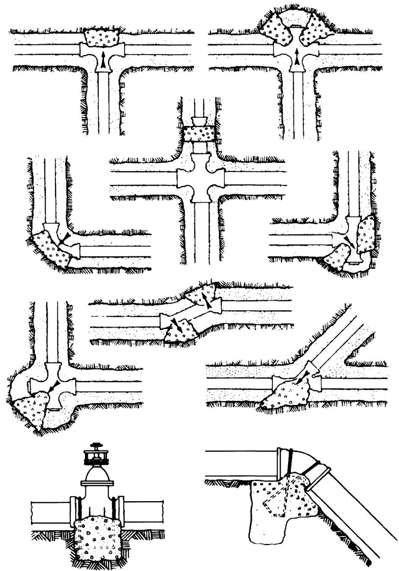
FIGURE 1
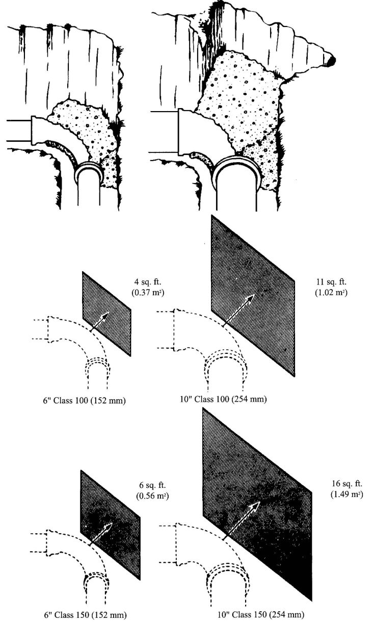
FIGURE 2
1.0 SCOPE.
1.1 This installation standard shall apply to PVC building drain, waste, and vent systems as governed by the Uniform Plumbing Code. Material Standard ASTM D 2665, “Standard Specification for Poly (Vinyl Chloride) (PVC) Plastic Drain, Waste and Vent Pipe and Fittings”,shall form part of this installation standard.
1.2 Installation, material and inspection shall comply with the current edition of the Uniform Plumbing Code [UPC]TM published by the International Association of Plumbing and Mechanical Officials and shall also comply with this standard.
Note: The Building Official shall be consulted about penetration of fire separations, height and area, or other limitations.
Note: The following sections of the Uniform Plumbing Code apply.
| 101.4.1.1 | Repair and Alterations |
| 103.5 | Inspections |
| 103.5.3 | Testing of Systems |
| 218.0 | Definition PVC |
| 301.1 | Minimum Standards |
| 311.8 | Screwed Fittings |
| 310.0 | Workmanship |
| 311.0 | Prohibited Fittings and Practices |
| 313.0 | Protection of Piping, Materials, and Structures |
| 314.0 | Hangers and Supports |
| 316.1.6 | Type of Joints–Solvent Cement Plastic Pipe Joints |
| 316.2 | Special Joints |
| 316.3 | Flanged Fixture Connections |
| 316.4 | Prohibited Joints and Connections |
| 317.0 | Increasers and Reducers |
| 408.4 | Closet Flanges |
| 701.0 | Materials (Drainage) |
| 707.1 | Cleanout Fittings |
| 903.0 | Materials (Venting) |
| 903.3 | Straining or Bending Pipe |
| 1003.0 | Traps Described |
| 1101.3 | Materials Uses |
| Table 14-1 Pipe and Fittings | |
| ASTM D 2665 | ASTM D 2122 |
| ASTM D 3311 |
| ABBREVIATIONS | |
|---|---|
| ASTM | American Society for Testing and Materials |
| IAPMO | International Association of Plumbing and Mechanical Officials |
| UPC | Uniform Plumbing Code |
2.0 PRODUCT REQUIREMENTS
2.1 Minimum Standards.
2.1.1 Pipe. PVC pipe markings shall be in accordance with ASTM D 2665. [UPC 301.1.2]
2.1.2 Fittings. PVC fitting markings shall be in accordance with ASTM D 2665 or ASTM D 3311. [UPC 301.1.2]
2.1.3 Solvent Cement. Solvent cement lable markings shall be in accordance with ASTM D 2564.
2.1.3.1 Solvent cements shall not be purple in color.
2.1.4 Primers. Primer container markings shall be in accordance with ASTM F 656.
2.1.4.1 Primer shall be purple.
2.2 Workmanship.
2.2.1 Alignment.
All piping systems components shall be aligned properly without strain. Pipe shall not be bent or pulled into position. Vertical piping shall be maintained in straight alignment between floors with midstory guides.
Pipe and fittings shall be so positioned that identifying markings shall be readily visible for inspection. [UPC 310.0]
2.3 Protection of Piping.
2.3.1 Storage.
Pipe and fittings should not be stored in direct sunlight; however, exposure to sunlight during normal construction periods is not considered harmful. Pipe shall be stored in such a manner as to prevent sagging or bending.
1Although referenced in this standard, some of the fittings shown in the standards are not acceptable under the Uniform Plumbing Code.
2It is common practice to dual mark Schedule 40 DWV and potable water piping in which compliance with each applicable standard is met.
2.3.2 Expansion and Contraction.
Thermal expansion and contraction of plastic drain waste and vent systems shall be taken into consideration. Thermal expansion and contraction may be controlled by several methods: offset, expansion joints, or restraints.
Regardless of method utilized, certain conditions shall be met:
DWV installation with frequent changes in direction will compensate for thermal expansion and contraction.
Expansion joints may be utilized in vertical straight runs in excess of 30 feet (9,144 mm) provided they are installed per manufacturer's installation instructions.
Except piping buried below ground, horizontal and vertical piping should be installed with restraint fittings or a minimum of 24 inches (610 mm) 45° offset every 30 feet (9,144 mm). Thermal expansion for installation subject to temperature changes may be determined from Table 3-1. The linear expansion shown is independent of the diameter of the pipe. [UPC 313.0]
2.3.3 Exposed Piping.
Piping shall not be exposed to direct sunlight.
Exception: Vent piping through roof. Plumbing vents through roof, exposed to sunlight, shall be protected by water base synthetic latex paints.
Adequate support shall be provided where PVC piping is exposed to wind, snow, and ice loading.
2.3.4 Protection from Damage.
Piping passing through wood studs or plates shall be protected from puncture by minimum 1/16 inch (1.6 mm) thick steel plate.
Piping shall be protected from concrete from oil. [UPC 313.9]
2.3.5 Anti-Freeze Protection.
PVC pipe and traps can be protected from freezing by the use of one of the following solutions of mixtures:
The salt solutions are effective to approximately 10°F (-12°C). If lower temperatures are anticipated, the pipe should be drained or the glycerol solution should be used. [UPC 313.6]
2.4 Piping Installed in Fire Resistive Construction.
Where piping is installed and penetrates required fire resistive construction, the fire resistive integrity of the construction shall be as required by the Administrative Authority, or when not established by the Building Code, by qualified testing methods approved by the Administrative Authority. Approval shall be obtained prior to installing any such piping. [UPC 313.7]
2.5.0 Hangers and Supports.
2.5.1 Abrasion.
Hangers and straps shall not compress, distort, cut, or abrade the piping and shall allow free movement of pipe. Pipe, exposed to damage by sharp surfaces, shall be protected. [UPC 314.0]
2.5.2 Support.
Support all horizontal piping at intervals of not more than four (4) feet (1,219 mm), at end of branches, and at change of direction or elevation. Supports shall allow free movement, but shall restrict upward movement of lateral runs so as not to create reverse grade. Vertical piping shall be supported at each story or floor level. Alignment of vertical piping shall be maintained between floors with the use of a mid-story guide. Support trap arms in excess of three (3) feet (915 mm) in length as close as possible to the trap. Closet flanges shall be securely fastened with corrosive resistant fasteners to the floor with top surface one-quarter (¼) inch (6.4 mm) above finish floor. [UPC314.0]
2.6 Traps.
2.6.1 Connection to Traps.
Traps shall be connected by means of listed trap adapters. [UPC 1003.0]
2.7 Joints.
2.7.1 Caulked Joints.
Make connections or transitions to bell-and-spigot cast iron soil pipe fittings, and to bell-and-spigot pipe and fittings of other materials with listed mechanical compression joints designed for this use, or caulked joints made in an approved manner. In caulking, pack the joint with oakum or hemp and fill with molten lead to a depth of not less than one (1) inch (25.4 mm). Allow a period of four (4) minutes for cooling, following which, caulk the lead at the inside and outside edges of the joint. Lead shall not be overheated. [UPC 705.1.1]
2.7.2 Solvent Cement Joints.
(Additional information is available in ASTM D 2855.)
| LENGTH (feet) | 40°F | 50°F | 60°F | 70°F | 80°F | 90°F | 100°F |
|---|---|---|---|---|---|---|---|
| 20 | 0.278 | 0.348 | 0.418 | 0.487 | 0.557 | 0.626 | 0.696 |
| 40 | 0.557 | 0.696 | 0.835 | 0.974 | 1.114 | 1.235 | 1.392 |
| 60 | 0.835 | 1.044 | 1.253 | 1.462 | 1.670 | 1.879 | 2.088 |
| 80 | 1.134 | 1.392 | 1.670 | 1.949 | 2.227 | 2.506 | 2.784 |
| 100 | 1.392 | 1.740 | 2.088 | 2.436 | 2.784 | 3.132 | 3.480 |
| LENGTH (mm) | 4°C | 10°C | 16°C | 21°C | 27°C | 32°C | 38°C |
|---|---|---|---|---|---|---|---|
| 6096 | 7.1 | 8.8 | 10.6 | 12.4 | 14.2 | 15.9 | 17.7 |
| 12192 | 14.2 | 17.7 | 21.2 | 24.7 | 28.3 | 31.4 | 35.4 |
| 18288 | 21.2 | 26.5 | 31.8 | 37.1 | 42.4 | 47.7 | 53.0 |
| 24384 | 28.8 | 35.4 | 42.4 | 49.5 | 56.6 | 63.7 | 70.7 |
| 30480 | 35.4 | 44.2 | 53.0 | 61.9 | 70.7 | 79.6 | 88.4 |
| Example: | ||
| Highest Temperature expected | 100°F | (38°C) |
| Lowest Temperature expected | 50°F | (10°C) |
| 50°F | (10°C) | |
| Length of run - 60 feet (18,288 mm) from chart, read 1.044 inches (26.5 mm) linear expansion that must be provided for. | ||
2.7.3 Selection. Follow manufacturer's recommendations for type of solvent cement for such conditions as temperature over 100°F (38°C), or humidity over 60%.
2.7.4 Handling (to maintain effectiveness). Solvent cement and primer containers no larger than I quart (1 liter) should be used in the field (to avoid thickening due to evaporation). Keep containers closed and in the shade when not in use. Keep applicator submerged in solvent cement between applications. When solvent cement becomes thicker, THROW IT AWAY. Solvent cement shall NOT be thinned.
2.7.5 Size of Applicator. Applicator should be about one-half the pipe diameter. Do not use small applicator on large pipes. Ordinary pure bristle paint brushes or applicators furnished with product are satisfactory. [UPC 316.1.6]
2.7.6 Primers. A listed primer in compliance with ASTM F 656 shall be used on all PVC DWV joints.
2.7.7 Application. Solvent cement and primer shall be applied deliberately, but without delay (two men may be needed to make large joints). Use special care when temperature is over 100°F (38°C) or humidity is over 60%.
2.7.8 SAFETY REQUIREMENTS AND PRECAUTIONS.
2.7.8.1 General. Solvents contained in PVC plastic pipe cements are classified as airborne contaminants and flammable and combustible liquids. Precautions listed in this appendix should be followed to avoid injury to personnel and the hazard of fire.
2.7.8.2 Safety Precautions. Prolonged breathing of solvent vapors should be avoided. When pipe and fittings are being joined in partially enclosed areas, a ventilating device should be used in such a manner to minimize the entry of vapors into the breathing areas.
2.7.8.3 Solvent cements should be kept away from all sources of ignition, heat, sparks and open flame.
2.7.8.4 Containers for solvent cements should be kept tightly closed except when the cement is being used.
2.7.8.5 All rags and other materials used for mopping up spills should be kept in a safety waste receptacle which should be emptied daily.
2.7.8.6 Most of the solvents used in PVC pipe cements can be considered eye irritants and contact with the eye should be avoided for it may cause eye injury. Proper eye protection and the use of chemical goggles or face shields is advisable where the
possibility of splashing exists in handling solvent cements. In case of eye contact, flush with plenty of water for 15 minutes and call a physician immediately.
2.7.8.7 Repeated contact with the skin should be avoided. Proper gloves impervious to and unaffected by the solvents should be worn when frequent contact with the skin is likely. Application of the solvents or solvent cements with rags and bare hand is not recommended. Brushes and other suitable applicators can be used effectively for applying the solvent cement, thus avoiding skin contact. In the event of excessive contact, remove contaminated clothing and wash skin with soap and water.
Step 1 Cut pipe square with hand saw and miter box, mechanical cut-off saw or tube cutter designed for plastic.
Step 2 Ream inside and chamfer outside of pipe (to eliminate all burrs).
Step 3 Clean all dirt, moisture, and grease from pipe and socket. Use a clean, dry rag.
Step 4 Check dry fit of pipe in fitting. Pipe should enter fitting socket from 1/3 to ¾ depth of socket.
Step 5 Soften inside socket surface by applying an aggressive primer.
Step 6 Soften mating outside surface of pipe to depth of socket by applying a liberal coat of the (aggressive) primer. Be sure the entire surface is softened.
Step 7 Again coat inside socket surface with the (aggressive) primer. Then, without delay, apply solvent cement liberally to outside of pipe. Use more than enough to fill any gaps.
Step 8 Apply a light coat of PVC solvent cement to inside of socket using straight outward strokes (to keep excess solvent out of socket). This is also to prevent solvent cement damage to pipe. For loose fits, apply a second coat of solvent cement. Time is important at this stage. See Section 2.7.6.
Step 9 While both the inside socket surface and the outside surface of the pipe are SOFT and WET with solvent cement, forcefully bottom the pipe in the socket, giving the pipe a one-quarter turn, if possible. The pipe must go to the bottom of the socket.
Step 10 Hold the joint together until tight. (Partial set).
Step 11 Wipe excess cement from the pipe. A properly made joint will normally show a bead around its entire perimeter. Any gaps may indicate insufficient cement or the use of light bodied cement on larger diameters where heavy bodied cement should have been used.
Step 12 The system shall not be tested until the joints have cured (set) at least as long as recommended by the manufacturer.
2.7.9 Threaded Joints.
Listed adapter fittings shall be used for the transition to threaded connections. No threaded PVC female fitting(s) or joint(s) shall be located in a non-accessible location. The joint between the PVC pipe and adapter fittings shall be of the solvent cement type.
Only listed thread tape or thread lubricant, specifically intended for use with plastics, shall be used. Conventional pipe thread compounds, putty, linseed oil base products, and unknown mixtures shall not be used. Pipe and fittings which have come in contact with the above non-approved mixtures shall be removed and replaced with new materials.
Where a threaded joint is made, obtain tightness by maximum hand tightening plus additional tightening with a strapwrench not to exceed one full turn.
2.7.10 Special Joints.
2.7.10.1 Connection to Non-Plastic Pipe.
When connecting plastic pipe to other types of piping, use listed fittings and adapters designed for the specific use intended. [UPC 316.2]
2.7.11 Prohibited Joints and Connections.
ADOPTED: 1968
REVISED: 1971, 1974, 1975, 1976, 1977, 1981, 1982, 1983, 1987, 1989, 1990, 1991, 1992, 1995, 2003, 2006
1.0 SCOPE.
1.1 This Installation Standard shall apply to ABS Building Sewer Pipe and Fittings as governed by the Uniform Plumbing Code. Material Standard ASTM D 2751, Standard Specification for Acrylonitrile-Butadiene-Styrene (ABS) Sewer Pipe and Fittings shall form part of this Installation Standard. Materials shall be limited to building sewers receiving domestic sewage excluding special and industrial waste.
Note: The following sections of the Uniform Plumbing Code apply.
| 1 Although this standard is referenced in Table 14-1, some of the tube or fittings shown in the standard are not acceptable for use under the Uniform Plumbing Code. | |
| 101.4.1.1 | Repairs and Alterations |
| 103.5 | Inspection and Testing |
| 203.0 | Definition ABS |
| 206.0 | Domestic Sewage |
| 301.1 | Minimum Standards |
| 310.0 | Workmanship |
| 312.0 | Independent Systems |
| 313.3 and 313.4 | Protection of Piping, Materials, and Structures |
| 314.0 | Hangers and Supports |
| 315.0 | Trenching, Excavation, and Backfill |
| 316.1 | Types of Joint |
| 317.0 | Increasers/Reducers |
| 705.1.1 | Caulked Joints |
| 705.1.7 | Elastomeric Gasketed and RubberRing Joints |
| 713.0 | Sewer Required |
| 715.0 | Building Sewer Materials |
| 718.0 | Grade, Support, and Protection of Building Sewers |
| 719.0 | Cleanouts |
| 720.0 | Sewer and Water Pipes |
| 723.0 | Building Sewer Test |
| Table 14-1 | ASTM D27511 |
2.0 PRODUCT REQUIREMENTS.
2.1 Minimum Standards.
2.1.1 Pipe. ABS pipe is furnished in straight lengths. Refer to Tables in ASTM D 2751 for dimensions and tolerances for pipe and pipe sockets.
ABS pipe markings shall be in accordance with ASTM D 2751. [UPC 301.1.2]
2.1.2 Fittings. Refer to Tables in ASTM D 2751 for dimensions and tolerances for fitting sockets, spigots, and laying lengths.
ABS fitting markings shall be in accordance with ASTM D 2751. [UPC 301.1.2]
2.1.3 Solvent Cement. Solvent cement shall be as specified in ASTM D 2235.
Solvent cement label markings shall be in accordance with ASTM D 2235. [UPC 316.1.6]
2.2 Workmanship.
All piping system components shall be aligned properly without strain. Pipe shall not be bent or pulled into position after being solvent cemented. Pipe and fittings shall be so positioned that identifying markings shall be readily visible for inspection. [UPC 310.0]
2.3 Protection of Piping.
2.3.1 Storage.
Pipe and fittings should not be stored for long periods in direct sunlight. However, exposure to direct sunlight during normal construction periods is not harmful. Pipe shall be stored in such a manner as to prevent sagging or bending.
2.4 Trenching, Excavation, and Backfill.
2.4.1 Trenching.
The width of the trench at any point below the top of the pipe should not be greater than necessary to provide adequate room for joining the pipe and compacting the side fills. [UPC 315.0]
2.5 Alignment and Grade.
The pipe should be bedded true to line and grade, uniformly and continuously supported on firm, stable material. Blocking shall not be used to bring the pipe to grade. The bedding shall conform to Section 718.0 of the Uniform Plumbing Code.
2.6 Backfill.
The backfill shall conform to Section 315.4 of the Uniform Plumbing Code.
2.7 Joints.
2.7.1 Caulked Joints.
Make connections or transitions to bell-and-spigot cast iron soil pipe and fittings, and to bell-and-spigot pipe and fittings of other materials with approved mechanical compression joints designed for this use, or caulked joints made in an approved manner. In caulking, pack the joint with oakum or hemp and fill with molten lead to a depth of not less than one (1) inch (25.4 mm). Allow a period of four (4) minutes for cooling, following which, caulk the lead at the inside and outside edges of the joint. Lead shall not be overheated. [UPC 705.1.1]
Note: Caulked joints should be avoided if possible.
2.7.2 Gasket-Type Joints.
Pipe shall be cut square with saws or pipe cutters designed specifically for plastic pipe; protect pipe and fittings from serrated holding devices and abrasion. [UPC 705.1.7]
2.7.3 Solvent Cement Joints.
2.7.3.1 Selection. Solvent cement shall be recommended for ABS by the manufacturer. Follow manufacturer's recommendations for types of solvent cement for such conditions as temperature over 100°F (38°C), or humidity over 60%.
2.7.3.2 Handling (to maintain effectiveness). Solvent cement containers no larger than 1 quart (1 liter) should be used in the field (to avoid thickening due to evaporation). Keep container closed and in the shade when not in use. Keep applicator submerged in solvent cement between applications. When solvent cement becomes thicker, THROW IT AWAY. Solvent cement shall NOT be thinned.
2.7.3.3 Size of Applicator. Applicator should be about one half the pipe diameter. Do not use small applicator on large pipes. Ordinary pure bristle paint brush or applicators furnished with product are satisfactory.
2.7.3.4 Application. Solvent cement shall be applied deliberately, but without delay (two men may be needed to make large joints). Use special care when temperature is over 100°F (38°C) or humidity is over 60%.
2.7.4 SAFETY REQUIREMENTS AND PRECAUTIONS.
2.7.4.1 General. Solvents contained in ABS plastic pipe cements are classified as airborne contaminants and flammable and combustible liquids. Precautions listed in this appendix should be followed to avoid injury to personnel and the hazard of fire.
2.7.4.2 Safety Precautions. Prolonged breathing of solvent vapors should be avoided. When pipe and fittings are being joined in partially enclosed areas, a ventilating device should be used in such a manner to minimize the entry of vapors into the breathing areas.
2.7.4.3 Solvent cements should be kept away from all sources of ignition, heat, sparks, and open flame.
2.7.4.4 Containers for solvent cements should be kept tightly closed except when the cement is being used.
2.7.4.5 All rags and other materials used for mopping up spills should be kept in a safety waste receptacle which should be emptied daily.
2.7.4.6 Most of the solvents used in ABS pipe cements can be considered eye irritants and contact with the eye should be avoided for it may cause eye injury. Proper eye protection and the use of chemical goggles or face shields is advisable where the possibility of splashing exists in handling solvent cements. In case of eye contact, flush with plenty of water for 15 minutes and call a physician immediately.
2.7.4.7 Repeated contact with the skin should be avoided. Proper gloves impervious to and unaffected by the solvents should be worn when frequent contact with the skin is likely. Application of the solvents or solvent cements with rags and bare hand is not recommended. Brushes and other suitable applicators can be used effectively for applying the solvent cement, thus avoiding skin contact. In the event of excessive contact, remove contaminated clothing and wash skin with soap and water.
Step 1 Cut pipe square with hand saw and miter box, mechanical cut-off saw, or tube cutter designed for plastic.
Step 2 Ream inside and chamfer outside of pipe (to eliminate all burrs).
Step 3 Clean all dirt, moisture, and grease from pipe and socket. Use a clean, dry rag.
Step 4 Check dry fit of pipe in fitting. Pipe should enter fitting socket from 1/3 to ¾ depth of socket.
Step 5 Apply a light coat of ABS solvent cement to inside of socket using straight
outward strokes (to keep excess solvent out of socket). This is also to prevent solvent cement damage to pipe. For loose fits, apply a second coat of solvent cement. Time is important at this stage. See Section 2.7.3.4.
Step 6 While both the inside socket surface and the outside surface of the pipe are SOFT and WET with solvent cement, forcefully bottom the pipe in the socket, giving the pipe a one-quarter turn, if possible. The pipe must go to the bottom of the socket.
Step 7 Hold the joint together until tight (partial set).
Step 8 Wipe excess cement from the pipe. A properly made joint will normally show a bead around its entire perimeter. Any gaps may indicate insufficient cement or the use of light bodied cement on larger diameters where heavy bodied cement should have been used.
Step 9 The system shall not be tested until the joints have cured (set) at least as long as recommended by the manufacturer.
2.7.5 Special Joints.
2.7.5.1 Connection to Non-Plastic Pipe.
When connecting plastic pipe to other types piping, use only approved types of fittings and adapters, designed for the specific transition intended.
ADOPTED: 1976
REVISED: 1981, 1987, 2003, 2006
1.0 SCOPE.
1.1 This standard shall govern the installation of polyethylene (PE) natural and liquified petroleum gas yard piping. Installation, material and inspection shall comply with the current edition of the Uniform Plumbing Code [UPC]TMpublished by the International Association of Plumbing and Mechanical Officials and shall also comply with this standard.
Note: The following sections of the Uniform Plumbing Code apply to PE gas piping:
| 218.0 | Definition of PE |
| 310.0 | Workmanship |
| 313.0 | Protection of Piping, Materials, and Structures |
| 314.0 | Hangers and Supports |
| 315.0 | Trenching, Excavation, and Backfill |
| 316.2.3 | Plastic Pipe to Other Materials |
| Chapter 12 | Fuel Piping |
| 1204.3.2 | Final Piping Inspection |
| 1211.0 | Gas Piping Installation |
| 1211.1.7 | Tracer Wire |
| 1213.0 | Liquified Petroleum Gas Facilities and Piping |
| Table 14-1 | Materials: |
| Pipe and Tube: | ||
| PE3408 | ASTM D 2513 | |
| PE2406 | ||
| Fittings: | ||
| Copper Alloy | ANSI B 16.26 | |
| PE3408 | ASTM D 2513 | |
| PE2406 | ||
| Plastic Mechanical | ||
| ASTM F 1924 | ||
| Metallic Mechanical | ||
| ASTM F 1948 |
ABBREVIATIONS
| ANSI | American National Standards Institute |
| ASTM | American Society for Testing and Materials |
| IAPMO | International Association of Plumbing and Mechanical Officials |
| UPC | Uniform Plumbing Code published by IAPMO |
2.0 PRODUCT REQUIREMENTS
2.1 Minimum Standards.
2.1.1 Materials. Pipe, tubing and fittings shall conform to the appropriate standards in Table 14-1 of the Uniform Plumbing Code. See note ahead of Chapter 2 of this standard. [UPC 301.1]
2.1.2 Pipe. PE pipe is plastic of ½ inch (12.7 mm) or larger size. One-half inch (12.7 mm) pipe shall be SDR 9. Pipe sizes less than 3 inches (76 mm) shall be SDR 11. Pipes 3 inches (76 mm) and larger shall be SDR 11.5 or lower*.
2.1.3 Tubing. PE tubing is plastic and shall be limited to the following:
| TUBING SIZE | ||
|---|---|---|
| inches | (mm) | SDR* |
| *Note: The lower the SDR number, the thicker the wall. | ||
| ¼ | (6.4) | 6 |
| 3/8 | (9.5) | 8 |
| ½ | (12.7) | 7 |
2.1.4 Fittings. Heat fusion fittings shall be PE 2406, PE 3408, or other listed materials. Mechanical connectors for PE pipe and tubing and for transition fittings shall be approved compression type couplings or other special listed joints.
2.2 Markings.
2.2.1 Pipe and Tubing. Pipe and tubing markings shall be in accordance with ASTM D 2513. [UPC 301.1.2]
2.2.2 Fittings. Fitting markings shall be in accordance with ASTM D 1924, ASTM D 1948, ASTM D 2513, or ASME B 16.26. [UPC 301.1.2]
2.2.3 Position of Markings. The identifying markings on pipe, tubing and fittings shall be visible for inspection without moving materials.
2.3 Protection of Piping.
2.3.1 Storage. Unprotected pipe should not be stored in direct sunlight. The pipe shall be stored in a way to protect it from mechanical damage (slitting, puncturing, etc.). Exposure to sunlight during normal construction periods is not harmful.
2.4 Thermal Expansion.
2.4.1 Snaking. The pipe and tubing shall be “snaked” in the trench bottom with enough slack to provide for thermal expansion and contraction before stabilizing. The normal slack created by residual coiling is generally sufficient for this purpose. If, however, the pipe has been allowed to straighten before it is placed in the trench, 6 inches (152 mm) per 100 feet (30,480 mm) of pipe length shall be allowed for this purpose.
2.4.2 Stabilizing. Pipe and tubing temperature shall be stabilized by one of the following methods:
2.5 Trenching and Backfill.
2.5.1 Trenching. Trenching bottoms shall be smooth and regular of either undisturbed soil or a layer of compacted backfill so that minimum settlement will take place. Pipe or tubing shall not be wedged or blocked. Voids shall be filled and compacted to level of trench bottom. The minimum cover shall be 18 inches (457 mm) below finish grade. [UPC 315.0, 1211.1.2]
Exceptions:
Note: Local climatic conditions may affect required burial depth.
2.5.2 Backfill. The pipe and tubing temperature shall be stabilized before backfilling. See Section 2.4.2. [UPC 315.4, 1211.1.2]
2.6 Types of Joints.
PE joints shall be made as follows:
2.6.1 Heat Fusion Joints. Heat fusion joints shall be made according to the manufacturer's procedures using recommended heat times, temperature and joining pressures. [UPC 1209.5.9]
2.6.2 Mechanical Joints. Mechanical joints shall be assembled in an approved manner with tools recommended by the fitting manufacturer. Mechanical joints shall be made with listed mechanical fittings. [UPC 1209.5.9]
2.7 Special Joints.
2.7.1 Listed transition fittings or listed mechanical fittings shall be used when making joints between PE and steel or PE and copper.
2.7.2 Transition fittings shall be installed outside of meter vaults with metallic piping extending into the vaults a sufficient distance to permit the use of backup wrenches.
2.8 Inspections.
2.8.1 Temperature. Pipe temperatures shall be stabilized before testing. See Section 2.4.2 [UPC 1214.0]
2.8.2 Piping shall be subjected to the pressure test required in Section 1214.0 of the Uniform Plumbing Code. [UPC 1214.0]
2.9 Materials.
2.9.1 Location. PE pipe and tubing shall be installed only outside the foundation of any building or structure or parts thereof. It shall be buried in the ground for its entire length with cover as provided in Section 2.5.1. It shall not be installed within or under any building or structure or mobile home or commercial coach or parts thereof. The term “building or structure or parts thereof" shall include structures such as porches and steps, whether covered or uncovered, roofed portecocheres, roofed patios, carports, covered walks, covered driveways and similar structures or appurtenances. [UPC 1211.0]
Exception:Tubing may extend into gas light support columns provided it is not exposed to external damage.
2.9.2 Maximum Working Pressure. Gas pressure shall not be more than 5 psi (34.5 kPa) for natural gas nor more than 10 psi (69 kPa) for liquified petroleum gas.
2.9.3 Gas Supplier. Installation shall be acceptable to the serving gas supplier.
2.10 Installation of Gas Piping.
2.10.1 Types of Joints. See Sections 2.6 and 2.7 of this standard. [UPC 1209.5.9]
2.10.2 Prohibited Joints. PE pipe shall not be joined by a threaded joints. Joints made with adhesives or solvent cement shall be prohibited.
2.10.3 Identification. Plastic gas yard piping shall be permanently identified by attaching a metal tag to the meter end of the piping system stating, “Plastic Yard Piping”.
2.11 Sizing.
2.11.1 Pipe. Pipe shall be sized as required by Section 1211.16 or 1217.0 of the UPC. [UPC 1211.16, 1217.0]
2.11.2 Tubing. Tubing shall be sized from Table 1. [UPC 1217.0]
ADOPTED: 1971
REVISED: 1975, 1977, 1978, 1981, 1983, 1985, 1989, 1990, 1991, 1993, 2003, 2006
| NOMINAL TUBING SIZE (inches) | INTERNAL DIAMETER (inches) | LENGTH IN FEET | ||||||||||
|---|---|---|---|---|---|---|---|---|---|---|---|---|
| 10 | 20 | 30 | 40 | 50 | 60 | 70 | 80 | 90 | 100 | 125 | ||
| ¼ | 0.250 | 18 | 12 | 10 | 8 | 7 | 7 | 6 | 6 | 5 | 5 | 4 |
| 3/8 | 0.375 | 51 | 35 | 28 | 24 | 21 | 19 | 18 | 16 | 16 | 15 | 13 |
| 150 | 200 | 250 | 300 | 350 | 400 | 450 | 500 | 550 | 600 | |||
| ¼ | 0.250 | 4 | 3 | 3 | 3 | 3 | 2 | 2 | 2 | 2 | 2 | |
| 3/8 | 0.375 | 12 | 10 | 9 | 8 | 7 | 7 | 6 | 6 | 6 | 6 | |
| NOMINAL TUBING SIZE (mm) | INTERNAL DIAMETER (mm) | LENGTH IN METERS | ||||||||||
|---|---|---|---|---|---|---|---|---|---|---|---|---|
| 3.0 | 6.1 | 9.1 | 12.2 | 15.2 | 18.3 | 21.3 | ||||||
| 6.4 | 6.4 | 1.4 | 1.0 | 0.8 | 0.6 | 0.56 | 0.56 | 0.5 | ||||
| 9.5 | 9.5 | 4.1 | 2.8 | 2.2 | 1.9 | 1.7 | 1.5 | 1.4 | ||||
| 24.4 | 27.4 | 30.5 | 38.1 | 45.7 | 61.0 | 76.2 | ||||||
| 6.4 | 6.4 | 0.5 | 0.4 | 0.4 | 0.3 | 0.3 | 0.2 | 0.2 | ||||
| 9.5 | 9.5 | 1.3 | 1.2 | 1.2 | 1.0 | 0.96 | 0.8 | 0.7 | ||||
| 91.4 | 106.7 | 121.9 | 137.2 | 152.4 | 167.6 | 182.9 | ||||||
| 6.4 | 6.4 | 0.2 | 0.2 | 0.16 | 0.16 | 0.16 | 0.16 | 0.16 | ||||
| 9.5 | 9.5 | 0.6 | 0.56 | 0.56 | 0.5 | 0.5 | 0.5 | 0.5 | ||||
1.0 SCOPE.
1.1 Installation and material of protective pipe coatings shall comply with this Standard and the current edition of the Uniform Plumbing Code [UPC]TM, published by the International Association of Plumbing and Mechanical Officials (IAPMO).
Note: The following sections of the Uniform Plumbing Code shall apply to protectively coated pipe.
| 301.1.2 | Marking | |
| 302.0 | Iron pipe size (IPS) pipe | |
| 310.0 | Workmanship | |
| 311.0 | Prohibited fittings and practices | |
| 313.5 | Protection required | |
| 314.0 | Hangers and supports | |
| 604.0 | Materials – water piping | |
| 609.3.1 | Coated protection required | |
| 1209.5 | Materials – gas piping | |
| 1209.5.6 | Coated protection required and coating material approval required |
2.0 PRODUCT REQUIREMENTS.
2.1 Minimum Standards.
2.1.1 Materials.
2.1.1.1 Coating. Piping shall be coated by a listed coating applicator in accordance with AWWA C203, AWWA C213, or AWWA C215.
2.1.1.2 Tape. Tape for field application shall comply with IAPMO PS 37, Black Plastic PVC or PE Pressure-Sensitive Corrosion Preventive Tape.
2.1.1.3 Primer. Primer for field application shall be compatible with the tape and be as recommended by the tape manufacturer.
2.1.2 Markings.
2.1.2.1 Pipe. Protectively coated pipe shall be legibly marked at least every two (2) feet (610 mm) as follows:
2.1.2.2 Tape. Tape for field applications should be legibly marked at least every two (2) feet (610 mm) with the manufacturer's name and tape model identification.
2.2 Protection of Piping and Fittings.
2.2.1 Field Joints. Field joints shall be made as follows, except as specified in Section 2.2.2. Clean and dry surfaces to be protected. [UPC 313.0]
Step 1 Oil and grease, if present, shall be removed with suitable non-oily type solvent such as Heptane or Trichlorethylene. Materials, such as kerosene and gasoline, shall not be used.
Step 2 For coated pipe, remove coating approximately 3 inches (76 mm) from end of pipe or from repair area and bevel to expose shoulder of coating at area to be field wrapped.
Step 3 For taped pipe, remove tape and overwrapping so as to expose approximately 3 inches (76 mm) of pipe at area to be field wrapped.
Step 4 For welded pipe, grind down sharp welds and weld spatter to a minimum 1/8 inch (3.2 mm) radius. Wire brush the weld area thoroughly taking care to remove as much mil scale and surface rust as possible. Remove any loose or charred coating caused during welding.
Step 5 Apply listed primer, as recommended by the manufacturer of the tape being applied, over the protected area and adjacent 1 inch (25.4 mm) of protected area.
Step 6 Spirally wrap listed tape by a half overlap double wrap of minimum 10 mil tape stretched around the fitting, thread, and other unprotected areas to provide a minimum 40 mil thickness. A maximum of two (2) inch (51 mm) wide tape shall be used for field application.
Exception: Unless otherwise listed by
IAPMO, a maximum of one (1) inch (25.4 mm) wide tape shall be used on change of direction fittings for piping sizes up to and including two (2) inch (51 mm).
2.2.2 Other Methods. Other materials approved for field joints or repair shall be applied as per manufacturer's recommendations and the listing requirements.
2.3 Damage in Shipment. Coated piping shall be protected against damage in shipment.
2.3.1 Handling and Storage. Coated piping shall be handled and stored in a manner to prevent damage.
2.3.2 Handling by Installer. Movement of pipe from truck or into trench shall be done in such a manner as to avoid abrasion, or damage from dropping.
2.4 Backfill. All excavations shall be completely backfilled as soon after inspection as possible. [UPC 315.0]
2.5 Inspection. All coated piping shall be inspected and tested and any visible void, damage or imperfection to the pipe coating shall be repaired as to comply with Section 2.2.
2.5.1 Equipment. The equipment, material, and labor necessary for inspection or tests shall be furnished by the person to whom the permit is issued or by whom inspection is requested.
ADOPTED: 1971
REVISED: 1975, 1978, 1982, 1984, 1991, 2000, 2003, 2006
1.0 SCOPE.
1.1 This standard shall govern the installation of asbestos cement pressure pipe and fittings with elastomeric gasketed joints in hot and cold water building supply and yard piping. For allowable location and pressure, see Sections 2.4 and 2.5.2 of this standard. Installation, material, and inspection shall comply with the current edition of the Uniform Plumbing Code [UPC]TM published by the International Association of Plumbing and Mechanical Officials, and shall also comply with this standard.
Note: The following sections of the Uniform Plumbing Code apply to asbestos cement pressure piping systems.
| 310.0 | Workmanship |
| 313.0 | Protection of Piping, Materials and Structures |
| 314.0 | Hangers and Supports |
| 315.0 | Trenching, Excavation, and Backfill |
| Chapter 6 | Water Supply and Distribution |
| Table 14-1 | Materials |
| Chapter 2 | DEFINITIONS. | |
| 202.0 | AC | Asbestos Cement |
| Chapter 14 | ASTM | American Society for Testing and Materials |
| IAPMO | International Association of Plumbing and Mechanical Officials | |
| UPC | Uniform Plumbing Code published by IAPMO | |
2.0 PRODUCT REQUIREMENTS.
2.1 Minimum Standards.
2.1.1 Material. Materials shall conform to the appropriate standard in Table 14-1 of the Uniform Plumbing Code.
| Applicable Standards: | |
| AC Pipe | ASTM C296 |
| Fittings | AWWA/ANSI A21.10 |
| Rings | ASTM D1869 |
| Joints | AWWA/ANSI A21.11 |
2.1.2 Pipe. Pipe is asbestos cement.
2.1.3 Fittings. Fittings are cast iron or other listed materials.
2.1.4 Markings.
2.1.4.1 Pipe. Pipe markings shall be in accordance with ASTM C 296. [UPC 301.1.2]
2.1.4.2 Fittings. Fitting markings shall be in accordance with AWWA A21.10. [UPC 301.1.2]
2.1.4.3 Couplings. Couplings shall be marked with at least the following:
2.1.4.4 Position of Markings. The identifying markings on pipe and fittings shall be visible for inspection without moving materials unless otherwise acceptable to the Administrative Authority.
2.2 Trenching, Cover, and Backfill.
2.2.1 Trenching and Cover. Trench bottoms shall be uniformly graded and shall be of either undisturbed soil or shall consist of a layer or layers of compacted backfill so that minimum settlement will take place.
The trench bottoms shall be at least 12 inches (305 mm) below the average local frost depth. The minimum cover shall be 18 inches (458 mm) below the finish grade. [UPC 315.0]
2.2.2 Backfill. After finishing pressure testing of the line, backfill a minimum of twelve (12) inches (305 mm) deep over the top of the pipe and fittings. Backfill should be select material placed around the pipe in a manner to provide a firm continuous support. Tamp well to secure proper compaction.
Note: All joints shall be exposed during test.
2.3 Joints.
2.3.1 Joints in asbestos cement pipe shall be a sleeve coupling of the same composition as the pipe, or of other listed materials, and sealed with rubber rings or joined by other listed compression type coupling. [UPC 705.1.4]
2.3.2 Joints between asbestos cement pipe and other approved pipes shall be made by means of listed adapter couplings. Special heat resistant rings as recommended by the manufacturer must be used for temperatures in excess of 140°F (60°C).
2.3.3 Before assembling the joint, the coupling grooves, pipe ends, and rubber gasket must be cleaned. The rubber gaskets are then positioned in the grooves.
2.3.4 Use the pipe manufacturer's joint lubricant recommended for potable water application. Apply lubricant to the machined end of the pipe only, never to the rubber gasket or groove, unless specifically recommended otherwise by the manufacturer.
2.3.5 The end of the pipe and the coupling or fitting bell shall be assembled using a bar and wood block or a pipe puller. "Stabbing" or "popping" the pipe into the coupling (pipe is suspended and swung into the bell) is not recommended.
2.3.6 When a field cut is made, cut the pipe square, using hand pipe-cutters which use a cutting edge, or hand saws. To properly enter the rubber gasketed joint, the end of the pipe must be machined before insertion, using hand machining tools.
2.4 Materials.
2.4.1 Location. Asbestos cement piping shall be installed only outside the foundation of any building or structure or parts thereof. It shall be buried in the ground for its entire length except vertical piping may be extended above grade per Section 313.0 of the Uniform Plumbing Code. It shall not be installed within or under any building or structure or mobile home or commercial coach or parts thereof. The term "building or structure or parts thereof" shall include structures such as porches and steps, roofed porte-cocheres, roofed patios, carports, covered walks, covered driveways, and similar structures or appurtenances. [UPC 604.1]
2.5 Installation, Testing, and Identification.
2.5.1 Alignment and Deflection. Pipe and fittings shall be aligned properly without strain. Pipe may be deflected in accordance with the manufacturer's recommendations provided that it shall not be permanently staked or blocked to maintain this deflection. If soft soil conditions exist, deflected joints may be permanently blocked or staked to maintain the deflection. The amount of deflection shall be: 5° for sizes 4 inch (101.6 mm) through 12 inch (305 mm); 4° for 14 inch (356 mm) and 16 inch (407 mm); 3½degree for 18 inch (457 mm) through 24 inch (610 mm) for pipe belled on the job site. For factory-belled couplings, one half (½) the above deflections by size shall be allowed.
2.5.2 Working Pressure. Maximum working pressure shall be as follows:
| PIPE | SIZES | MAXIMUM PRESSURE |
|---|---|---|
| Class 100 | 4 – 24 inch incl. (102 – 610 mm incl.) | 100 psi (689 kPa) |
| Class 150 | 4 – 24 inch incl. (102 – 610 mm incl.) | 150 psi (1,033 kPa) |
| Class 200 | 4 – 24 inch incl. (102 – 610 mm incl.) | 200 psi (1,378 kPa) |
2.5.3 Laterals and Saddles. Installation of laterals, saddles, or tapped couplings in AC piping shall be as required by their listings.
2.5.4 Thrust Blocking. Thrust blocks shall be installed at:
The size and type of thrust block shall be based on the pressure rating of the pipe (or line test pressure, if greater than piping rating), pipe size and kind of soil 2.5.4(b). Refer to Table 1 for thrust at fittings for a pressure of one hundred (100) pounds per square inch (689 kPa).
2.5.5 To determine the bearing area of thrust blocks, refer to Table 2 for the safe bearing load of the soil and divide the total thrust by this safe bearing load.
2.5.6 Thrust blocks shall be located as shown on Chart 1.
2.5.7 Testing
2.5.7.1 The portion of the line being tested should be complete with thrust blocks or properly sized temporary thrust blocking. The line may be pressure tested immediately after installation, provided however, that if poured concrete thrust blocks have been utilized, they have had a 24-hour period to attain an initial cure. [UPC 609.4]
2.5.7.2 The entire system shall be filled with water, purged of air, and tested at a pressure at least equal to the eventual operating pressure for at least one (1) hour before inspection and backfilling of trench. It is recommended that the test pressure not exceed the working pressure of the pipe.
CAUTION: AIR TESTING IS PROHIBITED.
2.5.7.3 Identification. A label shall be fastened to the main electrical meter panel stating, "This structure has a non-metallic water service."
2.6 Sizing. Piping shall be sized in accordance with UPC Section 610.0. When UPC Appendix A is applicable, Chart A-5 (Fairly Smooth Pipe) may be used. Flow velocities shall be limited to a maximum of 8 fps (2.4 m/s). When using UPC, Table 6-5, required by UPC Section 610.0, velocities shall also be checked and limited using UPC Chart A-5. [UPC 610.0]
| PIPE SIZE | CLASS | DEAD ENDS AND TEES | 90° BEND | 45° BEND | 22 ½° BEND |
|---|---|---|---|---|---|
| 4″ | 100 | 1,720 | 2,440 | 1,320 | 660 |
| 150 | 1,850 | 2,610 | 1,420 | 720 | |
| 200 | 1,850 | 2,610 | 1,420 | 720 | |
| 6″ | 100 | 3,800 | 5,370 | 2,910 | 1,470 |
| 150 | 3,800 | 5,370 | 2,910 | 1,470 | |
| 200 | 3,800 | 5,370 | 2,910 | 1,470 | |
| 8″ | 100 | 6,580 | 9,300 | 5,040 | 2,550 |
| 150 | 6,580 | 9,300 | 5,040 | 2,550 | |
| 200 | 6,580 | 9,300 | 5,040 | 2,550 | |
| 10″ | 100 | 9,380 | 13,270 | 7,190 | 3,640 |
| 150 | 10,750 | 15,200 | 8,240 | 4,170 | |
| 200 | 10,750 | 15,200 | 8,240 | 4,170 | |
| 12″ | 100 | 13,330 | 18,860 | 10,240 | 5,170 |
| 150 | 15,310 | 21,640 | 11,720 | 5,940 | |
| 200 | 15,310 | 21,640 | 11,720 | 5,940 | |
| 14″ | 100 | 17,930 | 23,360 | 13,740 | 6,960 |
| 150 | 20,770 | 29,360 | 15,910 | 8,060 | |
| 200 | 20,770 | 29,360 | 15,910 | 8,060 | |
| 16″ | 100 | 23,210 | 32,820 | 17,880 | 9,000 |
| 150 | 26,880 | 38,010 | 20,590 | 10,430 | |
| 200 | 26,880 | 38,010 | 20,590 | 10,430 | |
| 18″ | 100 | 31,000 | 44,200 | 23,850 | 11,950 |
| 150 | 34,400 | 48,500 | 26,400 | 13,400 | |
| 200 | 38,600 | 54,400 | 29,650 | 14,900 | |
| 20″ | 100 | 38,400 | 54,200 | 29,500 | 14,700 |
| 150 | 42,600 | 60,000 | 32,600 | 16,500 | |
| 200 | 47,800 | 67,400 | 36,700 | 18,600 | |
| 24″ | 100 | 55,000 | 78,000 | 42,200 | 21,100 |
| 150 | 61,500 | 86,700 | 47,200 | 23,900 | |
| 200 | 69,000 | 97,200 | 52,900 | 26,800 |
Example:For a pressure of 150 psi (1,033.5 kPa) on a 4 inch (102 mm) tee, Table 1 indicates 1850 pounds (8,232.5 N) for 100 psi (689 kPa). Therefore, total thrust for 150 psi (1,033.5 kPa) will equal 1½ times 1,850 pounds (82,32.5 N).
| PIPE SIZE | CLASS | DEAD ENDS AND TEES | 90° BEND | 45° BEND | 22 ½° BEND |
|---|---|---|---|---|---|
| 102 | 100 | 7,654 | 10,858 | 5,874 | 2,937 |
| 150 | 8,232.5 | 11,614.5 | 6,319 | 3,204 | |
| 200 | 8,232.5 | 11,614.5 | 6,319 | 3,204 | |
| 152 | 100 | 16,910 | 23,896.5 | 12,949.5 | 6,541.5 |
| 150 | 16,910 | 23,896.5 | 12,949.5 | 6,541.5 | |
| 200 | 16,910 | 23,896.5 | 12,949.5 | 6,541.5 | |
| 203 | 100 | 29,281 | 41,385 | 22,428 | 11,347.5 |
| 150 | 29,281 | 41,385 | 22,428 | 11,347.5 | |
| 200 | 29,281 | 41,385 | 22,428 | 11,347.5 | |
| 254 | 100 | 41,741 | 59,051.5 | 31,995.5 | 16,198 |
| 150 | 47,837.5 | 67,640 | 36,668 | 18,556.5 | |
| 200 | 47,837.5 | 67,640 | 36,668 | 18,556.5 | |
| 305 | 100 | 59,318.5 | 83,927 | 45,568 | 23,006.5 |
| 150 | 68,129.5 | 96,298 | 52,154 | 26,433 | |
| 200 | 68,129.5 | 96,298 | 52,154 | 26,433 | |
| 356 | 100 | 79,788.5 | 103,952 | 61,143 | 30,973 |
| 150 | 92,426.5 | 130,652 | 70,799.5 | 35,867 | |
| 200 | 92,426.5 | 130,652 | 70,799.5 | 35,867 | |
| 406 | 100 | 103,284.5 | 146,049 | 79,566 | 40,050 |
| 150 | 119,616 | 169,144.5 | 91,625.5 | 46,413.5 | |
| 200 | 119,616 | 169,144.5 | 91,625.5 | 46,413.5 | |
| 457 | 100 | 137,950 | 196,690 | 106,132.5 | 53,177.5 |
| 150 | 153,080 | 215,825 | 117,480 | 59,630 | |
| 200 | 171,770 | 242,080 | 131,942.5 | 66,305 | |
| 508 | 100 | 170,880 | 241,190 | 131,275 | 65,415 |
| 150 | 189,570 | 267,000 | 145,070 | 73,425 | |
| 200 | 212,710 | 299,930 | 163,315 | 82,770 | |
| 610 | 100 | 244,750 | 347,100 | 187,790 | 93,895 |
| 150 | 273,675 | 385,815 | 210,040 | 106,355 | |
| 200 | 307,050 | 432,540 | 235,405 | 119,260 |
Example:Assume a 4,000 pound (17,800 N) total thrust was computed. The soil condition is sand. The required bearing area of the thrust block is 4,000 lbs. (17,800 N) divided by 2,000 lbs. (13,780 kPa) or 2 sq. ft. (0.19 m2)
| SOIL | lbs./sq. ft. | (kPa) |
|---|---|---|
| Mulch, Peat, etc. | 0 | 0 |
| Soft Clay | 1,000 | 6,890 |
| Sand | 2,000 | 13,780 |
| Sand and Gravel | 3,000 | 20,670 |
| Sand and Gravel Cemented w/Clay | 4,000 | 27,360 |
| Hard Shale | 10,000 | 68,900 |
CHART 1
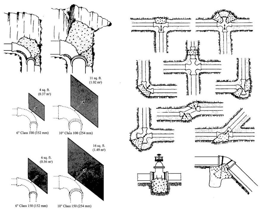
ADOPTED: 1975
REVISED: 1981, 1982, 2003, 2006
1.0 SCOPE.
1.1 This standard shall govern the installation of extra strength vitrified clay pipe in gravity building drains. (See Section 2.2 for allowable location.) Installation, material, and inspection shall comply with the current edition of the Uniform Plumbing Code [UPC]TM published by the International Association of Plumbing and Mechanical Officials and this standard.
Note: The following sections of the Uniform Plumbing Code apply to vitrified clay pipe.
| 103.5 | Inspections |
| 103.5.3 | Testing of Systems |
| 103.5.3.3 | Exceptions |
| 103.5.4.2 | Responsibility |
| 204.0 | Definitions, Building Drain |
| 310.0 | Workmanship |
| 313.0 | Protection of Piping, Materials, and Structures |
| 314.3 | Supporting in the Ground |
| 315.0 | Trenching, Excavation, and Backfill |
| 316.1.4 | Flare Joints |
| Chapter 7 | Sanitary Drainage |
| 701.1.3 | Location of piping and use in Pressurized Drainage Systems |
| 705.2 | Use of Joints |
| 712.2 | Water Test |
| 712.3 | Air Test |
| 720.0 | Sewer and Water Pipes |
| Table 14-1 | Extra Strength |
| Vitrified Clay Pipe | ASTM C 700 |
| Fittings, Couplings, | |
| Molded Rubber | ASTM C 425 |
| Chapter 2 | DEFINITIONS |
| Chapter 14 | |
| ASTM | American Society for Testing and Materials |
| IAPMO | International Association of Plumbing and Mechanical Officials |
| UPC | Uniform Plumbing Code published by IAPMO |
2.0 PRODUCT REQUIREMENTS.
2.1 Minimum Standards.
2.1.1 Materials. Pipe and fittings shall be a minimum 3 inch (76 mm) in size, "Extra Strength" and couplings shall be molded rubber sewer couplings. They shall conform to the applicable standards in Table 14-1 of the UPC. [UPC 301.1]
2.1.2 Markings.
2.1.2.1 Pipe and Fittings. Pipe and fitting markings shall be in accordance with ASTM C 700. [UPC 301.1.2]
2.1.2.2 Couplings. Couplings assemblies shall be marked with at least the following:
2.2 Burial and Separation.
2.2.1 Burial. Pipe and fittings shall be buried 12 inches (305 mm) minimum.
2.2.2 Separation. Pipe and fittings shall not be run or laid in the same trench with water piping unless both the following conditions are met:
2.3 Type of Joints.
Joints shall be made with couplings or with flexible compression factory fabricated joints. [UPC 316.0]
2.3.1 Use of Joints.
Transitions between clay and other materials shall be made with molded rubber sewer couplings and appropriate bushings or reducers. [UPC 705.2]
ADOPTED:1980
REVISED: 1982, 1985, 2003, 2006
1.0 SCOPE.
1.1 This standard shall govern the installation of CPVC piping (IPS pipe and SDR-11 tubing) in potable hot and cold water distributing systems within buildings. (For allowable locations and pressure, see Sections 2.9.2 and 2.9.4) Installation, material and inspection shall comply with the current edition of the UPC [UPC]TM, published by the International Association of Plumbing and Mechanical Officials, and shall also comply with this standard.
Note: The following sections of the Uniform Plumbing Code apply to CPVC IPS piping and SDR-11 tubing.
| 103.5 | Inspections |
| 301.1 | Minimum Standards |
| 310.0 | Workmanship |
| 311.0 | Prohibited Fittings and Practices |
| 313.0 | Protection of Piping, Materials and Structures |
| 314.0 | Hangers and Supports |
| 316.2.3 | Plastic Pipe to Other Materials |
| Chapter 6 | Water Supply and Distribution |
| Chapter 2* | Definitions | |
| 205.0 | CPVC | Chlorinated Poly (Vinyl Chloride) Pipe or tubing "Pipe" or "Piping" includes both pipe and piping, unless specified as "IPS Pipe" or "tubing". |
| Table 14-1 | |
| Chlorinated Poly (Vinyl Chloride) (CPVC) Plastic Hot and Cold Water Distribution System ASTM D 2846 | |
| Chlorinated Poly (Vinyl Chloride) (CPVC) Plastic Pipe, Schedules 40 and 80 ASTM F 441 | |
| Socket Type Chlorinated Poly (Vinyl Chloride) (CPVC) Plastic Pipe Fittings Schedule 40 ASTM F 438 | |
| Socket Type Chlorinated Poly (Vinyl Chloride) (CPVC) Plastic Pipe Fittings Schedule 80 ASTM F 439 | |
| Solvent Cements for Chlorinated Poly (Vinyl Chloride) (CPVC) Plastic Pipe and Fittings ASTM F 493 |
| *The first three numbers refer to the corresponding section of the UPC. | |
| ABBREVIATIONS | |
| ASTM | American Society for Testing and Materials |
| IAPMO | International Association of Plumbing and Mechanical Officials |
| UPC | Uniform Plumbing Code published by IAPMO |
1.2 Special Requirements for CPVC Installation within Residential Structures. [HCD 1]
In addition to the other requirements in the California Plumbing Code and this Appendix for the installation of CPVC Solvent Cemented Hot and Cold Water Distributions Systems, all installations of CPVC pipe within residential structures shall meet the following:
1.2.1 Flushing Procedures. All installations of CPVC pipe within residential structures shall be flushed twice over a period of at least one (1) week. The pipe system shall be first flushed for at least 10 minutes and then filled and allowed to stand for no less than 1 week, after which all the branches of the pipe system must be flushed long enough to fully empty the contained volume. At the time of fill, each fixture shall have a removable tag applied stating:
“This new plumbing system was first filled on (date) by (name). The California Department of Housing and Community Development requires that the system be flushed after standing at least one week after the fill date specified above. If the system is used earlier than one week after the fill date, the water must be allowed to run for at least two minutes prior to use for human consumption. This tag may not be removed prior to flushing, except by the homeowner.”
1.2.2 Worker Safety Measures. Mechanical ventilation sufficient to maintain exposures below the relevant exposure limits established by state regulation shall be provided in enclosed spaces. This ventilation shall be directed at the breathing zone of the worker installing the pipe. Where mechanical ventilation is not practical, respirators, suitable for organic vapors, shall be used. For the purpose of this subdivision, an enclosed space is defined as:
Installers of CPVC pipe withing residential structures shall use non-latex thin gauge (4 millimeters) nitrile gloves, or other gloves providing an equivalent or better degree of protection during the installation of the CPVC plumbing system. Gloves shall be provided to all workers by the contractor, or plumbing subcontractor, and shall be replaced upon contamination by cements.
2.0 PRODUCT REQUIREMENTS.
2.1 Minimum Standards.
2.1.1 Materials. Materials shall comply with the following:
| Materials | ASTM Standard |
|---|---|
| Raw Material-CPVC 23447 | D 1784 |
| IPS Pipe | |
| Sch. 40(½in.,¾ in. and 1 in.) | F 441 |
| (12.7 mm, 19.1 mm, and 25.4 mm) | |
| Sch. 80 (½ in. – 2 in.) | F 441 |
| (12.7 mm – 51 mm) | |
| Tubing | |
| SDR 11 (½ in. thru 2 in.) | D 2846 |
| (12.7 mm – 51mm) | |
| Fittings | |
| Sch. 40 (½ in., ¾ in. & 1 in.) | F 438 |
| (12.7 mm, 19.1 mm, and 25.4 mm) | |
| Sch. 80 (½ in. – 2 in.) | F 439 |
| (12.7 mm – 51mm) | |
| Tube Fittings (½ in. – 2 in.) | D 2846 |
| (12.7 mm – 51 mm) |
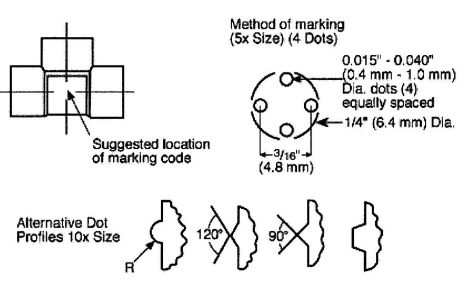
2.1.2 Primer. Listed primers shall be used that are compatible with the type of listed CPVC cement and pipe used. The primer shall be a true solvent for CPVC, containing no slow drying ingredient. Cleaners shall not be allowed to be used as a substitute or equivalent for a listed primer.
Exception:Listed solvent cements that do not require the use of primer shall be permitted for use with CPVC pipe and fittings, manufactured in accordance with ASTM D 2846, ½ inch through 2 inches in diameter.
Note: Manufacturer shall provide test data from an independent testing laboratory acceptable to the Administrative Authority that their CPVC pipe, together with recommended fittings has a Short Term Working Pressure (STWP) and Temperature Rating of 150 psi (1030 kPa) at 210°F (99°C) for 48 hours or more.
2.1.3 Material. Pipe and fittings are plastic and are usually light gray for IPS pipe and fittings, and tan for SDR 11 tubing and fittings.
2.2 Markings.
2.2.1 Pipe and Tubing. IPS pipe and tubing markings shall be in accordance with ASTM F 441 or ASTM D 2846. [UPC 301.1.2]
2.2.2 Fittings. Fitting markings shall be in accordance with ASTM F 438 or ASTM F 439 or ASTM D 2846. [UPC 301.1.2]
Note: Standard number may be omitted on smaller fittings when marked thus with four raised dots.
2.2.3 Solvent Cement. Container labeling of CPVC solvent cement shall be in accordance with ASTM F 493.
2.2.3.1 Color. Solvent cements requiring the use of a primer shall be colored orange. Solvent cements that do not require the use of a primer shall be colored yellow.
2.2.4 Primer. Primer container markings shall be in accordance with ASTM F 656.
2.2.4.1 Color. Primer shall be colored so as to make its use obvious on a finished joint, but shall not be colored orange or yellow.
2.2.5 Position of Markings. Identification markings shall be visible for inspection without moving materials.
2.2.6 Alignment. Piping and fittings shall be aligned properly without strain.
2.3 Protection of Materials.
2.3.1 Abrasion. Pipe or tubing passing through drilled or notched metal studs or joists or hollow shell masonry walls shall be protected from abrasion due to thermal expansion and contraction by elastomeric or plastic sleeves or grommets or other approved means. Straight runs may have protection at maximum 3 feet (915 mm) intervals. [UPC 313.30]
2.3.2 Puncture. Steel plate protection shall be installed when required by the Administrative Authority or Section 313.9 of the Uniform Plumbing Code.
2.3.3 Storage and Handling. Pipe shall be stored in a way to protect it from mechanical damage (slitting, puncturing, etc.). It shall be stored under cover to keep it clean and avoid long term exposure to sunlight. Exposure to sunlight during normal construction periods is not harmful. CPVC solvent cements should be stored in a cool place except when actually in use on the job site. The solvent cement manufacturer's specific storage instruction should be followed.
2.3.4 Freezing. In areas where the system must be drained to protect it from freezing, horizontal lines shall be graded to drain.
2.3.5 Overheating:
2.4 Thermal Expansion.
2.4.1 General. Allowance for thermal expansion and contraction shall be provided by approved means. Allowance shall be based on an expansion rate of 3.5 inches (89 mm) per 100 feet (30,480 mm) of length of run per 100°F (38°C) temperature change.
Note:Expansion rate is independent of the size of the pipe.
2.4.2 Offsets and Loops. Thermal expansion may be provided for by use of expansion loops, offsets, or changes of direction. From Table 1 determine the length "L" that is required. Note that "L" is based on length of run, diameter of pipe, and maximum temperature of water.
2.5 Clearance. Adequate clearance shall be provided between piping and structure (such as bored holes and sleeves) to allow for free longitudinal movement.
2.6 Hangers and Supports.
2.6.1 Vertical Piping. Vertical piping shall be supported at each floor or as specified by the design engineer to allow for expansion/contraction. Piping shall have a mid-story guide. [UPC 314.0]
2.6.2 Horizontal Piping. Unless an engineered design is provided and approved by the Administrative Authority, the following provisions shall apply. Horizontal piping 1 inch (25.4 mm) or smaller shall be supported at maximum 3 foot (914 mm) intervals. Piping 1¼ inch (32 mm) or larger shall be supported at maximum 4 foot (1219 mm) intervals.
2.6.3 Hangers and Anchors. Piping shall not be anchored rigidly to a support, but rather secured with smooth hangers or straps that provide for a degree of movement and that prevent damage to the pipe. Hangers or straps with sharp or abrasive edges shall not be used. Hangers that pinch the piping shall not be used.
2.7 Solvent Cement Joints.
2.7.1 SAFETY REQUIREMENTS AND PRECAUTIONS1
| NORMAL SIZE | LENGTH OF RUN IN FEET (mm) | ||||||||||
|---|---|---|---|---|---|---|---|---|---|---|---|
| 20 | (6096) | 40 | (12192) | 60 | (18288) | 80 | (24384) | 100 | (30480) | ||
| Inches | (mm) | LOOP LENGTH "L" IN INCHES (mm) | |||||||||
| ½ | (12.7) | 22 | (6706) | 31 | (9449) | 38 | (11582) | 44 | (13411) | 50 | (15240) |
| 3/4 | (19.1) | 26 | (7925) | 37 | (11278) | 46 | (14021) | 52 | (15850) | 58 | (17678) |
| 1 | (25.4) | 30 | (9144) | 42 | (12802) | 52 | (15850) | 60 | (18288) | 67 | (20422) |
| 1¼ | (32) | 33 | (10058) | 47 | (14326) | 57 | (17374) | 66 | (39917) | 74 | (22555) |
| 1½ | (38) | 36 | (10973) | 51 | (15545) | 62 | (18898) | 72 | (21946) | 80 | (24384) |
| 2 | (51) | 41 | (12497) | 58 | (17678) | 71 | (21641) | 82 | (24994) | 91 | (27737) |
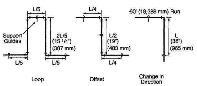
2.7.2 Selection. Follow the manufacturer's recommendations for type of solvent cements for such conditions as temperatures over 100°F (38°C), or humidity over 60%.
2.7.3 Handling (to maintain effectiveness). Package solvent cement in containers no larger than 1 quart (1 liter). Keep solvent cement can closed and in the shade when not in use. Keep applicator submerged in solvent cement between applications. Discard solvent cement when it thickens appreciably or gels. Solvent cement shall not be thinned.
2.7.4 Primer. A listed primer in compliance with ASTM F 656 shall be used with CPVC solvent cements that require the use of a primer. CPVC solvent cements that do not require the use of a primer are permitted for joints up to 2 inches in size.
2.7.5 Size of Applicator. Applicator should be about one half of the pipe diameter. Do not use small applicator on large pipes.
2.7.6 Procedures
Step 1. Cut pipe square with hand saw and mitre box, mechanical cutoff saw or tube cutter designed for plastic.
Step 2. Ream and chamfer pipe (to eliminate sharp edges, beads and all burrs).
Step 3. Clean all dirt, moisture and grease from pipe and fitting socket. Use a clean, dry rag.
Step 4. Check dry fit of pipe in fittings. Pipe should enter fitting socket ¼ to ¾ of socket depth. On larger sizes of Sch. 80 fittings, a looser fit may be expected. This is a normal condition, and requires care to apply an adequate amount of cement.
Step 5. Apply CPVC primer, if required (See Section 2.7.4) to inside of fitting socket. Take care to avoid puddling.
Step 6. Apply CPVC primer, if required to outside surface of pipe to depth of fitting socket.
Step 7. When using solvent cements requiring a primer wait until primer surface is tacky. DO NOT attempt to soften (dissolve) the surface as is required for PVC.v
Step 8. Apply a liberal coat of CPVC solvent cement to the outside surface of the pipe to the depth of the fitting socket.
Step 9. Apply a light coat of CPVC solvent cement to inside of fitting socket. Apply a second liberal coat of cement to the pipe end. Take particular care in cementing larger sizes of Sch. 80 fittings. Be sure all surfaces are coated.
Step 10. While both the inside socket surface and the outside surface of the pipe are WET with solvent cement, forcefully
1 Appendix X1. Safety Requirements And Precautions, from ASTM D 2564-88 Solvent Cements for Poly (Vinyl Chloride) (PVC) Plastic Pipe and Fittings is reprinted with permission from the American Society for Testing and Materials, 1916 Race St., Philadelphia, PA 19103, copyright.
bottom the pipe in the socket, giving the pipe a quarter turn while inserting, if possible.
Step 11. Hold the joint together for 10 to 15 seconds to assure that the pipe remains bottomed against the pipe stop.
Step 12. Do not disturb the joint for at least 30 minutes.
Note: The joint is weak until the cement is dry. If the joint is adjusted after it is set, the joint will be ruined. See Table 2 for recommended set time.
| TEMPERATURE RANGE OF PIPE AND FITTINGS DURING ASSEMBLY AND CURE | MINIMUM JOINT SET TIME, HRS. (STEP 12) | MINIMUM CURE TIME BEFORE TESTING, HRS. (STEP 14) | MINIMUM TIME BEFORE PUTTING SYSTEM INTO SERVICE AT 80N PSI/160°F (71°C), HRS. | ||
|---|---|---|---|---|---|
| PIPE SIZE | |||||
| °F | °C | ½ - 1 in. (12.7-25.4 mm) | 1¼-2 in. (32-51 mm) | ||
| 60-100 | 16-38 | ½ | 1 | 2 | 24 |
| 40-60 | 4-16 | 1 | 2 | 4 | 48 |
Step 13. Wipe excess cement from the pipe. A properly made joint will show a bead of cement around its entire perimeter. Any gaps may indicate insufficient cement.
Step 14. The system shall not be pressurized until the joints have cured (set) at least as long as recommended by the manufacturer. If the manufacturer's recommendation is not available, the following cure times are required.
2.7.7 Prohibited Joints. Piping shall not be threaded. Female screwed fittings, with CPVC threads, shall be prohibited. Joints made with adhesives shall be prohibited.
2.7.8 Threaded Joints. When threads are required, molded male adapters shall be used.
2.7.9 Location. CPVC threaded joints shall be accessible.
2.7.10 Lubricants. Only thread tape or thread lubricant approved specifically for use with CPVC shall be used. Conventional pipe thread compounds, putty, linseed oil based products, and unknown mixtures are prohibited.
2.7.11 Tightening. Joints shall be tightened approximately 1½ turns past hand tight.
CAUTION: Hand tight refers to the number of threads to reach hand tight with metal pipe. Small sizes of CPVC can be bottomed by hand pressure alone. DO NOT overtighten.
2.7.12 Special Joints.
2.7.12.1 Transition Joints. Transitions from CPVC tubing to metal piping and valves shall be made only with listed transition fittings suitable for that purpose. When required, the transition fittings shall be designed in such a manner that it can be anchored to a building member to prevent rotation. [UPC 316.2]
2.7.12.2 Soldering. Soldered metal joints shall not be made closer than 18 inches (457 mm) to any already installed plastic to metal adapter in the same water line.
2.7.12.3 Hose Bibbs. Hose bibbs shall be connected only to metal system components which are adequately anchored to the building structure. The CPVC plastic system shall terminate in wall.
2.8 Pressure Relief Valves.
2.8.1 CPVC Piping. CPVC piping used for temperature and/or pressure relief valve drain lines shall be graded to the outlet end and shall be supported at 3 foot (914 mm) intervals both vertically and horizontally.
2.9 Installation, Inspection and Testing.
2.9.1 Finish Nipples. Finish nipples shall be connected to drop ear elbows or other fittings listed for preventing rotation. Finish nipples shall not be CPVC but CPVC stub outs for fixture connections shall be permitted. [UPC 609.0]
2.9.2 Location. CPVC tubing shall not be installed so as to be subjected to direct sunlight after installation, and shall not be installed on the surface of the building unless it is protected by paint or a protective covering.
2.9.3 Water Heaters. There shall be a minimum of six (6) inches (152 mm) of metallic piping between a gas water heater connection and CPVC tubing. CPVC tubing may be installed downstream of instantaneous (coil or immersion) water heaters that the water heater temprature controls are maintained for maximum temperature 180° F.
2.9.4 Under Slab. Pipe shall be installed in trench with uniform support. Trenches shall be back-filled to a depth of six (6) inches (152 mm) with clean earth, sand or other approved material which shall not contain sharp rocks, boulders, cinder fill or other materials which would damage or break the piping. Pipe shall be stubbed up and all ends shall be capped. The system shall be filled with water and all air shall be bled off. The system shall be pressure tested under a water pressure which is not less than the working pressure which is not less than the working pressure under which it is to be used for a minimum of two (2) hours. All leaks shall be corrected. Foam pipe insulation shall be installed on all stub ups to prevent damage during concrete pour and finishing.
2.9.5 Identification. A permanent sign with the legible words "This building has non-metallic interior water piping" shall be fastened on or inside the main electric service panel.
2.9.6 Position of Marking. When installed, piping and fittings shall be positioned so that when practical, identifying markings shall be readily visible for inspection.
2.9.7 Testing. Air testing is prohibited.
2.10 Sizing.
2.10.1 Method. Piping shall be sized in accordance with UPC Section 610.0. When Appendix A is applicable, use Chart 1 or 2 as appropriate. Flow velocities shall be limited to a maximum of 8 feet per second (2.4 m/s). See Table 3. [UPC 610.1]
| PIPE SIZE | PIPE GPM | SCH.40 | PIPE GPM | SCH.80 | TUBING GPM | SDR 11 | |||
|---|---|---|---|---|---|---|---|---|---|
| Ft.* | FV** | Ft.* | FV** | Ft.* | FV** | ||||
| FU | FU | FU | FU | FU | FU | ||||
| *Flush Tank Fixture Units | **Flush Valve Fixture Units | ||||||||
| ½ | 8 | 9 | – | 6 | 7 | – | 5 | 6 | – |
| ¾ | 13 | 19 | – | 11 | 15 | – | 10 | 13 | – |
| 1 | 22 | 33 | – | 18 | 26 | – | 17 | 24 | – |
| 1¼ | 37 | 74 | 5 | 32 | 55 | 15 | 25 | 42 | 8 |
| 1½ | 51 | 129 | 50 | 44 | 104 | 36 | 35 | 66 | 20 |
| 2 | 81 | 295 | 170 | 74 | 245 | 124 | 59 | 170 | 73 |
| PIPE SIZE | PIPE L/min. | SCH.40 | PIPE L/min. | SCH.80 | TUBING L/min. | SDR 11 | |||
|---|---|---|---|---|---|---|---|---|---|
| Ft.* | FV** | Ft.* | FV** | Ft.* | FV** | ||||
| FU | FU | FU | FU | FU | FU | ||||
| *Flush Tank Fixture Units | **Flush Valve Fixture Units | ||||||||
| 12.7 | 30.3 | 9 | – | 22.7 | 7 | – | 18.9 | 6 | – |
| 19.1 | 49.2 | 19 | – | 41.6 | 15 | – | 37.9 | 13 | – |
| 25.4 | 83.3 | 33 | – | 68.1 | 26 | – | 64.3 | 24 | – |
| 32 | 140.0 | 74 | 5 | 121.1 | 55 | 15 | 94.6 | 42 | 8 |
| 38 | 193.0 | 129 | 50 | 166.5 | 104 | 36 | 132.5 | 66 | 20 |
| 51 | 306.6 | 295 | 170 | 280.1 | 245 | 124 | 223.3 | 170 | 73 |
ADOPTED: 1982
REVISED: 1984, 1985, 1989, 1990, 1991, 1992, 1993, 1995, 1996, 1997, 2000, 2003, 2005, 2006
CHART 1
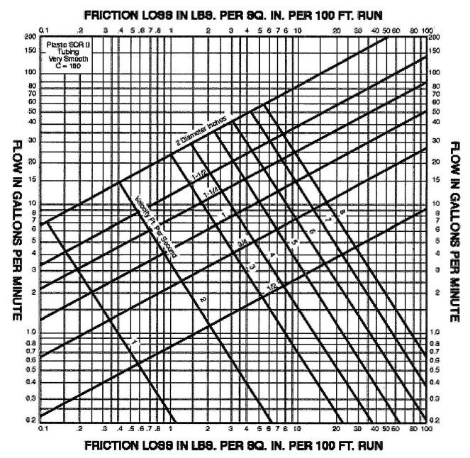
CHART 2
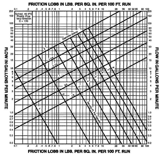
CHART 3
| CPVC PIPE SDR 11 (ASTM D 2846) CALCULATED LOOP (OFFSET) LENGTHS WITH ΔT OF APPROX. 80°F | ||||
|---|---|---|---|---|
| NOMINAL PIPE SIZE | LENGTH OF RUN IN FEET | |||
| 40 | 60 | 80 | 100 | |
| LOOP LENGTH (£) IN INCHES | ||||
| Assume Modulus & Stress at 160°F | ||||
| ½" | 22 | 27 | 31 | 34 |
| ¾" | 26 | 32 | 36 | 41 |
| 1" | 29 | 36 | 41 | 46 |
| 1 ¼" | 32 | 40 | 46 | 51 |
| 1 ½" | 35 | 43 | 50 | 56 |
| 2" | 40 | 49 | 57 | 64 |
| CPVC PIPE SCHEDULE 80 (ASTM F 441) CALCULATED LOOP (OFFSET) LENGTHS WITH ΔT OF APPROX. 80°F | ||||
|---|---|---|---|---|
| NOMINAL PIPE SIZE | LENGTH OF RUN IN FEET | |||
| 40 | 60 | 80 | 100 | |
| LOOP LENGTH (£) IN INCHES | ||||
| Assume Modulus & Stress at 160°F | ||||
| 2½" | 47 | 57 | 66 | 74 |
| 3" | 52 | 63 | 73 | 82 |
| 4" | 58 | 72 | 83 | 92 |
| 6" | 71 | 87 | 100 | 112 |
| 8" | 81 | 99 | 114 | 128 |
| 10" | 90 | 111 | 128 | 143 |
| CPVC PIPE SCHEDULE 11 (ASTM D 2846) CALCULATED LOOP (OFFSET) LENGTHS WITH ΔT OF APPROX. 100°F | |||||
|---|---|---|---|---|---|
| NOMIANL PIPE SIZE | LENGTH OF RUN IN FEET | ||||
| 20 | 40 | 60 | 80 | 100 | |
| LOOP LENGTH (£) IN INCHES | |||||
| Assume Modulus & Stress at 160°F | |||||
| ½" | 17 | 24 | 30 | 34 | 39 |
| ¾" | 20 | 29 | 35 | 41 | 46 |
| 1" | 23 | 33 | 40 | 46 | 52 |
| 1 ¼" | 26 | 36 | 44 | 51 | 57 |
| 1 ½" | 28 | 39 | 48 | 56 | 62 |
| 2" | 32 | 45 | 55 | 64 | 71 |
£ = √ 3ED(ΔL)/2S
where £ = loop length in inches
E = modulus of elasticity at maximum temperature, psi
D = outside diameter of pipe, inches
ΔL = change in length due to change in temperature, inches
S = working stress at maximum temperature, psi
| CPVC PIPE SCHEDULE 80 (ASTM F 441) CALCULATED LOOP (OFFSET) LENGTHS WITH ΔT OF APPROX. 100°F | ||||
|---|---|---|---|---|
| NOMINAL PIPE SIZE | LENGTH OF RUN IN FEET | |||
| 40 | 60 | 80 | 100 | |
| LOOP LENGTH (£) IN INCHES | ||||
| Assume Modulus & Stress at 160°F | ||||
| 2½” | 52 | 64 | 74 | 83 |
| 3” | 58 | 71 | 82 | 91 |
| 4” | 65 | 80 | 92 | 103 |
| 6” | 79 | 97 | 112 | 125 |
| 8” | 91 | 111 | 128 | 143 |
| 10” | 101 | 124 | 143 | 160 |
| THERMAL EXPANSION (INCHES) | ||
|---|---|---|
| LENGTH OF RUN (feet) | ΔT 80°F | ΔT 100°F |
| 20 | 0.65 | 0.82 |
| 40 | 1.31 | 1.63 |
| 60 | 1.96 | 2.45 |
| 80 | 2.61 | 3.26 |
| 100 | 3.26 | 4.08 |
Δ L = Lp X C X Δ T
Δ L = change in length of pipe in inches
Lp = length of pipe in inches
C = coefficient of thermal expansion for CPVC, 3.4 X 10⁵in/in °F
ΔT = change in temperature in °F
1.0 SCOPE.
This standard shall govern the installation of welded copper and copper alloy water tube in potable hot and cold water systems.Installation, material, and inspection shall comply with the current edition of the Uniform Plumbing Code [UPC]TMpublished by the International Association of Plumbing and Mechanical Officials and this standard.
Note: The following sections of the Uniform Plumbing Code apply to welded copper and copper alloy water tube.
| 103.5.3 | Test of Systems |
| 301.1 | Minimum Standards |
| 310.0 | Workmanship |
| 311.0 | Prohibited Fittings and Practices |
| 313.0 | Protection of Piping, Materials, and Structures |
| 314.0 | Hangers and Supports |
| 316.1 | Types of Joints |
| 316.1.2 | Wiped Joints |
| 316.1.3 | Soldered Joints |
| 316.2 | Special Joints |
| 316.2.1 | Copper Tubing to Screw Pipe Joints |
| 317.0 | Increasers and Reducers |
| Chapter 6 | Water Supply and Distribution |
| 604.0 | Materials |
| 604.1 | Water Pipe and Fittings |
| 604.2 | Water Tubing |
| 604.3 | Marking of Tubing |
| 604.4 | Flexible Water Connectors |
| 604.7 | Restriction of Used Piping |
| 606.1.1 | Flared Joints |
| 606.2.1 | Use of Joints, Copper Water Tube |
| 608.0 | Relief Valve Drains |
| 609.0 | Installation, Inspection, and Testing |
| 610.0 | Size of Portable Water Piping |
| 705.3.3 | Ground Joint, Flared or Ferrule Connections |
| 811.1 | Chemical or Industrial Waste |
| 903.2 | Use of Copper Tubing |
| Table 14-1 Standards | |
| ANSI B 16.18 | Cast Copper Alloy Solder Joint Pressure Fittings |
| ANSI B 16.22 | Wrought Copper and Copper Alloy Solder Joint Pressure Fittings |
| ASTM B 447 | Welded Copper Tube |
| Appendix A | Chart A-4 Friction Loss |
2.0 PRODUCT REQUIREMENTS.
2.1 Minimum Standards.
2.1.1 Materials. Materials shall comply with the appropriate standard in Table 14-1 of the UPC.
Note:The nominal or standard size of copper and copper alloy welded water tube is always 0.125 inch (3.8 mm) or 1/8 inch (3.8 mm) smaller than the actual outside diameter dimension of the tube. For example, 3 inch (76 mm) nominal size copper plumbing, tube measures 31/8 inch (79.2 mm) O.D., ½ inch (12.7 mm) nominal size copper plumbing tube measures 5/8 inch (15.9 mm) O.D., etc.
2.2 Use of Copper Tubing.
2.2.1 Markings. Markings shall be visible for inspection.
2.2.1.1 Water tube shall bear the following incised marked at not over 18 inch (457 mm) intervals:
2.2.1.2 All hard drawn tube shall be identified through out its entire length by a colored marking not less than 3/16 inch in height, including legend repeated at intervals not greater than 3 feet (914 mm). The legend shall include the type of tube, welded, ASTM specification, name or trademark of the manufacturer of both, and the country of origin. [UPC 604.3]
2.3 Joints.
2.3.1 General Information. Copper tube and fittings maybe joined in a number of ways, depending on the purpose of the system. Soldering and brazing with capillary fittings are the methods used most.
The American Welding Society defines soldering as a joining process which takes place below 840°F (449°C) and brazing as a similar process which occurs above 840°F (449°C) but below the melting point of the base metals. In actual practice for copper systems, most soldering is done at temperatures ranging from about 350°F to 550°F (177°to 288°C), while most brazing is done at temperatures ranging from 1100° F to 1500°F (593°C to 816°C). The choice between soldering or brazing will generally depend on operating conditions. Solder joints are generally used where the service temperature does not exceed 205°F (96°C), while brazed joints can be used where greater strength is required, or where system temperatures are as high as 400°F (204°C). [UPC 316.1]
2.3.2 Fittings for Soldered, Brazed, and Flared Joints.Fittings are available in all standard tube sizes and in a wide variety of types to cover needs for plumbing. They can be either soldered or brazed, although brazing cast fittings requires care. Wrought copper pressure fittings are also available over a wide range of sizes and types. These, too, can be joined by either soldering or brazing, and wrought fittings are preferred where brazing is the joining method. Otherwise, the choice between cast and wrought fittings is largely a matter of the user's preference. Flared-tube fittings provide metal-to-metal contact similar to ground joint unions; both can be easily taken apart and reassembled. They are especially useful where residual water cannot be removed from the tube and soldering is difficult. Flared joints may be required where a fire hazard exists and the use of a torch to make soldered or brazed joints is not allowed.
2.3.3 Solders.
Note: Users of the Uniform Plumbing Codes are reminded that provisions of the Federal Clean Drinking Act of 1986, which all must obey, forbid the use of solder which contains in excess of 0.2% of lead, by weight in potable water systems. The provisions of the act are incorporated in all ordinances, statutes, state and municipal regulations by reference and by operation of law.
The selection of a solder depends on the operating pressure and temperature of the line. Consideration should also be given to the stresses on the joint caused by thermal expansion and contraction. However, stresses due to temperature changes should not be significant in two commonly encountered cases: When tube lengths are short, or when expansion loops are used in long tube runs.
Solder is generally used in wire form, but paste-type solders are also available. These are finely granulated solders in suspension in a paste flux, When using paste-type solders, observe these four rules:
Solders are available containing small amounts of silver or other additives to impart special properties. Such solders may require special fluxes. The manufacturer's recommendations should be consulted regarding proper procedures and fluxes for such solders and about the expected properties.
2.3.4 Soldering Flux.
The functions of the soldering flux are to remove residual traces of oxides, to promote wetting, and to protect the surfaces to be soldered from oxidation during heating. The flux should be applied to clean surfaces and only enough should be used to lightly coat the areas to be joined.
An oxide film may reform quickly on copper after it has been cleaned. Therefore, the flux should be applied as soon as possible after cleaning.
CAUTION
Careless workmanship, especially during flux applications, can result in corrosion of the tube long after the system has been installed. If excessive flux is used, the residue inside the tube can cause corrosion. In an extreme case, such residual flux can actually lead to perforation through the tube wall causing leakage. To guard against this danger, it is important (1) to choose a flux that is not too corrosive, and (2) to use only the minimum amount actually needed to make the joint.
2.3.5 Solder Joints.
Soldering and brazing both involve basic steps, which must be executed with care and craftsmanship. The steps are:
Each step contributes to a strong, dependable joint.
2.3.5.1 Measuring.
Measuring the length of each tube segment must be accurate. Inaccuracy can compromise joint quality. If the tube it too short it will not reach all the way into the socket of the fitting and a proper joint cannot be made. If the tube segment is too long, there is danger of cocking the tube in the fitting and putting strain on the system which could affect service life.
2.3.5.2 Cutting.
Once the tube is measured it can be cut. Cutting can be accomplished in a number of different ways to produce a satisfactory square end. The tube can be cut with a disc-type tube cutter, a hacksaw, an abrasive wheel, or with a stationary or portable bandsaw. Care must be taken that the tube is not deformed while being cut. Regardless of method, the cut must be square with the run of the tube so that the tube will seat properly in the fitting socket.
2.3.5.3 Reaming.
All pipe and tube shall be reamed to the full I.D. of the pipe and tube.
Tools and used to ream tube ends include the reaming blade on the tube cutter, half-round or round files, a pocket knife, and a suitable deburring tool. With annealed tube, care must be taken not to deform the tube end by applying too much pressure. Both the inside and the outside of the tube may require removal of the burr.
2.3.5.4 Cleaning.
The removal of oxides and surface soil is crucial if filler metal is to flow properly into the joint. Unremoved oxide, surface soil, and oil can interfere with the strength of the joint and cause failure.
Mechanical cleaning is a simple operation. The end of the tube should be abraded lightly using sand cloth or nylon abrasive pads for a distance only slightly more than the depth of the fitting socket. The socket of the fitting should also be cleaned using sand cloth, abrasive pads, or a properly sized fitting brush.
Copper is a relatively soft metal. If too much material is removed, a loose fit will result and interfere with satisfactory capillary action in making the joint. The capillary space between the tube and fitting is approximately 0.004 inch (0.1 mm). Solder or brazing filler metal can fill this gap by capillary action. This spacing is critical for the filler metal to flow into the gap and form a strong joint.
Surfaces, once cleaned, should not be touched with bare hands or oily gloves. Skin oils, lubricating oils, and grease impair solder flow and wetting.
2.3.5.5 Fluxing.
Stir the flux before use. A good flux will dissolve and remove traces of oxide from the cleaned surfaces to be joined, protect the cleaned surfaces from reoxidation during heating and promote wetting of the surfaces by the solder. A thin, even coating of flux should be applied with a brush to both tube and fitting. Do not apply with fingers. Chemicals in the flux can be harmful if carried to the eyes or open cuts.
2.3.5.6 Assembly and Support.
After both tube and fitting surfaces are properly fluxed, they should be assembled, making sure the tube seats against the base of the fitting socket. A slight twisting motion ensures even distribution by the flux. Remove excess flux. Care must be taken to assure that the tube and fittings are properly supported with a uniform capillary space around the entire circumference of the joint. Uniformity of capillary space will ensure good filler metal penetration if the guideliness of successful joint making are followed. Excessive joint clearance can cause the filler metal to creck under stress or vibration.
The joint is now ready for soldering. Joints prepared and ready for soldering should be completed the same day and not left unfinished overnight.
2.3.5.7 Heating.
Because an open flame may be used for soldering, and because flammable gases are used, safety precautions must be observed. The heat is generally applied using an air/fuel touch. Such torches use acetylene or an LP gas. Electric resistance tools can also be used.
Heating should begin with the flame perpendicular to the tube. The copper tube conducts the initial heat into the fitting socket for even distribution of heat inside and out. The extent of this preheating depends upon the size of the joint. Experience will indicate the amount of time needed. The flame should now be moved into the fitting. Then move the flame from the fitting socket back onto the tube a distance equal to the depth of the fitting socket. Touch the solder to the joint. If the solder does not melt, remove it and continue the heating process. Be careful not the overheat or to direct the flame into the fitting cup. This could cause the flux to burn and destroy its effectiveness. When the melting temperature of the sodler has been reached, heat may be applied to the base of the cup to aid capillary action in drawing the solder into the cup.
2.3.5.8 Applying the Filler Metal.
For tube in a horizontal position, start applying the solder slightly off-center at the bottom of the joint. Proceed across the bottom of the fitting and up to the top center position. Return to the point of
beginning, overlap the starting point, and then proceed up the incompleted side to the top, again, overlapping the solder.
For joints in the vertical position, a similar sequence of overlapping passes should be made, starting wherever is convenient. Molten solder will be drawn into the joint by capillary action regardless of whether the solder is being fed upward, downward, or horizontally.
2.3.5.9 Cooling and Cleaning.
After the joint has been completed, natural cooling is best. Shock cooling with water may cause unnecessary stress on the joint and result in eventual failure. When cool, clean off any remaining flux with a wet rag.
2.3.6 Brazed Joints.
Brazing is the second most commonly used method for joining copper tube. Making brazed joints is similar to making soldered joints with respect to measuring, cutting, reaming, cleaning, assembly and support. And as in soldering, the brazing filler metal is melted by the heat of the tube and fitting and drawn into the joint by capillary action. [UPC 316.1.7]
The major differences between soldering and brazing are the:
2.3.6.1 Brazing Flux.
The fluxes used for brazing copper joints are different in composition from soldering fluxes. The two types cannot be used interchangeably. Brazing fluxes are water based, whereas most soldering fluxes are petroleum based. Similar to soldering fluxes, brazing fluxes dissolve and remove residual oxide from the metal surface, protect the metal from reoxidation during heating and promote wetting of the surfaces to be joined by the brazing filler metal.
Fluxes also provide the draftsman with an indication of temperature. Application of the flux is the same as when soldering. If the outside of the fitting and the heat-affected area of the tube are covered with flux (in addition to the end of the tube and the cup), oxidation will be prevented and the appearance of the joint will be greatly improved.
2.3.6.2 Brazing Filler Metals.
There are two general types of brazing filler metal used for joining copper tube. Classified according to their components, they are: BCuP (Brazing-Copper-Phosphorous) and BAg (Brazing-Silver).
BCuP filler metals are preferred for joining copper tube and fittings. The phosphorous in them acts as a fluxing agent and the lower percentage of silver makes them relatively low cost. When using copper tube, wrought copper fittings, and BCuP brazing filler metal, fluxing is optional. However, when cast fittings are brazed, flux must be used.
2.3.6.3 Heating.
Oxy/fuel torches are generally used for brazing because of the higher temperatures required.
Recent innovations in tip design make air/fuel torches useful on a wider range of sizes for brazing.
When working at brazing temperatures, safety precautions must be followed and care taken to protect both the operator and the materials being used.
The heating operation is the same as for soldering. First preheat the tube and then the tube and fitting. When the filler metal starts to melt, apply heat at the base of the fitting socket to help draw the brazing filler metal in by capillary action.
2.3.6.4 Applying Brazing Filler Metal.
Remember to allow the heat of the joint, not the flame, to melt the filler metal. The melted filler metal will be drawn into the joint by capillary action. It is very important that the flame be in continuous motion. It must not be allowed to remain on any one point long enough to burn through the tube or fitting.
If the filler metal fails to flow, or has the tendency to ball-up, it indicates either that there is oxide on the surfaces being joined or that the parts to be joined are not hot enough. If the filler metal refuses to enter the joint, the fitting cup is not hot enough. If it tends to flow over the outside of either part of the joint it indicates that part is over-heated. When the joint is completed, a continuous fillet should be visible completely around the joint.
Large diameter tube is more difficult to heat to the desired temperature. The use of a heating tip or rosebud may be necessary to maintain the proper temperature over the area being brazed. Once total heat control is attained, follow the same procedures used for smaller tube.
2.3.6.5 Cooling and Cleaning.
When the brazed joint is finished, allow it to cool naturally. Flux residues and some oxides formed by heating can be removed by washing with hot water and brushing with a stainless steel wire brush.
2.3.7 Flared Joints.
2.3.7.1 Flared Joints with Impact Flaring Tools:
Step 1 Cut the tube to the required length.
Step 2 Remove all burrs. This is very important to assure metal-to-metal contact.
Step 3 Slip the coupling nut over the end of the tube.
Step 4 Insert flaring tool into the tube end.
Step 5 Drive the flaring tool by hammer strokes, expanding the end of the tube to the desired flare. This requires a few moderately light strokes.
Step 6 Assemble the joint by placing the fitting squarely against the flare. Engage the coupling nut with the fitting threads. Tighten with two wrenches, one on the nut and one on the fitting [UPC 606.1.1]
2.3.7.2 Flared Joints with Screw-Type Flaring Tools:
Steps 1-3 Same as for impact flaring previously described.
Step 4 Clamp the tube in the flaring block so that the end of the tube is slightly above the face of the block.
Step 5 Place the yoke of the flaring tool on the block so that the beveled end of the compressor cone is over the tube end.
Step 6 Turn the compressor screw down firmly, forming the flare between the chamber in the flaring block and the beveled compressor cone.
Step 7 Remove the flaring tool. The joint can now be assembled as in Step 6 for impact flaring. [UPC 606.2.1]
2.4 Sizing.
2.4.1 Velocity.
Note: There are various hydraulic formulas for the flow of water in pipe. With high velocity and attendant turbulent flow, there can be excessive noise and piping wear.
The designer should aim for maximum flow velocities in the range of 5 to 8 feet per second (1.5—2.4 meters per second) to minimize noise and erosion problems. For the smallest tube sizes, the designer is wise to work at the bottom of this range, as a maximum, to guard against local high velocities building up due to faulty workmanship (e.g. burrs at tube ends which are not properly reamed) or unusually numerous changes in flow direction.
3.0 GENERAL INFORMATION.
3.1 It is not possible to cover all the variables of a plumbing system; however, the following information may prove helpful:
3.2 Expansion Loops – Copper tube, like all piping materials, expands and contracts with temperature changes. Therefore, in a copper tube system subjected to excessive temperature changes, the line tends to buckle or bend when it expands unless compensation is build into the system. Severe stresses on the joints may also occur. Such stresses, buckles, or bends are prevented by the use of expansion joints or by installing offsets, “U” bends, coil loops, or similar arrangements in the tube assembly. These specially shaped tube segments take up expansion and contraction without excessive stress. The expansion of a length of copper tube may be calculated from the formula:
Temperature Rise (°F) x length (feet) x 12 (inches per foot) x
Expansion Coefficient (inch per inch per °F) = Expansion (inches), or
Temperature Rise (°C) x Length (meter) x 1000 (mm per meter) x Expansion Coefficient (mm per mm per °C) = Expansion (mm).
Calculations for expansion and contraction should be based on the average coefficient of expansion of copper which is 0.0000094 per degree F (1.692 x 10⁻⁵ per degree C), between 70°F and 212° F (21° C and 100°C). For example, the expansion of each 100 feet (30.5 meters) of length of any size tube heated from room temperature (70°F) to 170°F (a 100°F (55.6°C) rise) is 1.128 inches (28.7 mm).
100°F x 100 feet x 12 inch/foot x 0.0000094 inch/inch/°F = 1.128 inch, or 55.6°C x 30.48 mm x 1000 mm/m x 1.692 x 10⁻⁵ mm/mm/°C = 28.7 mm
3.3 Tube Supports – See Section 314.0 and Table 3-2 of the Uniform Plumbing Code.
3.4 Bending– Copper tube, properly bent, will not collapse on the outside of the bend and will not buckle on the inside of the bend. Tests demonstrate that the bursting strength of a bent copper tube can be greater than it was before bending. Because copper is readily formed, expansion loops and other bends necessary in an assembly are quickly and simply made if the proper method and equipment are used. Simple hand tools employing mandrels, dies, forms, and fillers, or power-operated bending machines, are used.
3.4.1 Both annealed tube and bending-temper tube can be bent with hand benders. The proper size bender for each size tube must be used. Usually the size of the tool corresponds to the nominal outside diameter of the tube, not the standard tube size. For a guide to the typical bend readii, see the following bending guide for copper tube.
ADOPTED: 1980
REVISED: 1989, 2003, 2006
| TUBE SIZE IN. (mm) | TUBE TYPE | TEMPER | MINIMUM BEND RADIUS IN. (mm) | TYPE OF BENDING EQUIPMENT |
|---|---|---|---|---|
| * When bending by hand, without the use of bending equipment, a circular wooden disc iS used. The radius of the disc should be about ¼ to ½ inch (6.4 to 12.7 mm) less than the minimum bend radius shown. | ||||
| ¼ (6.4) | K, L | Annealed | ¾ (19.1) | Lever type |
| 3/8 (9.5) | K, L | Annealed | 1 ½ (38) | Lever or gear type |
| 3 (76) | None; by hand* | |||
| K, L, M | Drawn | 1 ¾ (45) | Gear Type | |
| ½ (12.7) | K, L | Annealed | 2 ¼ (57) | Lever or gear type |
| 4 ½ (114) | None; by hand* | |||
| K, L, M | Drawn | 2 ½ (64) | Gear Type | |
| ¾ (19.1) | K, L | Annealed | 3 (76) | Lever of gear type |
| K | 4 ½ (114) | None; by hand* | ||
| L | 6 (152) | None; by hand* | ||
| K | Drawn | 3 (76) | Gear type | |
| K, L | 4 (102) | Heavy-duty gear type | ||
| 1 (25.4) | K, L | Annealed | 4 (102) | Gear type |
| 7 ½ (191) | None; by hand* | |||
| 1¼(31.8) | K, L | Annealed | 9(229) | None; by hand* |
1.0 SCOPE.
1.1 This standard shall govern the Trenchless Installation of Polyethylene (PE) pipe for use in sanitary and storm sewers. The installed pipe shall comply with the requirements of the Uniform Plumbing Code (UPC)TM published by the International Association of Plumbing and Mechanical Officials (IAPMO) as to grade and connections to existing pipe and shall also comply with this standard.
Note: The following sections of the Uniform Plumbing Code apply.
| 103.5.3 | Testing of Systems |
| 103.5.4.2 | Responsibility |
| 103.5.5 | Other Inspections |
| 103.5.5.1 | Defective Systems |
| 103.6.2 | Other Connections |
| 218.0 | Definition of PE |
| 301.1 | Minimum Standards |
| 310.0 | Workmanship |
| 313.0 | Protection of Piping, Materials, and Structures |
| 315.0 | Trenching, Excavation, and Backfill |
| 316.2.3 | Plastic Pipe to Other Materials |
| Chapter 7 | Sanitary Drainage |
| 701.2 | Fittings |
ABREVIATIONS.
| ASTM | American Society for Testing Materials |
| IAPMO | International Association of Plumbing and Mechanical Officials |
| UPC | Uniform Plumbing Code |
2.0 PRODUCT REQUIREMENTS.
2.1 Minimum Standards.
2.1.1 Materials.
Materials shall comply with the following: The polyethyene pipe used is covered by the ASTM standards listed later in this standard. [UPC 301.1]
Materials
HDPE Extra High Molecular Weight 3408 SDR 17 Pipe Socket-Type PE Fittings for Outside Diameter-Controlled Polyethylene Pipe
Note: The HDPE 3408 SDR 17 pipe used in this process was selected because of its ability to retain its circular shape even when bent on a 4-foot radius during and after installation.
2.1.2 Table 14-1 Standards
ASTM D 2239
ASTM D 2447
ASTM D 2657
ASTM D 2683
ASTM D 3261
ASTM F 714
ASTM F 894
IAPMO PS 25
2.2 Protection of Pipe.
2.2.1 Stroage and Handling.
Pipe shall be stored in a way to protect it from mechanical damage (slitting, puncturing, etc.). It shall be stored under cover to keep it clean and avoid long term exposure to sunlight. Exposure to sunlight during normal construction periods is not harmful.
2.3 Types of Joints.
PE joints shall be made as follows:
2.3.1 Molded Rubber Coupling Joints.
Molded rubber coupling joints shall be installed in accordance with Appendix I of the UPC and with Section 705.1.6.
Shielded Coupling Joints.
Shielded coupling joints shall be installed in accordance with Appendix I of the UPC and with Section 705.1.8.
2.3.3 Hubless Cast Iron Pipe Joints.
Hubless cast iron pipe joints shall be installed in accordance with Appendix I of the UPC and with Section 705.1.9.
2.3.4 Heat Fusion Joints.
Heat fusion joints shall be made according to the manufacturer's procedure, installation instructions, and either ASTM D 2659 or ASTM D 3261.
2.4 Trenchless Installation of sewers will be as follows:
2.5 Cleanouts.
Cleanouts shall be installed in accordance with UPC Section 707.0
2.6 Inspections.
The completed piping shall be internally inspected by television camera unless waived by the Administrative Authority. [UPC 103.5]
2.7 Testing.
Completed piping shall be subjected to testing in accordance with Section 712.0 or 723.0 of the UPC.
ADOPTED: 1999
REVISED: 2002, 2003, 2006
1.0 SCOPE.
1.1 This standard shall govern the installation of Odor Control Systems for Water Closets. Installation, material and inspection shall comply with the requirements of the Uniform Plumbing Code (UPC)™ published by the International Association of Plumbing and Mechanical Officials (IAPMO) and this standard.
Note: The Building Official shall be consulted about penetration of fire separations, height and area or other limitations.
Note: The following sections of the Uniform Plumbing Code apply to Odor Control Systems for Water Closets.
| 103.5 | Inspection |
| Chapter 2 | Definitions |
| 301.1 | Minimum Standards |
| 310.0 | Workmanship |
| 311.0 | Prohibited Fittings and Practices |
| 311.8 | Screwed Fittings |
| 313.0 | Protection of Piping, Materials and Structures |
| 314.0 | Hangars and Supports |
| 316.0 | Joints and Connections |
| 316.4 | Prohibited Joints and Connections |
| 317.0 | Increasers and Reducers |
| Chapter 7 | Sanitary Drainage |
| 701.0 | Materials (Drainage) |
| 701.2 | Fittings |
| 903.0 | Materials (Venting) |
| 1101.3 | Material Uses |
| Table 14-1 | Materials |
| ASME B 16.23 | Cast Bronze Solder-Joint Drainage Fittings-DWV |
| ASME B 16.29 | Wrought Copper and Copper Alloy Solder-Joint Drainage Fittings |
| ASTM A 74 | Cast Iron Soil Pipe and Fittings |
| ASTM A 888 | Specification for Hubless Cast Iron Soil Pipe and Fittings for Sanitary and Storm Drain, Waste, and Vent Piping Applications |
| ASTM B 42 | Specification for Seamless Copper Pipe, Standard Sizes |
| ASTM B 302 | Specification for Threadless Copper Pipe, Standard Sizes |
| ASTM B 306 | Specification for Copper Drainage Tube (DWV) |
| ASTM B 828 | Standard Practice for Making Capillary Joints by Soldering of Copper and Copper Alloy Tube and Fittings |
| ASTM D 2564 | Solvent Cements for Poly (Vinyl Chloride) (PVC) Plastic Piping Systems |
| ASTM D 2661 | Aerylonitrile-Butadiene-Styrene (ABS) Sch. 40 Plastic Drain, Waste and Vent Pipe and Fittings |
| ASTM D 2665 | Poly (Vinyl Chloride) (PVC) Plastic Drain, Waste, and Vent Pipe and Fittings |
| ASTM D 3311 | Drain, Waste, and Vent (DWV) Plastic Fitting Patterns (note: although referenced in this standard, some of the fittings shown in the standard are not acceptable under the Uniform Plumbing Code.) |
| ASTM F 402 | Safe Handling of Solvent Cement, Primers, and Cleaners Used for Joining Thermoplastic Pipe and Fittings |
| ASTM F 628 | Acrylonitrile-Butadiene-Styrene (ABS) Sch. 40 Plastic Drain, Waste and Vent Pipe with a Cellular Core |
| ASTM F 656 | Primers for Use in Solvent Cement Joints of Poly (Vinyl Chloride) (PVC) Plastic Pipe and Fittings |
| ASTM F 891 | Coextruded Poly (Vinyl Chloride) (PVC) Plastic Pipe with a Cellular Core |
| CISPI 301 | Hubless Cast iron Soil Pipe and Fittings for Sanitary and Storm Drain, Waste and Vent Piping Applications |
| IAPMO IS 3 | Copper Plumbing Tube, Pipe and Fittings |
| IAPMO IS 5 | ABS Building Drain, Waste and Vent Pipe and Fittings |
| IAPMO IS 6 | Hubless Cast Iron Sanitary and Rainwater Systems |
| IAPMO IS 9 | PVC Building Drain, Waste and Vent Pipe and Fittings |
| UL 1004 | Electric Motors |
2.0 PRODUCT REQUIREMENTS.
2.1 Minimum Standards.
2.1.1 Materials.
All materials shall comply with the appropriate standards in Table 14-1 of the UPC.
2.1.2 All pipe and fittings shall be made from approved DWV materials and shall be installed in accordance with the requirements of Chapter 7 of the Uniform Plumbing Code entitled, Sanitary Drainage. In addition, all pipe and fittings shall be installed in accordance with the applicable IAPMO Installation Standard. [UPC 701.0]
2.2 Odor Control System Components.
2.2.1 Inlet Connection – The inlet for DWV odor control systems shall be connected at the tailpiece of the flushometer operated water closet using a listed tee. The tee shall immediately transition to the odor control riser using approved DWV pipe and fittings.
2.2.2 Riser – The odor control riser shall be made from listed DWV pipe no smaller than 2 ½ inch diameter. This minimum riser size was selected to adequately handle the required minimum odor control air flow rate. The riser height shall be a minimum of 6 feet as measured from the connection at the sanitary tee to the overhead connection at the odor control manifold. The minimum riser height was selected to adequately handle the maximum possible water rise generated during the flushometer flushing cycle.
2.2.3 Manifold – The odor control manifold, including all borizontal piping within the odor control system, shall be 1/8″ per foot horizontally sloped back to the last riser. The manifold shall be made from approved DWV material no smaller than the pipe size as determined by using Table 1 of this Installation Standard. No traps are permitted within the odor control piping system.
Note: The attached Figures 1 and 2 illustrate the basic configuration to be used for the design of any Odor Control System installed in accordance with this Installation Standard.
2.3 System Sizing.
2.3.1 Minimum Inlet Flow Rate - The odor control system shall provide a minimum average air flow rate of 5 cfm at each inlet connection (tee).
2.3.2 Minimum Inlet Draft- The odor control system shall provide a minimum average draft of ¼ inch WC (water column) as measured inside the inlet connection (tee), or minimum of 0.10 inch of WC at the small perforations in the top rim of the water closet bowl.
2.4 Exhaust Fan.
2.4.1 The exhaust fan shall be listed for installation in outdoor and wet locations and in conditioned air streams up to 140°F and shall comply with the applicable requirements of UL 1004.
2.4.2 The odor control system exhaust fan shall be in stalled in accordance with local building and electrical code requirements and shall comply with drainage venting termination requirements of the Uniform Plumbing Code.
2.5 System Testing.
2.5.1 Measure the suction pressure at any perforation of the water closet rim. The minimum reading should be 0.10 inch of water column.
Note: For conditions other than those covered in Table 1 the exhaust manifold and the main exhaust riser to the odor control system exhaust fan shall be sized to maintain an average air velocity of 300 ±50 feet per minute.
ADOPTED: 2001
REVISED: 2003
| MAXIMUM ALLOWABLE NUMBER OF WATER CLOSETS CONNECTED TO AN EXHAUST MANIFOLD | ||||||
|---|---|---|---|---|---|---|
| Pipe Diameter (inch) | 2½ | 3 | 4 | 5 | 6 | 8 |
| Maximum No. of Water Closets | 2 | 3 | 6 | 8 | 10 | 22 |
FIGURE 1
FIGURE 2
1.0 SCOPE.
1.1 This standard shall govern the installation of composite piping in potable hot and cold water distribution systems within and under buildings and shall apply only to PEX-AL-PEX and PE-AL-PE piping meeting the requirements of ASTMF 1281 and ASTM F 1282 and fittings meeting the requirements of ASTMF 1974. Installation, materials, and inspection should comply with the current edition of the Uniform Plumbing Code published by the International Association of Plumbing and Mechanical Officials, and shall also comply with this standard and manufacturer's installation recommendations.
Note: The following sections of the Uniform Plumbing Code shall apply to composite PEX-AL-PEX and PE-AL-PE tubing.
| *The first three numbers refer to the corresponding section of the UPC. | |
| 310.0 | Workmanship |
| 313.0 | Protection of Piping, Materials, and Structures |
| 316.1 | Types of Joints |
| 316.2.3 | Plastic Pipe to Other Materials |
| Chapter 6 | Water Supply and Distribution |
| Chapter 2* | DEFINITIONS |
| ASTM | American Society for Testing and Materials |
| IAPMO | International Association of Plumbing and Mechanical Officials |
| PEX-AL-PEX | Crosslinked Polyethylene-Aluminum-Crosslinked Polyethylene |
| PE-AL-PE | Polyethylene Aluminum–Polyethylene |
| UPC | Uniform plumbing Code as published by IAPMO |
2.0 PRODUCT REQUIREMENTS.
2.1 Materials and Fittings.
2.1.1 Materials. Materials shall comply with the following requirements:
| Materials | ASTM Standard |
|---|---|
| Crosslinked Polyethylene-Aluminum-Crosslinked Polyethylene (PEX-AL-PEX) | F 1281 |
| Polyethylene-Aluminum-Polyethylene(PE-AL-PE) | F 1282 |
| Metal Insert Fittings for PEX-AL-PEX and PE-AL-PE composite pipe | F 1974 |
2.1.2 Piping. PEX-AL-PEX composite pipe shall comply with ASTM F 1281. PE-AL PE composite pipe shall comply with ASTM F 1282.
2.1.3 Fittings. Fittings shall be metal insert type and shall comply with ASTM F 1974. Fittings are limited to the following types:
Note 1:Manufacturers of fittings shall recommend assembly procedures.
2.2 Markings.
2.2.1 Piping. Composite piping shall be legibly marked at intervals of not more than 5 ft. (1.5 m) with at least the following:
| PEX-AL-PEX (orange colored) | 200 psi | 125 psi |
| at 73° | at180°F | |
| PE-AL-PE (blue colored) | 200 psi | 100psi |
| at 73°F | at 180°F |
2.2.2 Fittings. Fittings shall be marked with at least the following:
2.2.3 Position of Markings. When practical, markings shall be visible for inspection. Markings shall be visible prior to installation.
2.3 Protection of Piping.
2.3.1 Abrasion. Piping passing through metallic studs, joists, or hollow masonry walls shall be protected from abrasion or sharp edges by elastomeric or plastic sleeves, grommets, conical shaped punch holes or other approved means.
2.3.2 Puncture. Steel plate protection, minimum 18 gauge, shall be installed when the tubing is within 1 in. (25 mm) of the nailing surface. [UPC 313.9]
2.4 Exposed Piping.
2.4.1 General. Where exposed tubing may be subjected to mechanical damage it must be protected.
2.4.2 Freezing. In areas where the system must be drained to protect the system from freezing, horizontal lines shall be graded to drain.
2.4.3 Storage. Piping shall be stored in a way to protect the system from mechanical damage (slitting, puncturing, etc.). Piping should be stored undercover to keep it clean and avoid long term exposure to sunlight. Consult piping manufacturer for recommended limits for outside storage.
2.5 Thermal Expansion.
2.5.1 General. The linear expansion rate for PEX-AL-PEX and PE- AL-PE is 1.56 in. (39.6 mm) per 100 ft. (30 m) of tube per 100°F (55°C) change in temperature. No accommodation for thermal expansion is required.
2.5.2 Clearance. Bored holes and sleeves shall provide adequate clearance between the piping and structure to allow for free longitudinal movement.
2.6 Hangers and Supports.
2.6.1 Vertical Piping. Vertical piping shall be supported at every floor. Piping shall have a midstory guide.
2.6.2 Horizontal Piping. Horizontal piping shall be suported according to the following Table 1.
| NOMINAL DIAMETER | SPACING |
|---|---|
| ½”, ¾”, and 1” | 8’-2” (2489 mm) |
2.6.3 Hangers and Anchors. Piping shall not be anchored rigidly to a support, but shall be secured with hangers or straps that provide for a degree of movement and that prevent damage to the tubing. Do not use hangers or straps with sharp or abrasive edges. Do not use hangers that pinch the piping. [UPC 314.0]
2.7 Inspection and Testing.
2.8 Joints and Connections.
2.8.1 Procedure. Piping should be cut with a pipe cutter designed specifically for composite pipe. Piping shall be cut square, i.e. perpendicular to the length. No other cutting methods shall be used and care must be taken to remove any excess material, flashing, or burrs.
2.8.2 Tools. Fitting manufacturer's recommended tool shall be used with the composite insert fitting systems. For specific procedures, follow the manufacturer's recommendations.
2.8.3 Transition Joints.
2.8.3.1 Fittings. Transitions for composite tubing to metal piping or valves shall be made only with transition fittings intended for that purpose.
2.8.4 Joints. Joints shall not be allowed in piping installed in or under a concrete slab resting on grade unless for repair within a building structure. All repair joints must be properly protected with a heat shrink sleeve. All slab penetrations shall be sleeved.
2.9 Pressure Relief Valves.
PEX-AL-PEX Piping. PEX-AL-PEX piping used for temperature and/or pressure relief valve drain lines shall be graded to the outlet end and shall be supported at a maximum of 8 ft. 2 in. (2,489 mm) interval horizontally. Vertical piping shall be supported at every floor. Vertical piping shall have a mid-story guide.
2.10 Installation.
2.10.1 Bends. Piping shall be installed by bending the composite pipe by hand to a minimum radius of 5 times the nominal pipe diameter. External bend supports or sleeves are not required as the composite piping is rigid after bending.
2.10.2 Damage. Kinked, buckled, gouged, or other obvious damaged pipe shall not be used.
2.10.3 Finish Nipples. Finish nipples shall be connected to drop ear fittings to prevent rotation. Finish nipples shall not be PEX.
2.10.4 Hose Bibs. The piping directly connected to any hose bib shall be so anchored that the load on the hose bib will not strain the composite piping.
2.10.5 Heated Joints. An open flame shall not be applied to PEX-AL-PEX or PE-AL-PE piping when brazing, soldering, or welding joints.
2.10.6 Working Pressure and Temperature. Long term working pressures for the PEX-AL-PEX shall not exceed a maximum of 125 psi (860 kPa) and the long term working temperature shall not exceed 180°F (82°C). Long term working pressures for the PE-AL-PE shall not exceed a maximum of 100 psi (690 kPa) and the long term working temperature shall not exceed 180°F (82°C).
2.10.7 Exposure to Sunlight. Only UV stabilized composite piping can be subjected to direct sunlight after installation and can be installed on the surface of the building. Composite pipe contains an ultraviolet (UV) inhibitor to withstand limited exposure to UV light. Manufacturer's recommends placing the unused portion of a coil back in the product's box rather than storing in the sunlight while not in use.
2.10.8 Water Heater Connections. PEX-AL-PEX or PE-AL-PE piping shall not be installed within the first eighteen inches (18) (457 mm) of piping connected to a water heater. [UPC 604.13.2]
2.10.9 Water Hammer Arrestors. A composite hot water system will withstand repeated pressure surges, well in excess of its rated pressure. The Uniform Plumbing Code requires a means of attenuating water hammer. Consequently, water hammer arrestors shall be required when solenoid valves or other quick closing devices are used in the system. In designing for such situations, it is advisable to consult the pipe or fittings manufacturer for recommended surge pressure limits. Water hammer and surge pressure calculations are reviewed in Chapter 7, AWWA Manual M-11. [UPC 609.10]
2.11 Sizing.
2.11.1 Method. Piping shall be sized in accordance with UPC Section 610.0.
When UPC Appendix A is applicable, use Table 2. Add equivalent lengths from Table 3 when determining developed length.
Maximum velocities through PEX-AL-PEX and PE-AL-PE copper alloy fittings shall be limited to eight (8) feet per second (fps) (2.4 mps) in cold water and five (5) feet per second (fps) (1.52 mps) in hot water. [UPC 610.0]
| FLOW RATE U.S. GPM | ½” | ¾” | 1” | |||
|---|---|---|---|---|---|---|
| HEAD LOSS psi/c.ft. | VELOCITY ft./s | HEAD LOSS psi/c.ft. | VELOCITY ft./s | HEAD LOSS psi/c.ft. | VELOCITY ft./s | |
| 0.1 | 0.02 | 0.2 | 0.002 | 0.07 | 0.001 | 0.04 |
| 0.2 | 0.1 | 0.4 | 0.01 | 0.1 | 0.002 | 0.08 |
| 0.3 | 0.2 | 0.6 | 0.02 | 0.2 | 0.005 | 0.1 |
| 0.4 | 0.3 | 0.7 | 0.03 | 0.3 | 0.009 | 0.2 |
| 0.5 | 0.5 | 0.9 | 0.04 | 0.3 | 0.01 | 0.2 |
| 0.6 | 0.6 | 1.1 | 0.05 | 0.4 | 0.02 | 0.3 |
| 0.7 | 0.9 | 1.3 | 0.07 | 0.5 | 0.02 | 0.3 |
| 0.8 | 101 | 1.5 | 0.09 | 0.5 | 0.03 | 0.3 |
| 0.9 | 1.4 | 1.7 | 0.1 | 0.6 | 0.04 | 0.4 |
| 1.0 | 1.6 | 1.8 | 0.1 | 0.7 | 0.05 | 0.4 |
| 2.0 | 5.9 | 3.7 | 0.5 | 1.3 | 0.2 | 0.9 |
| 3.0 | 12.5 | 5.5 | 1.0 | 2.0 | 0.4 | 1.3 |
| 4.0 | 21.3 | 7.3 | 1.8 | 2.6 | 0.6 | 1.7 |
| 5.0 | — | — | 2.7 | 3.3 | 0.9 | 2.1 |
| 6.0 | — | — | 3.8 | 4.0 | 1.3 | 2.5 |
| 7.0 | — | — | 5.0 | 4.6 | 1.7 | 3.0 |
| 8.0 | — | — | 6.4 | 5.3 | 2.2 | 3.4 |
| 9.0 | — | — | 8.0 | 5.9 | 2.7 | 3.8 |
| 10.0 | — | — | 9.7 | 6.6 | 3.3 | 4.2 |
| 11.0 | — | — | 11.6 | 7.2 | 3.9 | 4.6 |
| 12.0 | — | — | 13.6 | 7.9 | 4.6 | 5.0 |
| 13.0 | — | — | — | — | 5.3 | 5.5 |
| 14.0 | — | — | — | — | 6.1 | 5.9 |
| 15.0 | — | — | — | — | 6.9 | 6.3 |
| 16.0 | — | — | — | — | 7.8 | 6.3 |
| 17.0 | — | — | — | — | 8.7 | 6.7 |
| 18.0 | — | — | — | — | 9.7 | 7.1 |
| 19.0 | — | — | — | — | 10.7 | 7.6 |
| 20.0 | — | — | — | — | 11.8 | 8.0 |
| SIZES, (inches) | TYPE OF FITTINGS | EQUIVALENT LENGTH OF PIPE (feet) |
|---|---|---|
| ½ | Couplings Adapters Elbows Tees (Branch Flow) Tees (On the Run) | 2 2 7.5 8 2.5 |
| ¾ | Couplings Adapters Elbows Tees (Branch Flow) Tees (On the Run) | 2 2 8.5 10.5 2.5 |
| 1 | Couplings Adapters Elbows Tee (Branch Flow) Tees (On the Run) | 2 2 9 11 2.5 |
This standard shall govern the installation of Flexible PVC Hose (with solvent cemented joints) in Pools, Hot Tubs, Spas and Jetted Bathtubs.
Installation, materials and inspection shall comply with the current edition of the Uniform Swimming Pool Code and Uniform Plumbing Code published by the International Association of Plumbing and Mechanical Officials, and shall also comply with this Standard.
Note: The following sections of the Uniform Swimming Pool Code and Uniform Plumbing Code apply to Flexible PVC Hose.
| USPC | ||
| 201.0 | Definitions | |
| 310.0 | Piping | |
| 316.0 | Joints and Connections | |
| 319.0 | Tests | |
| Table 6-1 | Materials | |
| UPC | ||
| 218.0 | Definitions of PVC | |
| 310.0 | Workmanship | |
| 313.0 | Protection of Piping, materials, and Structures | |
| 315.0 | Backfilling | |
| Table 14-1 | Materials | |
| ABBREVIATIONS. | |
|---|---|
| ASTM | American Society for Testing and Materials |
| IAPMO | International Association of Plumbing and Mechanical Officials |
| UPC | Uniform Plumbing Code |
| USPC | Uniform Swimming Pool, [Spa and Hot Tub] Code |
1.0 MINIMUM STANDARDS.
1.1 Material. Materials shall perform to the appropriate standard in Table 6 - 1 of the Uniform Swimming Pool Code.
1.2 Applicable Standards. For applicable standards, see Table 6 - 1 of the Uniform Swimming Pool Code.
2.0 MARKINGS.
2.1 Hoses, fittings, solvent cement and primer used shall be marked with the designated IAPMO certification mark to show compliance with this standard.
3.0 PROTECTION OF HOSES.
3.1 Storage. Unprotected hose shall not be stored in direct sunlight. The hose shall be stored in a way to protect it from mechanical damage (slitting, puncturing, etc.). Exposure to sunlight during normal construction periods is not harmful. PVC solvent cement shall be stored in a cool place, except when actually in use at the job site. The solvent cement manufacturer's specific storage recommendations shall be followed.
3.2 Thermal Expansion. Hose shall be “snaked“ in the trench bottom with enough slack, at least 6 in. (152.4 mm) per 100 ft. (30.5 m), to compensate for thermal expansion and contration before stabilizing hose. Stabilize hose by bringing it approximately to operating temperature before testing and backfilling by one of the following methods:
3.3 Exposed Hose. Hose above grade when located on the exterior of the building or structure shall be protected from mechanical damage to the satisfaction of the Administrative Authority. Where exposed to sunlight, the hose shall be wrapped with at least 0.040 in. (1.0 mm) of tape or other approved method acceptable to the Administrative Authority.
4.0 TRENCHING, COVER, AND BACKFILL.
4.1 Trenching and Cover. Trench bottoms shall be uniformly graded and shall be of either undisturbed soil or shall consist of a layer or layers of compacted backfill so that minimum settlement will take place.
4.2 Backfill. Selected backfill shall be used to provide firm continuous support and proper compaction. Backfill over hose, except that joints shall be left exposed. After inspection and pressure test, complete backfill to a minimum of 12 in. (0.3 m) cover.
5.0 INSTALLATION.
5.1 Solvent Cement Joints.
5.1.1 Selection. Solvent cement shall be recommended for flexible PVC hose by the manufacturer. Follow manufacturer's recommendations for types of solvent cement for flexible PVC hose.
5.1.2 Handling (to maintain effectiveness). Use solvent cement in containers no larger than 1 quart (1 liter). Keep solvent cement can closed and in the shade when not in use. Keep applicator submerged in solvent cement between application. When solvent cement becomes thicker, THROW IT AWAY. Solvent cement shall NOT be thinned.
5.1.3 Size of Applicator. Follow manufacturer's recommendations.
5.1.4 Application. Follow manufacturer's recommendations.
5.1.5 General Principles.
5.1.5.1 To consistently make good joints, the following should be clearly understood and adhered to:
5.1.5.2 Penetration and dissolving can be achieved by the cement itself, by a suitable primer, or by the use of both primer and cement. A suitable primer will penetrate and dissolve the plastic more quickly than cement alone. In cold weather more time and additional applications are required (see Figure 1).
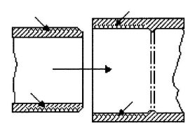
FIGURE 1
AREAS OF HOSE AND FITTINGS TO BE SOFTENED (DISSOLVED) AND PENETRATED
5.1.5.3 More than sufficient cement to fill the loose part of the joint must be applied (see Figure 2). Besides filling the gap, adequate cement layers will penetrate the surfaces and also remain wet until the joint is assembled.
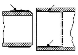
FIGURE 2
CEMENT COATINGS OF SUFFICIENT THICKNESS
5.1.5.4 If the cement coatings on the hose and fittings are wet and fluid when assembly takes place, they will tend to flow together and become one cement layer. Also, if the cement is wet the surfaces beneath them will still be soft, and these dissolved surfaces in the tight part of the joint will tend to fuse together (see Figure 3).
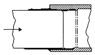
FIGURE 3
ASSEMBLY OF SURFACES WHILE THEY ARE WET AND SOFT
5.1.5.5 As the solvent dissipates, the cement layer and the dissolved surfaces will harden with a corresponding increase in joint strength. A good joint will take the required working pressure long before the joint is fully dry and final strength is obtained. In the tight (fused) part of the joint, strength will develop more quickly than in the looser (bonded) part of the joint. Completed joints should not be disturbed until they have cured sufficiently to withstand handling. Joint strength develops as the cement dries. Information about development of bond strength of solvent cemented joints is available (see Figure 4).
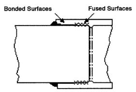
FIGURE 4 BONDED AND FUSED SURFACES OF JOINED HOSES
5.1.6 Procedure.
Note: Do not take SHORT CUTS. Most failures are caused by short cuts. DON'T TAKE A CHANCE.
Step 1 Cut hose square with hand saw and miter box, mechanical cut-off saw, or tube cutter designed for plastic.
Step 2 Ream and chamfer hose (to eliminate sharp edges, beads and all burrs).
Step 3 Clean all dirt, moisture, and grease from hose and fitting socket. Use a clean, dry rag.
Step 4 Check dry fit of hose in fitting. Hose should enter fitting socket from & to ¾ depth of socket.
Step 5 Soften inside socket surface by applying an aggressive primer which is a true solvent for PVC and is recommended by the manufacturer.
Step 6 Soften mating outside surface of hose to depth of socket by applying a liberal coat of the (aggressive) primer. Be sure entire surface is softened.
Step 7 Again coat inside socket surface with the (aggressive) primer. Then, without delay, apply solvent cement liberally to outside of hose. Use more than enough to fill any gaps.
Step 8 Apply a light coat of PVC solvent cement to inside of socket using straight outward strokes (to keep excess solvent out of socket). This is also to prevent solvent cement damage to hose. For loose fits, apply a second coat of solvent cement. Time is important at this stage. (See 5.1.4)
Step 9 While both the inside socket surface and the outside surface of the hose are SOFT and WET with solvent cement, forcefully bottom the hose in the socket, giving the hose a one-quarter turn, if possible. The hose must go to the bottom of the socket.
Step 10 Hold the joint together until tight.
Step 11 Wipe excess cement from the hose. A properly made joint will normally show a bead around its entire perimeter. Any gaps may indicate insufficient cement or the use of light bodied cement on larger diameters where heavy bodied cement should have been used.
Step 12 Do not disturb joint for the following periods:
30 minutes minimum at 60°F to 100°F (16°C to 38°C)
1CAUTION: Primers are toxic. Don't allow them to touch skin. Suitable gloves are advised.
1 hour minimum at 40°F to 60°F (4°C to 16°C)
2 hours minimum at 20°F to 40°F (-7°C to 4°C)
4 hours minimum at 0°F to 20°F (-18°C to -7°C)
Handle the newly assembled joints carefully during these periods. If gaps (step 11) or loose fits are encountered in the system, double these periods.
Step 13 The system shall not be pressurized until the joints have cured (set) at least as long as recommended by the manufacturer. If manufacturer's recommendation is not available, the cure times as shown in Table 1 are required.
5.1.7 Installation and Testing.
5.1.7.1 Installation. The hose shall be properly supported to prevent excessive sagging.
5.1.7.2 Testing.
Exception: All exposed equipment need not be tested as required in this section.
5.1.8 SAFETY REQUIREMENTS AND PRECAUTIONS1
5.1.8.1 General. Solvents contained in PVC plastic hose cements are classified as airborne contaminants and flammable and combustible liquids. Precautions listed in this section should be followed to avoid injury to personnel and the hazard of fire.
5.1.8.2 SAFETY PRECAUTIONS
| SIZES ½″ to 1¼″ 12.7 mm to 31.8 mm | SIZES 1½″ to 3″ 38.1 mm to 76.2 mm | SIZES 3½″ to 8″ 88.9 mm to 203.2 mm | ||||
|---|---|---|---|---|---|---|
| TEMP. RANGE DURING CURE PERIOD | UP TO 180 PSI (1240.2 kPa) | ABOVE 180 TO 370 PSI (1240.2 to 2549.3 kPa) | UP TO 180 PSI (1240.2 kPa) | ABOVE 180 TO 315 PSI (1240.2 to 2170.4 kPa) | UP TO 180 PSI (1240.2 kPa) | ABOVE 180 TO 315 PSI (1240.2 to 2170.4 kPa) |
| A. It is important to note that at temperatures colder than 20°F (-6.7°C) on sizes that exceed 3 in. (76.2 mm), test results indicate that many variables exist in the actual cure rate of the joint. The data expressed in these categories represent only estimated averages. In some cases, cure will be achieved in less time, but isolated test results indicate that even longer periods of cure may be required. | ||||||
| B. These cure schedules are based on laboratory test data obtained on Net Fit Joints (NET FIT = in a dry fit the pipe bottoms snugly in the fitting socket without meeting interference). The relative humidity in these tests was 50% or less. Higher relative humidity may require longer cure periods. | ||||||
| 60°F-100°F (16°C-38°C) | 1 hr | 6 hr | 2 hr | 12 hr | 6 hr | 24 hr |
| 40°F-60°F (4°C-16°C) | 2 hr | 12 hr | 4 hr | 24 hr | 12 hr | 48 hr |
| 10°F-40°F (-12°C+4°C) | 8 hr | 48 hr | 16 hr | 96 hr | 48 hr | 8 days |
ADOPTED: 1989
REVISED: 2003
1. Purpose and Scope
To ensure the proper installation of fittings and pumps to maintain no more than the maximum, allowed water retention for each system installed on each different make/model of bathtub. This is a field inspection to be done by the Administrative Authority, and because of this, there will be special, specific points of reference included in the installation instructions to locate jet-suction fitting-pump elevations.
2. Testing
To receive USPC listing, the manufacturer of the kit/or assembler of the whirlpool bath appliance shall provide sample tubs/systems to an approved testing laboratory and said tubs shall be tested to ANSI A 112.19.7M. The sample tubs shall represent the parameters described below:
| Tub Volume1 | No. of Jets | Pump Size2 | |
|---|---|---|---|
| 1As measured in gallon, to the overflow. | |||
| 2As rated in gallons per minute (GPM). | |||
| Sample #1 | Largest | Greatest | Largest |
| Sample #2 | Largest | Least | Smallest |
| Sample #3 | Smallest | Greatest | Largest |
| Sample #4 | Smallest | Least | Smallest |
3. Instructions
A complete set of installation instructions shall be provided with each appliance or kit and shall include the following:
4. Labeling Requirements
Labels shall be permanently affixed to the appliances to be visible from the access door upon final inspection. Labels shall contain the following information:
ADOPTED: 1990
REVISED: 2003
| Adopting Agency | BSC | SFM | HCD | DSA | OSHPD | CSA | DPH | AGR | DWR | CA | |||||||
|---|---|---|---|---|---|---|---|---|---|---|---|---|---|---|---|---|---|
| 1 | 2 | 1/AC | AC | SS | SS/CC | 1 | 2 | 3 | 4 | ||||||||
| Adopt Entire Chapter | X | X | X | X | X | ||||||||||||
| Adopt Entire Chapter as amended (amended sections listed below) | |||||||||||||||||
| Adopt only those sections that are listed below | |||||||||||||||||
| Chapter/Section | |||||||||||||||||
K 1.0 Private Sewage Disposal – General.
Exception: Where suitable sites outside of flood hazard areas are not available, disposal systems shall be permitted to be located in flood hazard areas on sites where the effects of inundation under conditions of the design flood are minimized.
Exception: The Authority Having Jurisdiction shall be permitted to, at its discretion, approve an alternate system.
K 2.0 Capacity of Septic Tanks.
The liquid capacity of all septic tanks shall conform to Tables K-2 and K-3 as determined by the number of bedrooms or apartment units in dwelling occupancies and the estimated waste/sewage design flow rate or the number of plumbing fixture units as determined from Table 7-3 of this Code, whichever is greater in other building occupancies. The capacity of any one (1) septic tank and its drainage system shall be limited by the soil structure classification, as specified in Table K-4.
K 3.0 Area of Disposal Fields and Seepage Pits.
The minimum effective absorption area in disposal fields in square feet (m2), and in seepage pits in square feet (m2) of sidewall, shall be predicated on the required septic tank capacity in gallons (liters) and/or estimated waste/sewage flow rate, whichever is greater, and shall conform to Table K-4 as determined for the type of soil found in the excavation, and shall be as follows:
Exception: In areas where the records or data indicate that the groundwaters are grossly degraded, the five (5) foot (1,524 mm) separation requirement shall be permitted to be reduced by the Authority Having Jurisdiction. The applicant shall supply evidence of groundwater depth to the satisfaction of the Authority Having Jurisdiction.
Exception: In areas where the records or data indicate that the groundwaters are grossly degraded, the ten (10) foot (3,048 mm) separation requirement shall be permitted to be reduced by the Authority Having Jurisdiction.
K 4.0 Percolation Test.
K 5.0 Septic Tank Construction.
K 6.0 Disposal Fields.
Exception: Listed or approved plastic leaching chambers shall be permitted to be used in lieu of pipe and filter material. Chamber installations shall follow the rules for disposal fields, where applicable, and shall conform to manufacturer's installation instructions.
| MINIMUM | MAXIMUM | |
|---|---|---|
| Number of drain lines per field | 1 | – |
| Length of each line | – | 100 feet (30,480 mm) |
| Bottom width of trench | 18 inches (457 mm) | 36 inches (914 mm) |
| Spacing of lines, center-to-center | 6 feet (1,829 mm) | – |
| Depth of earth cover of lines [preferred–18 inches (457 mm)] | 12 inches (305 mm) | – |
| Grade of lines | level | 3 in./100 ft. (25 mm/m) |
| Filter material under drain lines | 12 inches (305 mm) | – |
| Filter material over drain lines | 2 inches (51 mm) | – |
(See chart above.)
K 7.0 Seepage Pits.
Exception: When using a one- or two-piece concrete slab cover inlet, fitting shall be permitted to be a one-fourth (¼) bend fitting discharging through an opening in the top of the slab cover. On multiple seepage pit installations, the outlet fittings shall be per Section K 7.0 (B) of this appendix.
K 8.0 Cesspools.
K 9.0 Commercial or Industrial Special Liquid-Waste Disposal.
| Waste Flow Rate | ||||||||
| See Table K-3 of this appendix for estimated flow rates. | ||||||||
| Retention Times | ||||||||
| Commercial kitchen waste: | ||||||||
| Dishwasher and/or disposal | 2.5 hours | |||||||
| Single service kitchen: | ||||||||
| Single serving with disposal | 1.5 hours | |||||||
| Sand-silt oil | 2.0 hours | |||||||
| Lint-silt (laundry) | 2.0 hours | |||||||
| Storage Factors | ||||||||
| Fully equipped commercial kitchen | 8 hours operation: 1 | |||||||
| 16 hours operation: 2 | ||||||||
| 24 hours operation: 3 | ||||||||
| Single service kitchen | 1.5 | |||||||
| Auto washers | self-serve: 1.5 | |||||||
| employee operated: 2 | ||||||||
| Laundries, laundromats | 1.5 (allows for rock filter) | |||||||
| GREASE AND GARBAGE, COMMERCIAL KITCHENS | ||||||||
| Number of meals per peak hour | × | Waste flow rate | × | Retention time | × | Storage factor | = | Interceptor size (liquid capacity) |
| SAND-SILT OIL, AUTO WASHERS | ||||||||
| Number of vehicles per hour | × | Waste flow rate | × | Retention time | × | Storage factor | = | Interceptor size (liquid capacity) |
| SILT-LINT GREASE, LAUNDRIES, LAUNDROMATS | ||||||||
| Number of machines | × | 2 cycles per hour | × | Waste flow rate | × | Retention time=Storage Factor | = | Interceptor size (liquid capacity) |
K 10.0 Inspection and Testing.
K 11.0 Abandoned Sewers and Sewage Disposal Facilities.
K 12.0 Drawings and Specifications.
The Authority Having Jurisdiction, Health Officer, or other department having jurisdiction shall be permitted to require any or all of the following information before a permit is issued for a private sewage disposal system or at any time during the construction thereof.
| MINIMUM HORIZONTAL DISTANCE IN CLEAR REQUIRED FROM | BUILDING SEWER | SEPTIC TANK | DISPOSAL FIELD | SEEPAGE PIT OR CESSPOOL |
|---|---|---|---|---|
| Note: | ||||
| When disposal fields and/or seepage pits are installed in sloping ground, the minimum horizontal distance between any part of the leaching system and ground surface shall be fifteen (15) feet (4,572 mm). | ||||
| 1 Including porches and steps, whether covered or uncovered, breezeways, roofed porte cocheres, roofed patios, carports, covered walks, covered driveways, and similar structures or appurtenances. | ||||
| 2 See also Section 313.3 of the California Plumbing Code. | ||||
| 3 All drainage piping shall clear domestic water supply wells by not less than fifty (50) feet (15,240 mm). This distance may be reduced to not less than twenty five (25) feet (7,620 mm) when the drainage piping is constructed of materials approved for use within a building. | ||||
| 4 two (2) feet (610 mm) for each additional one (1) foot (305 mm) of depth in excess of one (1) foot (305 mm) below the bottom of the drain line. (See also Section K 6.0) | ||||
| 5 See Section 720.0 of the California Plumbing Code. | ||||
| 6 For parallel construction–For crossings, approval by the Health Department shall be required. | ||||
| 7 These minimum clear horizontal distances shall also apply between disposal fields, seepage pits, and the mean high-tide line. | ||||
| Building or structures1 | 2 feet (610 mm) | 5 feet (1,524 mm) | 8 feet (2,438 mm) | 8 feet (2,438 mm) |
| Property line adjoining private property | Clear2 | 5 feet (1,524 mm) | 5 feet (1,524 mm) | 8 feet (2,438 mm) |
| Water supply wells | 50 feet (15,240 mm) | 50 feet (15,240 mm) | 100 feet (30.5 m) | 150 feet (45.7 m) |
| Streams and other bodies of water | 50 feet (15,240 mm) | 50 feet (15,240 mm) | 1007 feet (30.5 m) | 150 feet7 (45.7 m) |
| Trees | – | 10 feet (3,048 mm) | – | 10 feet (3,048 mm) |
| Seepage pits or cesspools | – | 5 feet (1,524 mm) | 5 feet (1,524 mm) | 12 feet (3,658 mm) |
| Disposal field | – | 5 feet (1,524 mm) | 4 feet4(1,219 mm) | 5 feet (1,524 mm) |
| On-site domestic water service line | 1 foot5 (305 mm) | 5 feet (1,524 mm) | 5 feet (1,524 mm) | 5 feet (1,524 mm) |
| Distribution box | – | – | 5 feet (1,524 mm) | 5 feet (1,524 mm) |
| Pressure public water main | 10 feet6 (3,048 mm) | 10 feet (3,048 mm) | 10 feet (3,048 mm) | 10 feet (3,048 mm) |
| SINGLE-FAMILY DWELLINGS-NUMBER OF BEDROOMS | MULTIPLE DWELLING UNITS OR APARTMENTS-ONE BEDROOM EACH | OTHER USES: MAXIMUM FIXTURE UNITS SERVED PER TABLE 7-3 | MINIMUM SEPTIC TANK CAPACITY IN GALLONS (LITERS) |
|---|---|---|---|
| *Note: | |||
| Extra bedroom, 150 gallons (568 liters) each. | |||
| Extra dwelling units over 10:250 gallons (946 liters) each. | |||
| Extra fixture units over 100:25 gallons (95 liters) per fixture unit. | |||
| Septic tank sizes in this table include sludge storage capacity and the connection of domestic food waste disposal units without further volume increase. | |||
| 1 or 2 | – | 15 | 750 (2,839) |
| 3 | – | 20 | 1,000 (3,785) |
| 4 | 2 units | 25 | 1,200 (4,542) |
| 5 or 6 | 3 | 33 | 1,500 (5,678) |
| – | 4 | 45 | 2,000 (7,571) |
| – | 5 | 55 | 2,250 (8,517) |
| – | 6 | 60 | 2,500 (9,464) |
| – | 7 | 70 | 2,750 (10,410) |
| – | 8 | 80 | 3,000 (11,356) |
| – | 9 | 90 | 3,250 (12,303) |
| – | 10 | 100 | 3,500 (13,249) |
| TYPE OF SOIL | REQUIRED sq. ft. OF LEACHING AREA/100 gal. (m2/L) | MAXIMUM ABSORPTION CAPACITY IN gals./sq. ft. OF LEACHING AREA FOR A 24 HR. PERIOD (L/m2) | ||
|---|---|---|---|---|
| Coarse sand or gravel | 20 | (0.005) | 5.0 | (203.7) |
| Fine sand | 25 | (0.006) | 4.0 | (162.9) |
| Sandy loam or sandy clay | 40 | (0.010) | 2.5 | (101.8) |
| Clay with considerable sand or gravel | 90 | (0.022) | 1.1 | (44.8) |
| Clay with small amount of sand or gravel | 120 | (0.030) | 0.8 | (32.6) |
| REQUIRED SQUARE FEET OF LEACHING AREA/100 gal. SEPTIC TANK CAPACITY | MAXIMUM SEPTIC TANK SIZE ALLOWABLE | ||
|---|---|---|---|
| (m2/L) | (gallons) | (liters) | |
| 20–25 | (0.005–0.006) | 7,500 | (28,390) |
| 40 | (0.010) | 5,000 | (18,927) |
| 90 | (0.022) | 3,500 | (13,249) |
| 120 | (0.030) | 3,000 | (11,356) |
| Adopting Agency | BSC | SFM | HCD | DSA | OSHPD | CSA | DPH | AGR | DWR | CA | |||||||
|---|---|---|---|---|---|---|---|---|---|---|---|---|---|---|---|---|---|
| 1 | 2 | 1/AC | AC | SS | SS/CC | 1 | 2 | 3 | 4 | ||||||||
| Adopt Entire Chapter | |||||||||||||||||
| Adopt Entire Chapter as amended (amended sections listed below) | |||||||||||||||||
| Adopt only those sections that are listed below | |||||||||||||||||
| Chapter/Section | |||||||||||||||||
L 1.0 Scope.
L 1.1 The intent of this appendix is to provide clarification of procedures for the design and approval of engineered plumbing systems, alternate materials, and equipment not specifically covered in other parts of the code.
L 1.2 The provisions of this appendix apply to the design, installation, and inspection of an engineered plumbing system, alternate material, and equipment.
L 1.3 The Authority Having Jurisdiction has the right to require descriptive details of an engineered plumbing system, alternate material, or equipment including pertinent technical data to be filed.
L 1.4 Components, materials, and equipment must conform to standards and specifications listed in Table 14-1 of this code and other national consensus standards applicable to plumbing systems and materials.
L 1.5 Where such standards and specifications are not available, alternate materials and equipment must be approved per the provisions of Section 301.2 of this code.
L 2.0 Engineered Plumbing Systems.
L 2.1 Definition. Engineered Plumbing System: A system designed for a specific building project with drawings and specifications indicating plumbing materials to be installed, all as prepared by a person registered or licensed to perform plumbing design work.
L 2.2 Inspection and Installation. In other than one- and two-family dwellings, the designer of the system is to provide periodic inspection of the installation on a schedule found suitable to the Authority Having Jurisdiction. Prior to the final approval, the designer must verify to the Authority Having Jurisdiction that the installation is in compliance with the approved plans, specifications, and data and such amendments thereto. The designer must also certify to the Authority Having Jurisdiction that the installation is in compliance with the applicable engineered design criteria.
L 2.3 Owner Information. The designer of the system must provide the building owner with information concerning the system, considerations applicable for any subsequent modifications to the system, and maintenance requirements as applicable.
L 3.0 Water Heat Exchangers.
L 3.1 Heat exchangers used for heat transfer, heat recovery, or solar heating shall protect the potable water system from being contaminated by the heat-transfer medium.
L 3.2 Single-wall heat exchangers shall be permitted if they satisfy all of the following requirements:
Exception: Steam complying with Section L 3.2 (1) above.
L 3.3 Other heat exchanger designs shall be permitted to be permitted where approved by the Authority Having Jurisdiction.
L 4.0 Fixture Unit Values for Private or Private Use Bath-1 room Groups.
L 4.1 Tables L-1 and L-2 reflect the fixture unit loads for the fixtures in bathrooms as groups, rather than as individual fixtures. Such fixtures include water closets, lavatories, and bathtubs or showers. The tables reflect diversity in the use of fixtures within a bathroom and between multiple bathrooms.
L 4.2 The listed water supply fixture unit values in Table L-1 reflect the load of entire bathroom groups on the cold-water service. Individual hot and cold water branch piping to the fixtures should be sized according to Chapter 6 and Appendix A.
L 4.3 The listed drainage fixture unit values in Table L-2 reflect the load of entire bathroom groups on the sanitary drainage system. Where fixtures within bathrooms connect to different branches of the drainage system, the fixture unit values for the individual fixtures shall be used, as listed in Table 7-3 of this code.
L 5.0 Drainage System Sizing.
L 5.1 Definition. For the purposes of this code, this definition shall apply to this appendix.
Branch Interval. A length of soil or waste stack corresponding in general to a story height, but in no case less than eight (8) feet (2,438 mm), within which the horizontal branches from one floor or story of the building are connected to the stack.
L 5.2 Drainage Fixture Units. Drainage fixture unit values shall be sized in accordance with Table 7–3 and Section 702.0.
L 5.3 Size of Building Drain and Building Sewer. The maximum number of drainage fixture units allowed on the building drain or building sewer of a given size shall be in accordance with Table L-3. The minimum size of any building drain or building sewer serving a water closet shall be three (3) inches (80 mm).
| PRIVATE USE BATHROOM GROUP | SERVING 3 OR MORE PRIVATE USE BATHROOM GROUPS | |||
|---|---|---|---|---|
| COLD | HOT3 | COLD | HOT | |
| Notes: | ||||
| 1 A bathroom group, for the purposes of this table, consists of one water closet, up to two lavatories, and either one bathtub or one shower. | ||||
| 2 A half-bath or powder room, for the purposes of this table, consists of one water closet and one lavatory. | ||||
| 3 Multi-unit dwellings with individual water heaters use the same WSFU as for individual dwellings. | ||||
| Bathroom Groups Having up to 1.6 GPF Gravity-Tank Water Closets | ||||
| Half-bath or Powder Room | 3.5 | 0.8 | 2.5 | 0.5 |
| 1 Bathroom Group | 5.0 | 2.5 | 3.5 | 1.8 |
| 1 ½ Bathrooms | 6.0 | 2.5 | — | — |
| 2 Bathrooms | 7.0 | 3.5 | — | — |
| 2 ½ Bathrooms | 8.0 | 3.6 | — | — |
| 3 Bathrooms | 9.0 | 4.5 | — | — |
| Each Additional ½ Bath | 0.5 | 0.1 | — | — |
| Each Additional Bathroom Group | 1.0 | 0.5 | ||
| Bathroom Groups Having up to 1.6 GPF Pressure-Tank Water Closets | ||||
| Half-bath or Powder Room | 3.5 | 0.8 | 2.5 | 0.5 |
| 1 Bathroom Group | 5.0 | 2.5 | 3.5 | 1.8 |
| 1 ½ Bathrooms | 6.0 | 2.5 | — | — |
| 2 Bathrooms | 7.0 | 3.5 | — | — |
| 2 ½ Bathrooms | 8.0 | 3.6 | — | — |
| 3 Bathrooms | 9.0 | 4.5 | — | — |
| Each Additional ½ Bath | 0.5 | 0.1 | — | — |
| Each Additional Bathroom Group | 1.0 | 0.5 | — | — |
| Bathroom Group (1.6 GPF Flushometer Value) | 6.0 | 2.5 | 4.0 | 1.7 |
| Kitchen Group (Sink and Dishwasher) | 2.0 | 2.0 | 1.5 | 1.5 |
| Laundry Group (Sink and Clothes Washer) | 5.0 | 5.0 | 3.0 | 3.0 |
L 5.4 Size of Horizontal Branch or Vertical Stack. The maximum number of drainage fixture units allowed on a horizontal branch or vertical soil or waste stack of a given size shall be in accordance with Table L-4. Stacks shall be sized based on the total accumulated connected load at each story or branch interval.
L 5.4.1 Horizontal Stack Offsets. Horizontal stack offsets shall be sized in accordance with Table L-3 as required for building drains.
L 5.4.2 Vertical Stack Offsets. Vertical stack offsets shall be sized in accordance with Table L-4 as required for stacks.
L 5.5 Horizontal Stack Offset and Horizontal Branch Connections. Horizontal branch connections shall not connect to a horizontal stack offset or within two (2) feet (610 mm) above or below the offset where such horizontal offset is located more than four (4) branch intervals below the top of the stack.
L 6.0 Vent System Sizing.
L 6.1 Size of Vents. The size of vent piping shall be determined from the developed length and the total number of drainage fixture units connected thereto as set forth in Table L-6. Vents shall be not less than one-half (½) the required size of the drainage pipe size served as determined by Table L-4 for Horizontal Fixture Branches and Stacks nor less than one and one-quarter (1 ¼) inches (32 mm) in diameter. The drainage system shall be vented by not less than one (1) vent pipe which shall be not less than one-half the size of the required building drain and which shall extend from the building drain or extension of building drain to the outdoors. Vents shall be installed in accordance with Chapter 9.
L 6.2 Vent Stack. A vent stack shall be required for every drainage stack that extends five (5) or more branch intervals above the building drain or horizontal branch. The developed length of the vent stack shall be measured from the lowest connection of a branch vent to the termination outdoors.
L 6.3 Branch Vents. Where branch vents exceed forty (40) feet (12, 192 mm) in developed length, such vent shall be increased by one (1) pipe size for the entire developed length of the vent pipe.
L 6.4 Venting Horizontal Offsets. Drainage stacks with horizontal offsets shall be vented where five (5) or more branch intervals are located above the offset. The upper and lower section of the horizontal offset shall be vented in accordance with Sections L 6.4.1 and L 6.4.2.
| PRIVATE USE BATHROOM GROUP | SERVING 3 OR MORE PRIVATE USE BATHROOM GROUP | |
|---|---|---|
| Notes: | ||
| 1 A bathroom group, for the purposes of this table, consists of not more than one water closet, up to two (2) lavatories, and either one (1) bathtub or one (1) shower. | ||
| 2 A half-bath or powder room, for the purposes of this table, consists of one (1) water closet and one (1) lavatory. | ||
| Bathroom Groups having 1.6 GPF Gravity-Tank Water Closets | ||
| Half-bath or Powder Room | 3.0 | 2.0 |
| 1 Bathroom Group | 5.0 | 3.0 |
| 1 ½ Bathrooms | 6.0 | — |
| 2 Bathrooms | 7.0 | — |
| 2 ½ Bathrooms | 8.0 | — |
| 3 Bathrooms | 9.0 | — |
| Each Additional ½Bath | 0.5 | — |
| Each Additional Bathroom Group | 1.0 | — |
| Bathroom Groups having 1.6 GPF Pressure-Tank Water Closets | ||
| Half-bath or Powder Room | 3.5 | 2.5 |
| 1 Bathroom Group | 5.5 | 3.5 |
| 1 ½ Bathrooms | 6.5 | — |
| 2 Bathrooms | 7.5 | — |
| 2 ½ Bathrooms | 8.5 | — |
| 3 Bathrooms | 9.5 | — |
| Each Additional ½ Bath | 0.5 | — |
| Each Additional Bathrooms Group | 1.0 | — |
| Bathroom Group having 3.5 GPF Gravity-Tank Water Closets | ||
| Half-bath or Powder Room | 3.0 | 2.0 |
| 1 Bathroom Group | 6.0 | 4.0 |
| 1 ½ Bathrooms | 8.0 | — |
| 2 Bathrooms | 10.0 | — |
| 2 ½ Bathrooms | 11.0 | — |
| 3 Bathrooms | 12.0 | — |
| Each Additional ½ Bath | 0.5 | — |
| Each Additional Bathroom | 1.0 | — |
| Bathroom Group (1.6 GPF Flushometer Valve) | 3.0 | — |
| Bathroom Group (3.5 GPF Flushometer Valve) | 4.0 | — |
L 6.4.1 Venting Upper Section. The vent for the upper section of the stack shall be vented as a separate stack with a vent stack connection installed at the base of the drainage stack. Such vent stack shall connect below the lowest horizontal branch or building drain. Where vent stack connects to the building drain, the connection shall be located downstream of the drainage stack and within a distance of ten (10) times the diameter of the drainage stack.
L 6.4.2 Venting Lower Section. The vent for the lower section of the stack shall be vented by a yoke vent connecting between the offset and the next lower horizontal branch by means of a wye-branch fitting. The size of the yoke vent and connection shall not be less in diameter than that, the required size for the vent serving the drainage stack. The yoke vent connection shall be permitted to be a vertical extension of the drainage stack.
L 7.0 Vacuum Drainage Systems.
L 7.1 Vacuum drainage systems shall be considered engineered systems and shall comply with the requirements of Sections L 1.0 and L 2.0.
L 7.2 Vacuum drainage systems, including piping tank assemblies, vacuum pump assembly, and other components necessary for the proper function of the system shall be engineered and installed in accordance with the manufacturer's specifications. Plans and specifications shall be submitted to the Authority Having Jurisdiction for review and approval prior to installation.
L 7.3 Fixtures. Fixtures used in vacuum drainage systems shall comply with Sections L 1.4 and L 1.5.
L 7.4 Drainage Load. The pump discharge load from the collector tanks shall be in accordance with Chapter 7 of this code.
| DIAMETER OF PIPE | MAXIMUM NUMBER OF DRAINAGE FIXTURE UNITS FOR SANITARY BUILDING DRAINS AND RUNOUTS FROM STACKS | ||||
|---|---|---|---|---|---|
| SLOPE, in./ft (mm/m) | |||||
| in. | (mm) | 1¼(5.2) | ¼(10.4) | ¼(20.8) | ½(41.6) |
| SI: 1 inch = 25.4 mm, 1 inch per foot = 83.3 mm/m | |||||
| a On-site sewers that serve more than one building may be sized according to the current standards and specifications of the administrative authority for public sewers. | |||||
| b A maximum of two water closets or two bathroom groups, except in single-family dwellings, where a maximum of three water closets or three bathroom groups may be installed. | |||||
| 2 | (50) | — | — | 21 | 26 |
| 2 ½ | (65) | — | — | 24 | 31 |
| 3 | (80) | — | 20 | 42b | 50b |
| 4 | (100) | — | 180 | 216 | 250 |
| 5 | (125) | — | 390 | 480 | 575 |
| 6 | (150) | — | 700 | 840 | 1,000 |
| 8 | (200) | 1,400 | 1,600 | 1,920 | 2,300 |
| 10 | (250) | 2,500 | 2,900 | 3,500 | 4,200 |
| 12 | (300) | 2,900 | 4,600 | 5,600 | 6,700 |
| 15 | (380) | 7,000 | 8,300 | 10,000 | 12,000 |
| DIAMETER OF PIPE, | MAXIMUM NUMBER OF DRAINAGE FIXTURE UNITS | ||||
|---|---|---|---|---|---|
| in | (mm) | ANY HORIZONTAL FIXTURE BRANCHa | 1 STACK OF 3 OR FEWER BRANCH INTERVALS | STACKS WITH MORE THAN 3 BRANCH INTERVALS | |
| TOTAL FOR STACK | TOTAL AT 1 BRANCH INTERVAL | ||||
| SI: 1 inch = 25.4 mm | |||||
| aDoes not include branches of the building drain. | |||||
| bA maximum of two Water closets or bathroom groups within each branch interval or more than six water closets or bathroom groups on the stack. | |||||
| 1½ | (40) | 3 | 4 | 8 | 2 |
| 2 | (50) | 6 | 10 | 24 | 6 |
| 2 ½ | (65) | 12 | 20 | 42 | 9 |
| 3 | (80) | 20b | 48b | 72b | 20b |
| 4 | (100) | 160 | 240 | 500 | 90 |
| 5 | (125) | 360 | 540 | 1,100 | 200 |
| 6 | (150) | 620 | 960 | 1,900 | 350 |
| 8 | (200) | 1,400 | 2,200 | 3,600 | 600 |
| 10 | (250) | 2,500 | 3,800 | 5,600 | 1,000 |
| 12 | (300) | 3,900 | 6,000 | 8,400 | 1,500 |
| 15 | (380) | 7,000 | 6,000 | 8,400 | 1,500 |
L 7.5 Water Supply Fixture Units. Water supply fixture units shall be based on the values in Chapter 6 of this code. The load requirement of a vacuum-type water closet shall be determined per manufacturer's specification.
L 7.6 Traps and Cleanouts. For gravity fixtures, traps, and cleanouts shall be per approved plans.
L 8.0 Circuit Venting.
L 8.1 Circuit Vent Permitted. Circuit venting shall be designed by a registered professional engineer as an engineered design. A maximum of eight (8) fixtures connected to a horizontal branch drain shall be permitted to be circuit vented. Each fixture drain shall connect horizontally to the horizontal branch being circuit vented. The horizontal branch drain shall be classified as a vent from the most downstream fixture drain connection to the most upstream fixture drain connection to the horizontal branch.
L 8.1.1 Multiple Circuit-Vented Branches. Circuit vented horizontal branch drains are permitted to be connected together. Each group of a maximum of eight (8) fixtures shall be considered as separate circuit vent and shall conform to the requirements of this section.
L 8.2 Vent Size and Connection. The circuit vent shall be a minimum of two (2)inches (50 mm) in diameter and the connection shall be located between the two (2) most upstream fixture drains. The vent shall connect to the horizontal branch.
on the vertical. The circuit vent pipe shall not receive the discharge of any soil or waste.
L 8.3 Slope and Size of Horizontal Branch. The maximum slope of the vent section of the horizontal branch drain shall be one (1) inch per foot (83.2 mm/m). The entire length of the vented section of the horizontal branch drain shall be sized for the total drainage discharge to the branch.
L 8.3.1 Size of Multiple Circuit Vent. Multiple circuit vented branches shall be permitted to connect on the same floor level. Each separate circuit-vented horizontal branch that is interconnected shall be sized independently in accordance with Section L 8.3. The downstream circuit vented horizontal branch, shall be sized for the total discharge into the branch, including the upstream branches and the fixtures within the branch.
L 8.4 Relief Vent. A two (2) inch (50 mm) relief vent shall be provided for circuit-vent horizontal branches receiving the discharge of four or more water closets and connecting to a drainage stack that receives the discharge of soil or waste from upper horizontal branches.
L 8.4.1 Connection and Installation. The relief vent shall connect to the horizontal branch drain between the stack and the most downstream fixture drain of the circuit vent. The relief vent shall be installed on the vertical to the horizontal branch.
L 8.4.2 Fixture Drain or Branch. The relief vent is permitted to be a fixture drain or fixture branch for a fixture located within the same branch interval as the circuit vented horizontal branch. The maximum discharge to a relief vent shall be four fixture units.
L 8.5 Additional Fixtures. Fixtures, other than the circuit-vented fixtures, are permitted to discharge to the horizontal branch drain. Such fixtures shall be located on the same floor as the circuit-vented fixtures and shall be either individually or common vented.
L 9.0 Single-Stack Vent System.
L 9.1 Where Permitted. Single-stack venting shall be designed by a registered professional engineer as an engineered design. A drainage stack shall be permitted to serve as a single-stack vent system when sized and installed in accordance with Sections L 9.2 through L 9.9. The drainage stack and branch piping in a single-stack vent system shall provide for the flow of liquids, solids, and air without the loss of fixture trap seals.
L 9.2 Stack Size. Drainage stacks shall be sized according to Table L-5. A maximum of two (2) water closets shall be permitted to discharge to a three (3) inch (80 mm) stack. Stacks shall be uniformly sized based on the total connected drainage fixture unit load, with no reductions in size.
L 9.2.1 Stack Vent. The drainage stack vent shall have a stack vent of the same size terminating to the outdoors.
L 9.3 Branch Size. Horizontal branches connecting to a single-stack vent system shall be sized according to Table 7-5.
Exceptions:
- A maximum of one water closet within eighteen (18) inches (457 mm) of the stack horizontally shall be permitted on a three (3) inch (80 mm) horizontal branch.
- A water closets within eighteen (18) inches (457 mm) of a stack horizontally and one other fixture with up to (1½) inch (40 mm) fixture drain size shall be permitted on a three (3) inch (80 mm) horizontal branch when connected to the stack through a sanitary tee.
L 9.4 Length of Horizontal Branches.
L 9.4.1 Water closets shall be no more than four (4) feet (1,219 mm) horizontally from the stack.
Exception: Water closets shall be permitted to be up to eight (8) feet (2,438 mm) horizontally from the stack when connected to the stack through a sanitary tee.
L 9.4.2 Fixtures other than water closets shall be not less than twelve (12) feet (3.658 mm) horizontally from the stack.
L 9.4.3 The length of any vertical piping from a fixture trap to a horizontal branch shall not be considered in computing the fixture's horizontal distance from the stack.
L 9.5 Maximum Vertical Drops From Fixtures. Vertical drops from fixture traps to horizontal branch piping shall be one size larger, than the trap size, but not less than two (2) inch (50 mm) in diameter. Vertical drops shall be four (4) feet (1,219 mm) maximum length. Fixture drains that are not increased in size, or have a vertical drop exceeding 4 feet (1,219 mm) shall be individually vented.
L 9.6 Additional Venting Required. Additional venting shall be provided when more than one water closet is on a horizontal branch and where the distance from a fixture trap to the stack exceeds the limits in Section L 9.4. Where additional venting is required, the fixture(S) shall be vented by individual vents, common vents, wet vents, circuit vents, or a combination waste and vent pipe. The dry vent extensions for the additional venting shall connect to a branch vent, vent stack, stack vent, or be extended outdoors and terminate to the open air.
L 9.7 Stack Offsets. Where there are no fixture drain connections below a horizontal offset in a stack, the offset does not need to be vented. Where there are fixture drain connections below a horizontal offset in a stack, the offset shall be vented. There shall be no fixture connections to a stack within two (2) feet (610 mm) above and below a horizontal offset.
L 9.8 Separate Stack Required. Where stacks are more than two (2) stories high, a separate stack shall be provided for the fixtures on the lower two (2) stories. The stack for the lower two (2) stories shall be permitted to be connected to the branch of the buildings drain that serves the stack for the upper stories at a point that is not less than ten (10) pipe diameters downstream from the base of the upper stack.
L 9.9 Sizing Building Drains and Sewers. In a single-stack vent system, the building drain and branches there of shall be sized in accordance with Table 7-5, and the building sewer shall be sized in accordance with Table 7-8.
| MAXIMUM CONNECTED DRAINAGE FIXTURE UNITS | ||||
|---|---|---|---|---|
| STACK SIZE | STACKS LESS THAN 75 FEET IN HEIGHT | STACK 75 FEET TO LESS THAN 160 FEET IN HEIGHT | STACK 160 FEET OR GREATER IN HEIGHT | |
| in. | (mm) | |||
| SI: 1 inch = 25.4 mm | ||||
| 3 | (80) | 24 | NP | NP |
| 4 | (100) | 225 | 24 | NP |
| 5 | (125) | 480 | 225 | 24 |
| 6 | (150) | 1,015 | 480 | 225 |
| 8 | (200) | 2,230 | 1,015 | 480 |
| 10 | (250) | 4,500 | 2,320 | 1,015 |
| 12 | (300) | 8,100 | 4,500 | 2,320 |
| 15 | (380) | 13,600 | 8,100 | 4,500 |
| SIZE OF SOIL OR WASTE STACK, in (mm) | FIXTURE UNITS CONNECTED | DIAMETER OF VENT REQUIRED, in. (mm) | ||||||||
|---|---|---|---|---|---|---|---|---|---|---|
| 1¼(32) | 1½(40) | 2½(50) | 2frac12;(65) | 3 (80) | 4 (100) | 5 (125) | 6 (150) | 8 (200) | ||
| MAXIMUM LENGTH OF VENT, ft (m) | ||||||||||
| SI: 1 inch = 25.4 mm | ||||||||||
| 1½(40) | 8 | 50 (15.2) | 150 (45.7) | — | — | — | — | — | — | — |
| 2 (50) | 12 | 30 (9.1) | 75 (22.8) | 200 (61) | — | — | — | — | — | — |
| 2 (50) | 20 | 26 (7.9) | 50 (15.2) | 150 (45.7) | — | — | — | — | — | — |
| 2½(65) | 42 | — | 30 (9.1) | 100 (30.5) | 300 (91.4) | — | — | — | — | — |
| 3 (80) | 10 | — | 30 (9.1) | 100 (30.5) | 600 (182.9) | — | — | — | — | — |
| 3 (80) | 30 | — | — | 60 (18.3) | 200 (61) | 500 (152.4) | — | — | — | — |
| 4 (100) | 100 | — | — | 35 (10.7) | 100 (30.5) | 260 (79.2) | 1000 (304.8) | — | — | — |
| 4 (100) | 200 | — | — | 30 (9.1) | 90 (27.4) | 250 (76.2) | 900 (274.3) | — | — | — |
| 4 (100) | 500 | — | — | 20 (6.1) | 70 (21.3) | 180 (54.9) | 700 (213.4) | — | — | — |
| 5 (125) | 200 | — | — | — | 35 (10.7) | 80 (27.8) | 350 (106.7) | 1000 (304.8) | — | — |
| 5 (125) | 500 | — | — | — | 30 (9.1) | 70 (21.3) | 300 (91.4) | 900 (274.3) | — | — |
| 5 (125) | 1100 | — | — | — | 20 (6.1) | 50 (15.2) | 200 (61) | 700 (213.4) | — | — |
| 6 (150) | 350 | — | — | — | 25 (7.6) | 50 (15.2) | 200 (61) | 400 (122) | 1300 (396.6) | — |
| 6 (150) | 620 | — | — | — | 15 (4.6) | 30 (9.1) | 125 (38) | 300 (91.4) | 1100 (335.3) | — |
| 6 (150) | 960 | — | — | — | — | 24 (7.3) | 100 (30.5) | 250 (76.2) | 1000 (304.8) | — |
| 6 (150) | 1900 | — | — | — | — | 20 (6.1) | 70 (21.3) | 200 (61) | 700 (213.0) | — |
| 8 (200) | 600 | — | — | — | — | — | 50 (15.2) | 150 (43.7) | 500 (152.4) | 1300 (396.6) |
| 8 (200) | 1400 | — | — | — | — | — | 40 (12.2) | 100 (30.5) | 400 (122) | 1200 (365.8) |
| 8 (200) | 2200 | — | — | — | — | — | 30 (9.1) | 80 (27.8) | 350 (106.7) | 1100 (335.3) |
| 8 (200) | 3600 | — | — | — | — | — | 25 (7.6) | 60 (18.3) | 250 (76.2) | 800 (243.8) |
| 10 (250) | 1000 | — | — | — | — | — | — | 75 (22.9) | 125 (38) | 1000 (304.8) |
| 10 (250) | 2500 | — | — | — | — | — | — | 50 (15.2) | 100 (30.5) | 500 (152.4) |
| 10 (250) | 3800 | — | — | — | — | — | — | 30 (9.1) | 80 (27.8) | 350 (106.7) |
| 10 (250) | 5600 | — | — | — | — | — | — | 25 (7.6) | 60 (18.3) | 250 (76.2) |
”The information contained in these tables are not part of this American National Standard (ANS) and have not been processed in accordance with ANSI's requirements for an ANS. As such, these tables may contain materials that has not been subjected to public review or a consensus process. In addition, they do not contain requirements necessary for conformance to the standard.”
| AREAS AND CIRCUMFERENCES OF CIRCLES | |||||
|---|---|---|---|---|---|
| DIAMETER | CIRCUMFERENCE | AREA | |||
| Inches | mm | Inches | mm | Inches2 | mm2 |
| 1/8 | 6 | 0.40 | 10 | 0.01227 | 8.0 |
| 1/4 | 8 | 0.79 | 20 | 0.04909 | 31.7 |
| 3/8 | 10 | 1.18 | 30 | 0.11045 | 71.3 |
| 1/2 | 15 | 1.57 | 40 | 0.19635 | 126.7 |
| 3/4 | 20 | 2.36 | 60 | 0.44179 | 285.0 |
| 1 | 25 | 3.14 | 80 | 0.7854 | 506.7 |
| 1-1/4 | 32 | 3.93 | 100 | 1.2272 | 791.7 |
| 1-1/2 | 40 | 4.71 | 120 | 1.7671 | 1,140.1 |
| 2 | 50 | 6.28 | 160 | 3.1416 | 2,026.8 |
| 2-1/2 | 65 | 7.85 | 200 | 4.9087 | 3,166.9 |
| 3 | 80 | 9.43 | 240 | 7.0686 | 4,560.4 |
| 4 | 100 | 12.55 | 320 | 12.566 | 8,107.1 |
| 5 | 125 | 15.71 | 400 | 19.635 | 12,667.7 |
| 6 | 150 | 18.85 | 480 | 28.274 | 18,241.3 |
| 7 | 175 | 21.99 | 560 | 38.485 | 24,828.9 |
| 8 | 200 | 25.13 | 640 | 50.265 | 32,428.9 |
| 9 | 225 | 28.27 | 720 | 63.617 | 41,043.1 |
| 10 | 250 | 31.42 | 800 | 78.540 | 50,670.9 |
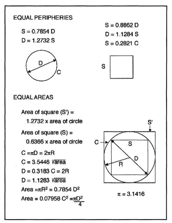
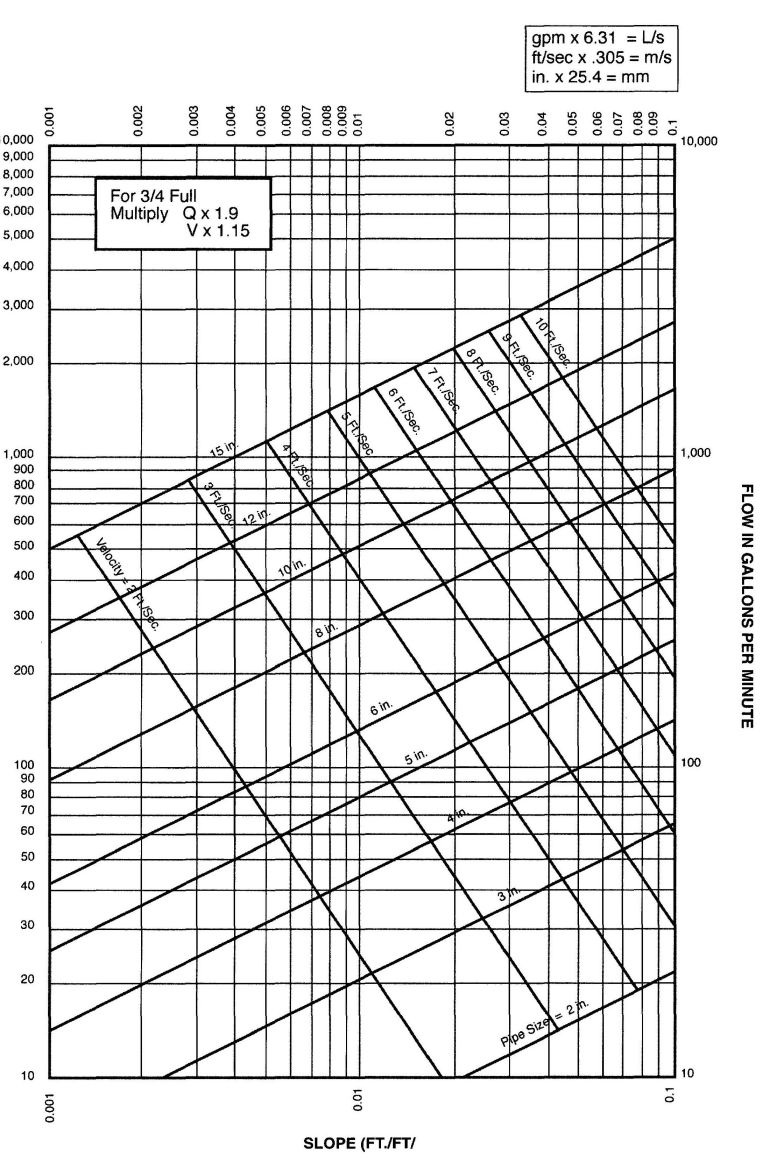
FLOW IN PARTLY FILLED (ONE-HALF FULL) PIPES
(BASED ON MANNING'S FORMULA WITH n = 0.012)
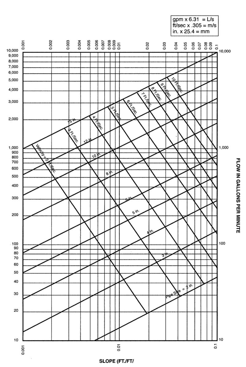
FLOW IN PARTLY FILLED (FULL) PIPES
(BASED ON MANNING'S FORMULA WITH n = 0.012)
For the users of this code, we are including a short explanation and some conversion tables to aid in the conversion of our familiar English units to the forthcoming SI units.
This is written with the code users in mind, and will detail only those measurements used in everyday work and calculations. For the scientific units, we recommend the use of ANSI Z210.1, "Metric Practice Guide.".
Our present system of measuring involves the three dimensions of force, length and time. The SI units involve mass, length, and time. The change of force to mass has meaning in scientific and engineering work, but for practical use in ordinary construction, we will show kilogram to pounds conversion values, although an exact conversion would be pounds force divided by the acceleration due to gravity to mass units.
In the same manner, the SI units for temperature expressed in Kelvins and based on absolute zero will be given as degrees Celsius, which is the more familiar and practical Centigrade degrees.
The SI system measures angles in radians where there are 2 pi radians in a circle, but using a 1.5708 bend to change from a vertical stack to a horizontal house drain is not as easy as calling out a 1/4 bend or an ell for water piping.
The foregoing notes are intended to show that in making conversions from one unit system to another, a little common sense must be used and the degree of accuracy needed to do the job at hand.
The following tables are set up using this approach and using the preferred SI units.
When the plumbing industry, including plumbers, suppliers, and manufacturers, actually begins the metric conversion program, it will undoubtedly follow the guidelines of committees selected from all phases of the construction industry as set up under the American National Metric Council.
The final preferred units used will be those that apply to our industry and will be of the magnitude to simplify and ease job calculations and avoid confusion and ambiguity.
The conversion looks complex and confusing, but when the metric system was first proposed in France, an attempt was made to include a ten-hour day, a ten-day week, and ten months to the year, but cooler heads prevailed and our time still follows the sun and seasons. Likewise, assigning new units or numbers to the quantities we must work with cannot change the basic hydraulic principles that plumbers have worked with throughout history.
Information on conversion factors is provided by ANSI, the American National Metric Council, and the Division of Designatronics, Inc.
© 2009 International Association of Plumbing and Mechanical Officials. All rights reserved.
The copyright in this index is separate and distinct from the copyright in the document that it indexes. The licensing provisions set forth for the document are not applicable to this index. This index may not be reproduced in whole or in part by any means without the express written permission of IAPMO.
Abandoned cesspools, grease interceptors, seepage pits, septic tanks, and sewers 722.0, 1014.3.7, Appendix K
Absorption area, capacity of 1608A.0, Appendix K
Access panels 318.5, 404.2, 414.1, 509.1
Accessible, definition 203.0
Accessibility of:
Chemical waste system 811.0
Cleanouts 707.8, 707.13, 719.5
Drips 1211.8
Fixtures for inspection, repairs, and cleaning 407.1
Floor drain traps 1006.0
Gas meters 1209.6
Gas pressure regulators 1209.7
Grease interceptors 1014.0
Industrial interceptors and separators 1009.5
Receptors 804.1
Regulator and relief valves 608.2
Septic tanks Appendix K
Shutoff and control valves 605.6, 1211.11
Slip joints 404.2
Sump 810.3
Valves, gas 1211.11
Valves, water 605.0
Water heaters 505.3
Acrylonitrile-butadiene-styrene (ABS) 203.0, 311.8, 316.1.6, 316.3.1, 408.4.1 701.1.2, 705.2.5, 707.1, 903.1.2, 903.1.3, 1003.1, 1611A.3, Table 3-2, Appendix K
Additions 101.4.1, 101.5.1
Additives, packing, prohibited 705.1.5
Advance notice for inspections 103.5.4.1
Airbreak:
Definition 203.0
Required 801.1
Airgap:
Definition 203.0
Method 416.2, 603.2.1, 603.4.5, 603.4.12, 603.4.18, 603.4.22, 610.13, Table 6-2, Table 6-3
Required 603.3.5, 603.3.7, 603.4.9, 603.4.13, 611.2, 801.1, 806.0, 807.4
Air intakes, vent termination near 906.2
Air tank, for sumps 710.11
Air tests:
Gas piping system 1214.0
Water piping system 103.5.3.3
Alterations and repairs:
Deviations allowed 101.4.1.1.1, 301.1.4
Gas piping 1214.1.3, 1214.5.3
Alternate materials, design, and methods 1.2.2, 301.2
Anchors and hangers see Supports, 221.0
Appliance:
Connectors 1212.0
Direct-vent 502.7, 510.2.5, 512.0
Gas, demand requirements 1216.0, Table 12-1
In attics 509.4
Indirect waste type 806.0, 807.0
Roofs 509.0
Venting 510.0
Application for permit 103.2
Approval required:
Appliances, fixtures 301.0, 406.0, 508.0, 610.0
Backflow preventers 603.1
Ballcocks 603.4.2
Cesspool Appendix K
Chemical waste system 811.0
Chimneys 504.1
Combination waste and vent system 910.0, Appendix B
Completed plumbing work 103.5.1
Devices 301.1, 603.1
Flue, vents 510.2
Grease interceptor 1014.0
Indirect waste receptors 807.0
Industrial interceptors and separators 1009.2
Materials, specifications, standards 301.0, 701.0
Plans 101.3
Seepage pit Appendix K
Septic tank and disposal system Appendix K
Special fixtures 406.0
Vacuum breakers 603.0, 603.2.2
Vents 504.1
Water heaters, gas 504.0, 505.0
Water heaters, oil 504.0, 506.0
Water supply system 602.4, 603.1
Approved, definition 203.0
Approved testing agency, definition 203.0
Area drain, definition 203.0
Asbestos cement sewer pipe joint 705.1.4
Aspirators 203.0, 603.4.9
Attachment, vertical piping 314.0
Authority Having Jurisdiction, definition 203.0
Authority to:
Disconnect gas 1207.0
Render gas service 1206.0
Automatic:
Flushing tanks 410.2
Flushometer valves 410.3
Interceptors 1017.1
Siphon, septic tank Appendix K
Auto wash racks 1011.0
Backfilling 315.0
Backflow 204.0, 603.0, 603.1
Backflow connection 204.0, 603.0
Backflow preventer see Cross-Connections
Backflow prevention assemblies or devices 602.2, 602.3, 603.0, 603.2, 603.3, Table 6-2
Back-pressure backflow 204.0, 603.3.5, 603.4.6.2, 603.4.8
Back-siphonage see Cross-Connections
Back-siphonage of traps, protection 1002.1
Back-to-back fixtures 704.2
Backwater valve 204.0, 710.1, 1006.0
Ballcocks 603.4.2, Table 6-2
Baptistries 406.1
Bathroom Group, definition 204.0
Bathroom, Half 204.0
Bathtub, prohibited type 405.0
Bathtubs and whirlpool bathtubs 414.0
Bell traps, prohibited 1004.0
Benching of trenches 315.0, 720.0
Bidets 407.5, 416.0
Blow off condensers 810.1, Table 8-1
Boiler blowoff:
Definition 204.0
Prohibited discharge 810.1
Bolts, noncorrosive 407.4
Bottle traps 1004.0
Bottling establishments 1013.0
Bowl wax or gaskets 316.3
Branch, definition 204.0
Branch, fixture, definition 204.0
Branch, horizontal, definition 204.0
Branch vent, definition 204.0
Brass connections, ground joint 705.3.3
Brass pipe 604.0, 705.2.3, 707.1, 903.1, 1209.5.2.3, Tables 6-4, 7-1
Brazing or welding joints 310.2, 316.1.7, 606.1.3, 606.2.1
Btu rating, gas appliances 1209.4.2
Building, definition 204.0
Building drain (sanitary)
Definition 204.0
Size of 703.0
Building drain (storm), definition 204.0
Buildings over sewer 101.4.1.1.2
Building sewer Chapter 7, Part II
Cleanouts 719.0
Combined, definition 204.0
Damage to 306.0
Definition 204.0
Distance from building and below ground 313.3, 720.0
Grade and support of 718.0
Industrial wastes 307.0
Location of 308.0, 313.0, 718.0, 721.0, Table 7-7
Material of 715.0
Required 305.0, 713.0
Sanitary, definition 204.0
Size of 717.0
Storm, definition 204.0
Testing of 723.0
Water pipe in trench 720.0
Building sewers and drains, existing 101.4.1.1.2
Building subdrains 204.0, 1101.6
Building supply, definition 204.0
Burned lead joints 705.1.3
Burred ends 310.3, 609.1, 701.2.1, 1209.5.5
Bushings, solder 701.4.2, Table 7-2(b)
California Administration Chapter 1
Capacity of:
Disposal field Appendix K
Seepage pits Appendix K
Water closet tanks 402.0
Cast-iron soil pipe and fittings:
Joints and connections 316.1.5, 705.1.6, 705.1.7, 705.1.8,705.2
Support of 314.0
Caulked joints 705.1.1
Caulking ferrules 701.4.1, 705.2.4, Table 7-2(a)
Cement mortar joints, prohibited 705.1.2
Certificate of final approval 103.5.6.3, 1205.0
Certification by:
Backflow assembly testers 205.0, 603.1
Medical gas certifiers 1328.1.1
Medical gas installers 1302.2, 1311.3
Medical gas systems 1311.2, 1328.0
Pipe welder, definition 225.0
Cesspool Appendix K
Abandoned 722.0
Connections to sewer prohibited 714.3
Definition 205.0
Distance from lot line, building, surface Table K-1
Must be on same lot as building 308.0
Change in direction of drainage piping 706.0
Change in direction of gas piping 1211.7
Check valves:
In gas systems 1209.8.2
In water systems 603.2, 608.3, Table 6-2
Chemical toilet, prohibited 405.3
Chemical waste 205.0, 811.0
Circuit venting Appendix L
Clarifier 205.0, 1009.0
Clay, vitrified 701.1.3
Joints and connections 705.2.1
Cleanout plugs or caps 707.1–3, 707.13
Cleanouts 707.0, 710.1, 719.0, 1101.12
Clearance for:
Water heaters 505.3.1, 505.3.2
Water heater vents 510.0
Clear water waste, definition 205.0
Clinic sink 205.0, 410.1, Tables 4-1, 4-2
Closet bends 311.3, 311.5, 316.3.2, 316.4.2
Maximum length Table 10-1
Closet rings 316.3.2, 408.4
Closet screw bolts 407.3
Clothes washer stand pipe 804.1
Code:
Definition 205.0
Validity of 103.8
Collection centers and facilities 601.7, 725.0, 1010.2
Combination waste and vent system 205.0, 910.0, Appendix B
Combustible material, definition 502.6
Combustible piping installations 1505.0
Combustion air 507.0
Commissaries serving mobile food preparation units 205.0, 412.9
Common 205.0, 905.6
Common vent, gas 510.6.4.1
Compartments for:
Water heaters 505.1
Compression joints 316.1.5, 606.2.1
Concealed slip joints 404.2
Concealing of work prohibited before inspection 103.5.1.1, 103.5.1.3, 103.5.1.4, 1204.0
Condensers and sumps 810.0
Conductors 1102.1, 1104.0, 1106.0
Connection:
At septic tank Appendix K
Pressure drainage piping 805.0
To plumbing system, required 304.0
To sewer, required 305.0, 713.0
Unlawful 602.0
Water heater 604.13.2
Connector, gas 1212.0
Connector, vent 510.10, 510.11
Construction, existing 101.4.1.3
Contamination 205.0, 601.6, 601.9.1, 603.0, 603.4.5, 609.9.4, Table 6-2
Continuous vent, definition 205.0
Continuous waste:
Definition 205.0
Fittings 404.4
Materials 404.3
Multiple fixtures 1001.0
Control, shutoff valves 605.0, 1211.11, 1212.5
Cooling units:
Drains 801.2
Potable water waste pipes 808.0
Cooling water, connection permitted 808.0
Copper and lead pans 411.8
Copper pipe or tubing:
Connection to screwed pipe 316.2.1
Fittings for 604.1, 701.0, 903.0, 1209.5.8.4
Installation 609.1
Gas 1209.5.2.3, 1209.5.3.2
Joints and connections 606.2.1
Location and use of 604.0, 701.1.4, 811.1, 903.2
Marking of 604.3
Quality and weight of material 604.2, 701.1.4
Support of 314.0
Corrections 103.5.6.1—2
Corrosion, protection from 313.4, 609.3, 612.4, 1211.1.3
Cosmetology 412.7
Cosmetology establishments 412.8, 601.5
Cover plate 707.8
Covered multifamily dwellings, definition 205.0
CPVC—chlorinated poly (vinyl chloride) 205.0, 316.1.6, 604.1.1, Tables 3-2, 6-4
Critical level 205.0, 603.4.5
Cross-connections see Backflow
Approval of preventive devices 601.0–603.0
Backflow preventers 602.0–603.0
Back siphonage 405.1, 1002.1
Control 601.0–603.0
Critical level 603.4.5
Definition 205.0
Prohibited 601.0–603.0
Vacuum breakers 416.2, 601.2.3, 603.2.2, 603.2.6, 603.3.6, 603.3.5, 603.4
Crosslinked polyethylene (PEX) 218.0, 604.11, Tables 3-2, 6-4
Crosslinked polyethylene-aluminum-crosslinked polyethylene (PEX-AL-PEX) 218.0, 604.13 Tables 3-2, 6-4
Cutting of structural members 313.2, 313.11
Damage to drainage and sewer systems 306.0, 714.0
Dangerous or insanitary plumbing 101.5.2
Defective material, gas 1209.5.5, 1207.1, 1214.4
Defective systems, testing of 103.5.5.1
Definition of terms Chapter 2, 502.0, 1203.0
Demand, gas appliance 1209.4.2
Department, definition 206.0
Department Having Jurisdiction, definition 206.0
Design Flood Elevation 206.0, 301.3.1
Detrimental wastes 307.0, 1012.0
Developed length:
Definition 206.0
Trap arm 1002.0, Table 10-1
Dialysis water-distribution systems 613.0
Diameter, definition 206.0
Dielectric insulator 508.1
Dielectric unions 316.2.4
Direct connection of water piping to sewer 602.0, 609.2
Direct vent water heater 502.7, 505.1, 510.2.5, 512.0
Direction, change of 706.0, 719.1
Discharge capacity, fixture 702.2, 710.3
Discharge piping 710.12.1, 710.13.2
Dishwasher connection, domestic 807.4
Disposal fields for graywater 1611A.3
Disposal fields for septic tanks Table K-1, Appendix K
Disposal of:
Food waste 404.4, 714.4, 1001.3, 1014.1.3
Liquid waste 303.0
Distance of trap from vent 1002.2, Table 10-1
Distribution boxes, disposal fields Appendix K
Domestic hot-water distribution systems 612.0, Table 6-9
Domestic sewage, definition 206.0
Doors, shower 411.6
Dosing tanks Appendix K
Double traps, prohibited 1004.0
Downspout, definition 206.0
Drain:
Areaway 1101.7
Building, definition 204.0
Building subdrain 1101.6
Definition 206.0
Fixture, definition 208.0
Floor 311.10, 411.0, 1006.0
House, definition 210.0
Roof 1105.0
Sub-drains (showers) 411.8
Subsoil 1101.5
Window areaway 1101.8
Drainage:
Below curb and main sewer level 710.0
By gravity required 709.0
Change in direction see Change in direction, drainage
Connection to sump 710.2, 710.7
Connection to sewer or private disposal system 305.0, 713.0
Damage to 306.0, 714.0
Defective 103.5.5.1
Durham or recessed screwed fittings 701.2, 701.2.1
Fittings, material 701.2
Grade or fall 708.0, 718.0
Indirect wastes Chapter 8
Length between trap and vent 1002.2, Table 10-1
Material of 301.0, 701.0, 811.1
Piping 311.9
Protection of 313.0
Roof 1101.11
Sizing of piping 703.0
Steam and hot water 810.0
Storm Chapter 11, Appendix D
Support 314.0, 718.0
Waste and vent Table 7-5
Drainage and plumbing, general 726.0, 1010.4
Drinking fountains 405.1, 406.5, 809.0
Drum traps 1004.0
Durham system, definition 206.0
Earthquake-actuated gas shutoff valves 1211.18
Easements for sewers 721.2
Effective opening 207.0, Table 6-3
Ejectors 710.2, 710.9, 710.11
Emergency sanitary drainage 727.0
Emergency water supply 614.4
Employee lavatories in food establishments 412.10
Enforcing agency, definition 207.0
Example, illustrating use of gas tables Figure 12-2
Excavations 315.0, 1204.2
Excessive water pressure 608.2
Existing work 101.4.1.3, 207.0, 301.1.4
Expansion joints 705.3.2
Expansion of pipe, provision for 313.2
Expansion tanks 608.2, 608.3
Faucets 402.1, 415.0, 601.3
Fees 103.4, Table 1-1
Ferrules, caulking 701.4, 705.3.3, Table 7-2(a)
Fill, for building sewers 718.0
Final inspection, certificate 103.5.6.3, 1205.0
Fittings:
Cleanout 707.0, 719.0, Table 7-6
Drainage 701.2
Gas piping 1209.5.4, 1209.5.8, 1209.5.9
Inlet, for fixture connections 704.1
Material of 604.0, 710.4, 1209.5
Prohibited 311.0, 604.10, 1209.5.2.4
Screwed 311.8
Threaded 311.8
Water piping 604.1
Fixture:
Branch, definition 208.0
Connections 704.0
Drain, definition 208.0
Flanged connection 316.3
Future 417.0
Supply 208.0, 601.1, 610.0
Unit 208.0, 702.0
Unit flow rate 610.3, 702.0
Fixtures see Plumbing Fixtures
Flagpoling of vents 906.3
Flammable vapor or fumes, definition 208.0
Flanges 316.3, 408.4, 1209.5.10
Flared joints 316.1.4, 606.1.1, 705.3.3
Flashing 313.8, 510.6.1, 906.5
Flood hazard area, definition 208.0
Flood hazard areas subject to high-velocity wave action 208.0, 301.3.2
Flood hazard resistance 301.3
General 301.3.1
Flood level 208.0, 807.4
Flood-level rim 208.0, 603.3.5, 905.3, 909.0
Flooded, definition 208.0
Floor drains 411.0, 704.3
Backwater valve required 1006.0
Trap location and type 411.3, 1006.0
Trap seal (primers) 1007.0
Floor flanges see Flanges
Floors, under shower compartments 411.5, 411.9
Flow rates, in fixture units 610.3, 702.0
Flue collar 502.8, 510.0, 511.0
Flush tanks 208.0, 410.1, 410.2, 410.4, 410.5, 601.0
Flush valves, definition 208.0
Flushometer tank 208.0, 410.1, 603.4.3, 610.11
Flushometer valve 208.0, 410.1, 410.3 601.0, 603.4.1, 610.10, Table 6-5, Table 6-7
Flux, solder 316.1.3
FOG disposal system 1015.0
Food establishment, definition 208.0
Food-handling equipment 801.2
Food waste disposal unit 404.4, 714.4, 1014.1.3
Freezing, protection of pipes 313.6, 609.1
Frost or snowclosure 906.7
Gang or group showers 209.0, 411.9, 418.0
Garbage grinder see Food Waste Disposal Unit
Gas Chapter 12
Appliance connectors 1203.1, 1212.1, 1212.3, 1212.4
Appliance demand 1209.4.2, Table 12-1
Authority to disconnect 1207.0
Authority to render service 1206.0
Back pressure protection 1209.8
Capping or plugging outlets required 1207.3
Connectors 1212.1, 1212.3, 1212.4
Definition 1203.3
Disconnecting appliances 1207.0
General 1202.0
Hourly volume, rating 1216.2
Inspection 103.5, 1204.0
Installation of 1202.0, 1211.0
Leaks 1214.4, 1214.5
Liquefied Petroleum 1201.0, 1203.7, 1211.5.2, 1213.0
Materials 1209.5
Meters 1209.6
Piping system, definition 1203.5
Plans required 101.3
Service piping, definition 1203.10
Temporary use of 1208.0
Test 1214.0
Underground piping 1211.1
Utility supplying 1205.3
Venting 1209.7.5
Gas piping:
Access to meter 1209.6.2
Concealed 1211.3
Defects, cracks, splits, prohibited 310.2, 1209.5.5
Definition 1203.4
Drips and sediment traps 1211.8, 1212.7
Electrical bonding and grounding 1211.15
Inspection and testing 1204.0, 1214.0
Installation 1211.0
Interconnections 1209.3, 1215.0
Joints 1209.5
Materials 1209.5
Pressure regulator 1209.7
Purging 1214.6
Quick-disconnect devices 1212.6
Required gas supply 1216.0
Sizing 1209.4, 1216.0, 1217.0, Tables 12-8 to 12-41
Supports 1211.2.6, Table 12-3
Unions 1211.3.2
Gas water heater:
Approval requirements 501.0
Clearances 505.3
Combustion air required 507.0
Definition 502.15
Direct vent 502.7, 505.1, 510.2.5, 512.0
Draft hoods 510.12
Inspections 504.0
Location 505.1
Oil burning or other 506.0
Permits required 503.0
Pressure-relief valves 505.4, 505.6, 506.2, 608.0
Protection 505.0, 506.0
Vent required 510.2.1
Gas water heater vent:
Approved type required 510.6
Common vent 510.10.4.2
Connector 510.10
Damper prohibited 510.13
Definitions 502.0
Draft hoods 510.12
Engineered system 510.10.9.2
Existing masonry chimneys 510.5.4
Hood or cap 510.6.2
Inspections 504.0
Material 510.10.2
Mechanical draft systems 510.3.4
Obstructions 510.15
Required 510.2.1
Size of 510.6.3, 511.0
Support 510.6.5, 510.7.6
Termination 510.6.2
Grade:
Building sewer 718.0
Definition 209.0
Horizontal drainage 708.0
Gravity drainage required 709.0
Gravity supply tanks 607.0
Graywater systems Chapter 16A, Appendix G
Absorption capacity 1608A.0
Definitions 1602A.0
Discharge 1606A.0
Drawings and specifications 1604A.0
General 1601A.0
Inspection and testing 1605A.0
Irrigation, disposal field, and mulch basin construction 1607A.0, 1611A.0
Permit 1603A.0
Special provisions 1612A.0
System requirements 1603A.1
Tank Construction 1609A.0
Grease interceptors 1014.0
Definition 209.0
Design and construction 1014.2.1, 1014.3.3
Effluent sampling 1014.3.5.1
Gravity 1014.3
Hydromechanical 1014.2
Location 1014.3.4
Maintenance 1014.3.4.4
Required 1014.1
Sizing 1014.2.2, 1014.3.6 Tables 10-2, 10-3
Venting 1014.1.1, 1014.2.3
Grinder pump 710.12
Ground joint connections 705.3.3
Grounding 604.8, 1211.15
Handwashing fixture, definition 210.0
Hangers see Supports
Harmful waste see Waste, detrimental, and harmful
Health and safety 101.2, 101.5.2
Heat exchangers 603.4.4
High hazard 210.0, Table 6-2
Horizontal branch 210.0, 703.0
Horizontal pipe, definition 210.0
Horizontal-to-horizontal drainage fittings 706.3
Horizontal-to-vertical drainage fittings 706.2
Horizontal vent pipes Table 7-5
Horse meat and per food establishments 601.9, 1010.3
Hose connections 603.2.3, 1212.0
Hot-mopped shower pans see Shower pans
Hot water boiler 506.2, 506.4.2
Hot water pipe sizing 610.0
House drain see Building sewer
House sewer see Building sewer
Identification:
Copper tubing 604.3
Gas piping 1209.6.5, 1209.7.7
Piping, fittings, traps, and fixtures 301.1.2, 1003.1
Required 301.0
Water lines, non-potable, and potable 601.2, 614.0
Increasers 317.0
Independent system of sewers 312.0
Indirect waste:
Accessibility 804.1
Appliances 807.0
Condensers and sumps 810.2
Cooling water 808.0
Definition 211.0
Drinking fountains 809.0
Food-handling equipment 801.2
Sterilizing equipment 801.5, 806.0
Indirect waste piping:
Airbreak or airgap 801.0, 806.0
Approval required 802.0
Cleanouts 803.0
Connections 801.1, 805.0
Definition 211.0
Installation of 313.6, 802.0, 803.0, 810.0
Maximum length 803.0
Required 801.0
Size of 803.0
Steam and hot water 810.0
Vents 803.0
Indirect waste receptors:
Approval required 802.0
For clothes washers 804.0
Prohibited location 804.1
Required water supply 601.1, 1007.0
Size of 801.2.1, 814.2
Individual vent 211.0, 1014.1.1, Table 7-5
Industrial interceptors and separators 1009.0
Industrial wastes:
Approval required 811.1, 1009.2
Definition 211.0
Disposal 307.1, 811.1
Materials 811.2, 903.2.3, 1009.2
Pretreatment 307.0, 811.1
Inlet fittings for fixture connections 704.1-2, 706.2, 710.9
Insanitary:
Additions, alterations, or repairs 101.5.1
Construction 101.4.1.3
Definition 211.0
Inspection and testing:
Abandoned cesspools, grease interceptors, seepage pits, septic tanks, and sewers 722.0, 1014.3.7, Appendix K
Advance notice for 103.5.4.1, 1204.0
Building sewer 723.0
Certificate 103.5.6.3, 1205.0
Chimneys and vents 504.0
Concealment of work, prohibited before inspection 103.5.1.1, 103.5.1.3, 1204.0
Drainage 710.6, 710.10
Disposal fields Appendix K
Final 103.5.6.3, 504.2, 1204.3.2
Gas piping, rough and final 1204.3
Labor and material for 103.5.4.2
Water heaters 504.2
Water piping 103.5.1.1
Inspector see Authority Having Jurisdiction
Installation of:
Building sewer: 715.0, 717.0, 718.0
Cleanouts 707.0, 719.0, Table 7-6
Devices to prevent cross-connections 602.0, 603.0
Drainage piping system Chapter 7
Fixtures 407.1
Floor drains and shower stalls 411.0
Gas piping systems 1211.0
Overflows 403.0
Urinals 402.3, 407.0, 409.0
Vents Chapter 9
Water piping system 609.0, 610.0, Appendix A
Integral traps 1001.1, Table 7-3 pn,
Intercepting hoppers or sink see Receptors
Interceptors:
Abandoned 1014.3.7
Auto wash rack 1011.0
Cleanouts, location 707.8
Definition 211.0
Grease 1014.0
Industrial 1009.0
Location 1009.5
Maintenance 101.4.1.2, 1009.6
Oil and flammable liquid 1017.0
Packing establishments 1010.0
Required 1009.1
Sand 1016.0
Slaughterhouse 1010.0
Vent 902.1
Intermixing of metals prohibited 311.6, 604.1
Invert, definition 211.0
Iron pipe size (IPS) pipe 302.0
Irrigation field 1611A.2
Island fixture, venting 909.0
Joints and connections:
Additives prohibited 705.1.5
Asbestos cement sewer pipe 705.1.4
Brazed 212.0, 316.1.7, 609.3.2, 1211.3.2
Burned lead 705.1.3
Cast iron 705.1, 705.2.2-4
Caulked 705.1.1
Cement mortar, prohibited 705.1.2
Compounds, thread lubricants 316.1.1, 1209.5.7
Compression 316.1.5, 606.2.1
Copper to screwpipe 316.2.1
Copper tube 316.2.1, 606.2.1
Elastomeric gasketed 705.1.7
Expansion 705.3.2
Ferrule 705.3.3
Fixture 316.3, 407.2, 704.0
Flared 316.1.4, 606.1.1, 705.3.3
Flexible 316.1.5
Floor-mounted 316.3, 704.0
Gas and watertight 103.5.3.4
Gas piping 1209.5
Ground joint 705.3.3
Heat fusion weld joints 316.1.11
Hubless cast iron 705.1.9
Increasers and reducers 317.0
Lead 316.1.2, 705.1.3, 705.2.4
Mechanical 606.1.2
Mechanically formed tee 606.1.3
Molded rubber coupling 705.1.6
Plastic piping, joints, and fittings 1209.5.9
Plastic vent joints 510.4.3
Pressed 316.1.9
Pressure-lock-type 316.1.8
Prohibited fittings and practices 311.0, 316.4, 317.0
Push-fit fitting 316.1.10
Rubber ring 705.1.7
Screwed 311.8, 316.1.1
Shield coupling 705.1.8
Slip 404.2, 606.2.3, 705.3.1, 1003.2
Soldered or sweat 212.0, 316.1.3
Solvent cement plastic pipe 316.1.6
Special 316.2
Threaded 316.1.1
Tightness 103.5.3.4
Tubing 316.1.3, 316.2.1, 606.2.1, 1209.5.8.2
Union 316.2.2, 609.5, 1211.3.2
Vitrified clay 705.2.1
Welded 225.0, 316.1.7, 705.1.3, 1211.3.2
Wiped 316.1.2
Kitchen sinks, prohibited types 405.3
Labeled 214.0, 301.1.1
Labor for tests 103.5.4.2
Laboratories, chemical 811.8
Laundry tubs 1001.2, 1001.3, 1003.1
Lavatories 214.0, 413.1
Lavatories in sets, definition 214.0, 413.1
Lawn sprinklers 603.4.6
Lead:
Closet rings 408.4
Sheet 401.2, 701.3
Shower receptor 411.8
Lead joints see Joints, Lead and Connections
Lead traps and bends 701.3
Leaders 214.0, 1102.2, 1103.0, 1104.0, 1106.0
Leaks, gas piping 1214.4, 1214.5
Length:
Connector 604.12
Developed, definition 206.0
Drainage piping 703.0, Table 7-5
Gas piping 1217.0
Vent piping 904.0, Table 7-5
Water piping 610.0
Limited-density owner-built dwelling 214.0, 604.1.1
Liquefied petroleum gas (LPG) 1201.0, 1203.7, 1211.5.2, 1213.0
Liquid waste:
Definition 214.0
Disposal of 303.0
Listed 214.0, 301.1.1
Listing agency 214.0, 301.1.1
Loading, fixture unit Tables 6-5, 7-3, 7-4
Local authority to approve CPVC pipe, residential 604.1.1
Location of:
Backwater valve 710.1, 710.4, 710.6, 1006.0
Fixtures 309.0
Gas meters 1209.6
Gas valves 1209.8.2, 1209.10, 1210.0, 1211.2.4, 1211.11, 1212.5
Industrial interceptors and separators 1009.0
Plumbing or sewer on lot 308.0, 721.1, Table 7-7
Pressure-relief, regulator, or check valves 608.0, 1209.7.3
Private sewage disposal system Appendix K
Secondary protection, water heaters 506.2
Shutoff valves 505.6, 605.0, 710.12.1, 710.13.2, 1211.11, 1212.5
Temperature relief valves 505.6, 608.3
Vent terminals 510.3.4.6, 510.8.2, 510.8.3, 906.0
Water heaters 505.1, 508.0
Lot, definition 214.0
Lot line, termination of vents from 906.2
Low hazard 214.0, Table 6-2
Low VOC cement, definition 214.0
Low VOC one-step cement 214.0, 316.1.6
Low VOC primer 214.0, 316.1.6
Lubricants, thread 316.1.1, 1209.5.7
Macerating toilet system 215.0, 710.13
Main, definition 215.0
Maintenance 101.4.1.2, 1007.0, 1009.6
Material:
Alternate 301.2, 406.3
Approval required 301.1.1
Backwater and gate valves 605.4, 710.4, 710.6
Building drain 701.0, Table 7-1
Building sewer 715.0, Table 7-1
Cesspool Appendix K
Cleanouts 707.1, 707.2
Condensers or intercepting tanks 810.2
Drainage systems 701.0, Table 7-1
Fittings 301.0, 311.0, 1209.5
Gas piping 1209.5
Marking of 301.1.2, 604.3, 710.6, 716.0
Medical gas and vacuum 1316.0
Potable water piping 604.0, Appendix A
Septic tank Appendix K
Showers 411.5
Soil and waste pipes 701.0, Table 7-1
Specifications, standards 301.1.3
Sumps or receiving tanks 710.8, 810.2
Thread lubricants 316.1.1, 1209.5.7
Traps 1003.1
Valves and fittings 605.1
Vents 701.0, 903.0, Table 7-1
May, definition 215.0
Meat and poultry processing plants 601.6, 717.1, 724.0, 1010.1
Meat packing and slaughterhouses 1010.0
Medical gas and vacuum systems Chapter 13
Alarms 1324.0
Cleaning 1317.0
Definitions 320.0, 1310.0
General requirements 1311.0
Installation requirements 1302.0, 1318.0
Joints 1319.0
Labeling 1323.0
Materials 1316.0
Pipe sizing 1314.0
System certification 1328.0
Testing 1327.0
Valves 1320.0
Metals, intermixing prohibited 311.6, 604.1
Meters, gas 1209.6
Meters, water 610.0, Appendix A
Minimum standards 301.0
Natural gas, specific gravity 1216.0
Nipples, soldering 316.1.2
Nonmetallic gas hose connectors 1212.3
Nonwater supplied urinals (waterless urinals) 216.0, 402.3.3
Nonwater urinals 402.3.4
Non-combustible piping installations 1506.0
Non-corrosive bolts 407.3, 407.4
Non-potable water piping 603.4.11, 610.13(6)
Identification 601.2, 614.0
Non-potable water reuse systems Chapter 16A
Notching 313.2
Notice of inspection 103.5.4.1, 1204.0
Nuisance 101.4.1.3, 101.5.2, 216.0, 713.6
Obstructions to flow 311.5, 316.4, 510.15
Offset 217.0, 510.6.1.1, 511.1.2, 511.1.6, 511.2.5, 511.2.16, 511.2.19, 706.4, 905.3, 910.5, 1209.11.1
Oil and flammable interceptors 217.0, 1017.0
One-and two-family dwellings 301.5
Opening, effective, definition 207.0
Open trench work 315.3
Overflow:
Gravity supply tank 607.0
Plumbing fixture 403.0
Rim, flood-level rim 208.0, 403.0
Oxygen, fuel gas 1209.8.1, 1214.1.7
Packing additives prohibited 705.1.5
Packing establishments, grease interceptors required 1010.0
Penalties 102.3.2, 103.5.6.1
Percolation tests Appendix K
Permit, required 103.1.1, 103.4.4.1, 103.5.1, 503.0
Photographic rooms, waste from 811.8
Piping:
Building, adjacent to 313.3
Building supply size 610.0
Cleanout 707.0, 719.0
Compounds, thread lubricants 316.1.1, 1209.5.7
Diameter, definition 206.0
Drainage, horizontal, grade of 708.0
Drainage piping, size of 703.0
Embedded in masonry or concrete 313.2
Gas, definition of 1203.0
Gas, size of 1216.0, 1217.0
Hangers and supports 314.0, 1211.2.6, Table 12-3
Horizontal , definition 210.0
Hot water, size of 610.0
Improper location 309.0
Increasers and reducers 317.0
Interconnection of gas systems 1215.0
Joints 103.5.3.4, 316.0, 606.0, 705.0, 1209.5
Non-potable water 603.4.11
Protection from freezing 313.6, 1211.1.4
Protection required 313.0, 315.4, 609.3, 1211.1
Protectively coated 313.5
Reaming 310.3, 609.1, 701.2.1, 903.3, 1209.5.5
Size of; see Diameter 302.0, 610.0, 703.0, 904.0, 1216.0, 1217.0
Soil, definition 221.0
Special wastes 221.0, Chapter 8
Threads 311.8, 316.1.1, 701.2.2, 1209.5.7
Tube, forming 609.1
Underground 316.2.2, 604.2, 701.1.1, 903.1.1, 1211.1
Vent 224.0, Chapter 9
Vertical 224.0, Table 3-2, Chapters 7, 9
Waste 225.0, Chapters 7, 8
Waste, indirect 211.0, Chapter 8
Water, materials 604.0, Table 6-4
Water, size of 610.0
Water-distributing, definition 225.0
Welder, definition 225.0
Wrapping 609.3.1, 1211.1.3
Pit, seepage 221.0, 722.2, Appendix K
Plans required 101.3
Plastic piping 311.11
Plastic joint solvent cement 316.1.6
Plugs, caps, cleanout 707.1-2
Plugging, fixture outlets 101.4.1.1.3
Plumbing:
Additions and alterations 101.4.1
Appliance, definition 218.0
Appurtenance, definition 218.0
Connected to sewer or private disposal system 304.0, 305.0, 713.2
Defective, test of 103.5.5.1
Definition 218.0
Inspection of 103.5
Official see Authority Having Jurisdiction
Repairs 101.4.1.1
System, definition 218.0
Test required 103.5.3
Uncovered for inspection 103.5.1.4
Plumbing fixtures:
Accessibility 407.1, 407.6
Alternate materials 301.2, 406.3
Back-to-back 704.2
Below curb or sewer level 710.1-2
Clearance from wall, toilet, urinal 407.5
Connections, drainage 316.3, 404.0, 406.1, 704.0
Control valves 605.0
Definition 218.0
Distance from traps 1001.2, 1001.4, 1002.2, Table 10-1
Floor drains and showers 411.0, 1006.0
Improper location of 309.0
Indirect waste 804.0
Installation of 407.0
Island 909.0
Joints 316.0, 407.2
Material of 401.0, 406.2, 406.3, 408.4, 411.5, 411.8, 416.1
Must be connected to sewer 304.0, 305.0
Must be provided with trap 1001.1
Overflows 403.0
Prohibited 311.0, 311.5, 405.0, 910.7
Quality 401.1
Setting 316.3.1, 407.5
Size of waste for 702.0, 703.0, Tables 7-3, 7-5
Special fixtures 406.0
Standards 401.1
Strainers and connections 404.1
Supply and waste connection, access to 404.2
Supply fittings 407.7
Unit equivalent 610.3, 702.0, 703.0, Tables 6-5, 7-3, 7-4
Water supply required 601.0
Pollution 218.0, 601.6, 601.9.1, 603.4.5, Table 6-2
Polyethylene (PE) 218.0, 604.1
Polyethylene-aluminum-polyethylene (PE-AL-PE) 218.0, 604.13, Table 3-2
Polypropylene (PP), definition 218.0, 1003.1
Polyvinyl chloride (PVC) 218.0, 408.4.1, 604.1, 701.1.2, 705.2.5, 707.1 903.1.2, 903.1.3, 1003.1, 1611A.2, 1611A.3
Polyvinylidene flouride (PVDF), definition 218.0
Potable water:
Definition 218.0
Disinfection 609.9
Identification 601.2, 614.0
Protection of 602.0, 603.0
Supply required 601.0
Unlawful connection to 602.0
Pressure drainage connections prohibited 805.0
Pressure, excessive, water 608.2
Pressure losses, water 610.2
Pressure regulator, when required 608.2-6
Pressure, regulator, gas 1209.7
Pressure-relief valve 505.4, 505.6, 506.2, 608.0
Preventer, backflow 204.0, 603.2
Primary settling tank 902.1
Private or private use, definition 218.0
Private sewage:
Capacity of system Appendix K
Construction Appendix K
Disposal system 218.0, Appendix K
General 103.5.1, Appendix K
Location 721.0, Appendix K, Table 7-7
Private sewer, definition 218.0
Private water supply 602.2, 602.4
Prohibited:
Additives, packing 705.1.5
Cement mortar joints 705.1.2
Concealed gas piping 1211.3
Concealment of defects 310.2, 1214.4.3
Concealment of work before inspection 103.5.1.1, 103.5.1.3, 1204.0
Connections, rainwater 306.2
Connections, waste 403.0, 805.0, 806.0
Connections, water 602.0
Copper tubing, use of 903.2.3, 1209.5.2.3
Damage to drainage system 306.1, 313.0
Defective material 103.1.2.1, 1214.4
Direct drainage 603.3.5, 801.2, 810.1
Drinking fountain location 405.1
Fittings 311.0, 316.4
Fixtures 311.5, 405.0
Floor drains 311.10
Food waste disposal, connection to 1001.3, 1014.1.3
Gas piping location 1211.2.5
Gas water heaters in bathroom, bedroom 505.1
Industrial waste disposal 307.0
Joints and connections 316.4, 606.2.2, 705.0
Oxygen 1214.1.7
Pipes in masonry 313.2
Practices 101.4.1.1.2, 310.2, 311.0, 313.2, 313.6, 316.4, 602.0, 714.0
Receptors, location of 804.1
Soldered joints 316.1.3.1
Traps 1004.0
Trough type urinals 405.2
Urinals and water closets on combination waste and vent 910.7
Water piping in drainage or sewer trench 720.0
Property line, termination of vent 906.2
Protection from:
Corrosion 313.1, 313.4, 609.3.1, 1209.5.6
Freezing 313.6
Protection of:
Gas meters 1209.6.4
Piping materials and structures 313.0, 315.4, 1211.1
Potable water supply 603.0
Trap seal 1002.0, 1005.0, 1007.0
Water heaters 505.3–505.6, 506.2
Public, or public use, definition 218.0
Public sewer, definition 218.0
Public shower floors 411.9
Quality and weight of materials, general regulations Chapter 3
Quality of fixtures 401.1
Quick-disconnect device 1212.6
Rain and surface water drains 306.2
Rainwater systems Chapter 11, Appendix D
Rate of flow, fixture unit 610.3, 702.0, Tables 6-5, 7-3
Ratproofing 313.12
Reaming pipes 310.3, 606.1.1, 701.2.1, 1209.5.5
Receiving tank or sump 710.2–3, 710.7–10, 710.13.1
Receptors:
Definition 220.0
Indirect waste 804.0
Shower, shower stalls 411.0
Recessed or durham fittings 206.0, 701.2.1
Recommended loadings, sewage disposal Appendix K, Table 7-5
Recycled water Chapter 16A
Definitions 1614A.0
Drawings and specifications 1616A.0
General 1613A.0
Identification 1617A.0
Inspection and testing 1620A.0
Installation 1618A.0
Permit 1615A.0
Pipe material 1617A.0
Signs 1619A.0
Sizing 1621A.0
Reducers 317.0
Refrigerators 801.2
Regulators
Gas supply 1209.7
Line pressure, identification 1209.7.7
Relief valves on water supply 608.2-6
Regulators, relief valves on water supply 608.2—6
Relief vent 907.0
Connections 805.0
Definition 220.0
For closed condensers, sumps, interceptors 810.1–3, 1009.4
Remote outlet, definition 220.0
Renderers 601.8
Repairing:
Defective gas pipe, prohibited 1209.5.5
Defective pipe and fittings 101.5.1
Repairs and alterations to plumbing and drainage system 101.4.1.1
Required:
Hot and cold water 601.0
Plans 101.3
Plumbing fixtures 412.0, 412.1.1, Tables 4-1, 4-2, 4-3, 4-4
Sewer connections 305.0
Vents 901.0
Responsible for testing 103.5.4.2
Restaurant, grease interceptor 1014.1
Retesting 103.5.6.2
Rim:
Definition 220.0
Flood level 208.0, 603.3.5, 603.4.9, 905.3, 909.0
Rise:
Horizontal vent 905.3
Vents above fixture 905.3
Riser 220.0, 411.11, 610.1
Roof drains 1105.0
Roof drainage 1101.11
Primary 1101.11.1
Secondary 1101.11.2
Combined 1101.11.2.2.2
Seperate piping 1101.11.2.2.1
Roof gutters 1106.3
Roof supply tanks 607.0
Roof, termination of vents above 510.6.2, 905.4, 906.1, 906.3, 906.5, 906.7
Roughing-in, definition 220.0
Saddle, sleeve, band outlets, prohibited 311.1
Safety and health 101.5.2
Safety devices 505.0, 603.0, 608.0
Sand interceptor 1016.0
Cleanout for 707.7
Construction and size 1016.2
Definition see Interceptor
Design 1009.3
Discharge 1009.7
Location 1009.5
Required 1009.1, 1016.1
Required for steam exhaust or blow off 810.0, Table 8-1
Secondary 902.1
Type of trap 1009.2
Vent, required and not required 901.0, 902.0, 1002.0, 1016.3
Water seals 1009.3
Sanitary tees, permissible use 706.2
Schools of Cosmetology 601.5
Screw joints 316.2.1, 705.2.3
Screw pipe to cast iron 705.2.3
Screw pipe to copper tubing 316.2.1
Scrub sink 221.0, Table 4-2
SDR, definition 221.0
Seal, trap; see Trap, seal 1005.0, 1007.0
Secondary interceptors 902.1
Secondary temperature limiting device 506.2
Seepage lines Appendix K
Seepage pit Appendix K
Abandoned 722.0, Appendix K
Connection to sewer prohibited 714.3
Construction Appendix K
Location 721.0, Table 7-7
Size Appendix K
Soil absorption Appendix K
Self-cleaning traps 1003.1, Table 7-3
Separate plumbing and drainage systems 312.0
Separate venting 811.6, 906.3
Separator 1009.0
Septic tanks 221.0, Appendix K
Abandoned 722.0, Appendix K
Connections to sewer prohibited 714.3
Location of 721.0, Table 7-7
Service, authority to render gas 1206.0
Service piping, gas, definition 1203.10
Setting fixtures 316.3.1, 407.5
Settling tank 902.1
Sewage:
Definition 221.0
Disposal of 303.0, 305.0, 709.0, 713.0, 714.0
Sewage disposal system, private Appendix K
Abandoned 722.0
Construction 715.1
Holding tank 714.5
Location 721.0, Table 7-7
Sewage ejector, definition 221.0
Sewage pump, definition 221.0
Sewers Chapter 7
Abandoned 722.0
Adjacent to walls 715.1, 718.3, Table 7-7
Available 305.2, 713.2, 713.4
Building, material of 701.0, 715.1, Table 7-1
Building sewer 204.0, Chapter 7
Cleanouts 719.0
Connection to, required 304.0, 305.0, 713.0
Construction of 715.0–719.0
Damage to 306.1, 714.1, 811.1
Depth of 708.0, 718.3
Easements for 721.2
Ejectors 710.2
Existing 101.4.1.1.1–2, 312.0, 705.1.2, 713.6, 715.3
Grade and support of 708.0, 718.0
Independent system required 312.0
Inspection, order of 103.5.1
Installed on made or filled-in ground 718.2
Location 308.0, 313.0, 718.0, 720.0, 721.0, Table 7-7
Materials 101.4.1.1.2, 715.1, 718.3, 720.0, Table 7-1
Mobile home park sewer 215.0
Must be on same lot as building 308.1, 721.1
Pipe joints 705.1
Private sewage disposal system 218.0, 305.1–2, 713.0, 714.0
Public, damage to 306.1, 714.1
Public or public use, definition 218.0
Required 305.0, 713.0
Size of building 710.5, 717.0, Table 7-8
Testing of 101.4.1.1.2, 723.0
Water pipe in trench 720.0
Shall, definition 221.0
Sheet lead 401.2, 411.8, 701.3
Shielded couplings 221.0, 705.1.8
Shock arrester, definition 221.0
Short turn ¼ bend, prohibited 311.5, 706.0
Should, definition 221.0
Shower control valves 418.0
Shower pans 411.8
Shower receptors 411.8
Shower stall or compartment 411.7
Showers, gang or group 209.0, 411.9, Table 7-3
Shutoff valves 505.6, 605.0, 710.12.1, 710.13.2, 1209.10, 1211.11, 1212.5
Single-family dwelling, definition 221.0
Single-stack vent system Appendix L
Sinks:
Clinic 205.0, 410.1, Tables 4-1, 4-2
Connections 404.3, 404.4
Faucets 402.1.2
Island 909.0
Laundry 1001.2. 1001.3, 1003.1, Tables 4-2
Prohibited 405.3
Scrub 221.0, Table 4-2
Special use 406.2, 406.3
Size of:
Building sewer 703.0, 717.0, Tables 7-3, 7-5, 7-8
Cesspool Appendix K
Combination waste and vent piping 910.0, Appendix B
Combustion air vents 506.1, 507.0
Disposal field Appendix K
Drainage piping, minimum 703.0, Tables 7-3, 7-5
Gas piping system 1216.0, 1217.0
Indirect waste pipes 803.0
Leaders, conductors, and storm drains 1106.0
Medical gas and vacuum pipe 1314.0
Pipe cleanout 707.10, Table 7-6
Seepage pit Appendix K
Septic tank Appendix K
Trap 702.1, 910.4, 910.6, 1003.3, 1006.0, Table 7-3
Vent pipes 710.10, 810.1, 904.0, 905.4, 906.0, 908.1.2, 908.2.3, 910.3, Table 7-5
Vent stack 906.0, 907.1, Table 7-5
Water piping 609.0, 610.0
Slaughterhouses 1010.0
Slip joints 316.1.5, 404.2, 705.1.6, 705.1.8–9, 705.3.1, 705.3.3
Slip joints, traps 705.3.1, 1003.2
Slope see Grade
Soil pipe 221.0, 311.2, 311.4, 701.1.6, 705.1.1, 705.1.9, 722.2, 1002.4, Table 7-1
Soil porosity Appendix K
Soil stack, minimum size 703.0
Solder, bushings 316.1.2, 701.4.2, Table 7-2(b)
Solder fluxes 316.1.3
Solder joints 212.0, 310.2, 316.1.2–3, 316.2.1, 316.3.1, 606.2.1, 705.2.4, Table 3-2
Spacing:
Gas risers or meters 1209.2, 1209.6.2
Pipe supports 314.1, 314.7, Table 3-2
Special fixtures 406.0
Special joints 316.2
Special venting 909.0
Special waste pipe see Industrial Waste
Special wastes:
Acid 811.2
Chemical 811.0
Definition 221.0
Industrial 811.0
High temperatures 810.1, Table 8-1
Laundries, bottling works, wash racks 702.0, 711.0, 1012.0, 1013.0
Specific gravity, natural gas 1216.1
Specifications for materials 301.0, Table 14-1
Stack 221.0, 311.4, 705.3.2, 711.0, 906.1, 907.1
Standards for materials 301.0, Table 14-1
Standpipe, clothes washer 804.1
Steam exhaust condenser or blow off 810.0, Table 8-1
Sterile equipment 806.0
Storage tanks:
Gravity 607.0
Hot water 506.2
Storm drain 221.0, 1101.5, 1101.10, 1101.11
Storm sewer, definition 221.0
Strainers and connections 404.0
S-trap prohibited 1004.0
Street main; see Water main 225.0, 610.7, Tables 6-5, 6-6
Structural condition safety 313.2, 313.11
Submittal of plans 101.3, 103.2.1.4, 103.3, 103.4.2-3
Subsoil drains 221.0, 1101.5
Substitute materials 301.2
Subsurface disposal field Appendix K
Suds relief 711.0
Sump:
Boiler room, installation 810.1, 810.3
Building, backwater devices 710.3, 710.4
Building drainage systems below sewer level 710.2
Condensers 810.0, Table 8-1
Construction 810.2
Definition 221.0
Pump connection permitted 710.2-3, 710.5, 710.9, 805.0, Table 7-4
Pump discharges, conversion to fixture units 702.2, 710.3, 710.5, Table 7-4
Sewage 710.0
Vent 710.7, 710.10, 810.1, Table 8-1
Supply:
Control valves, water 605.0
Fittings, fixtures 407.7
Fixture, definition 208.0
Hot water 601.9.3, 601.3, 602.1, 603.3.6
Non-potable water 603.4.11
Pipe, size of 610.0, Tables 6-5, 6-6
Potable water, protection 603.0
Tank, water 607.0, 608.1
Water, quality of, source of 601.1
Supports and hangers 221.0, 314.0, 510.10.10, 609.1, 906.4, 1211.2.6, Tables 3-2, 12-3
Surface water, discharge 307.2, 714.2, 811.1
Surrounding material 407.2
Sweat joints 316.1.3, 316.2.1
Swimming pools, spas, and hot tubs 603.4.22, 813.0
System:
Combination waste and vent 205.0, 910.0, Appendix B
Defective, testing of 103.5.5.1
Dialysis water 603.4.20.1, 613.0
Domestic hot-water distribution for health facilities and clinics 612.0
Drainage 206.0, Chapter 7
Durham, definition 206.0
Engineered vent 911.0
FOG disposal 1015.0
Gas piping, size of 1216.0, 1217.0
Independent 312.0
Medical gas and vacuum Chapter 13
Plumbing, definition 218.0
Pure Water Process 603.4.20
Storm water drainage Chapter 11
Water supply 225.0, 609.0
Tailpiece:
Connection 807.2, 910.5–6
Maximum length of 910.5
Size 404.3
Tanks:
Automatic flushing, urinals 410.2
Boiler blow off; see Condensers and Sumps 810.1, Table 8-1
Flush 208.0, 403.0, 407.4, 410.0, 601.1, Table 7-3
Gravity supply 607.0
Hot water storage 608.3, 608.6, 608.7
Inlet to 603.4.2, 603.4.5, 710.9, 810.1
Material 710.8, 810.2
Primary settling 902.1
Septic see Septic Tank
Water closet 403.0, 405.1, 601.1, 603.4.2–3
Water supply 602.1, 605.2, 607.0, 608.1, 608.3
Water supply, overflow 603.4, 607.0
Temperature-limiting devices 413.1, 414.5, 416.3, 418.0, 505.5
Temperature-relief valves 505.6
Temporary use of gas 1208.0
Termination of vents 510.6.2, 906.0
Testing agency, definition 222.0
Tests:
Advance notice for 103.5.4.1
Air 103.5.3.3, 103.5.5.1, 1214.1.7
Alternate materials, methods 301.2.1
Building sewer 101.4.1.1.2, 103.5.1.3–4, 723.0
Concealing of work prohibited before inspection 103.5.1.1, 103.5.1.3–4, 1204.0
Exceptions 103.5.3.3
Final 103.5.6.3, 712.1, 1204.3.2
Gauges 319.0, 1204.3.2, 1214.3
Labor and material for 103.5.4.2
Precolation Appendix K
Preparation 1214.2
Required 103.5.3
Responsibility for 103.5.4.2
Shower receptors 411.8.1
Storm drainage 1109.0
Testing agency 301.2.1, 610.2
Waived 103.5.3.2
Water supply system 103.5.1.1, 610.2
Thread lubricants 316.1.1, 1209.5.7
Threaded fittings 316.1.1, 316.2.1, 705.2.3, 1209.5.7
Threaded joints 316.1.1, 316.2.1, 705.2.3, 1209.5.7
Three-compartment sinks 1001.2
Toilet room, definition 222.0
Toilets:
Connections 316.4.2
Definition 222.0
Prohibited type 405.1
Trap Chapter 10
Arm 222.0, 1002.2–3, Tables 7-3, 10-1
Definition 222.0
Drum 1004.0
Exceptions for 1001.1–3, 1002.3
Floor drain 1003.1, 1006.0, 1007.0
For sumps, condensers 810.1
For three-compartment sinks or three lavatories 1001.2
From fixture, distance of 1001.4
From vent, distance of 704.2, 1002.2, Table 10-1
Indirect waste 803.0
Industrial interceptors and separators 1009.0
Integral 1001.1
Liquid seal 1005.0
Material of 103.1.2.1, 301.1.1-2, 807.3, 1003.1
Minimum size 702.0, 1003.3, Table 7-3
Prohibited types 1004.0
Protection 1002.1–2
Required 1001.0
Seal 222.0, 911.2, 1005.0, 1007.0
Seal primer 1007.0
Separate for each fixture 1001.1
Size 1003.3, Table 10-1
Slip joints in 705.3.1, 1003.2
Storm drains and leaders 1103.0
Union joint in water seal 316.2.2
Unit loading 702.0, Tables 7-3, 7-5
Vents for 810.1, 901.0, 905.2, 905.5, 908.1.1, 908.2.1, 908.2.2, 909.0, 910.5, 1002.0, Tables 7-5, 10-1
Vent not required 902.0
Weir 905.5, 1001.4, 1002.2, 1002.4
Trenching, excavation, and backfilling 315.0, 718.0, 720.0
Trough urinals, prohibited 405.2
Tubing, copper 316.1.3, 316.2.1, 604.2-3, 606.1.1, 606.2.1, 609.1, 609.3.2, 610.12, 701.1.4, 705.3.3, 903.2, Tables 6-4, 7-1
Tubing, gas connectors 1212.1, 1212.3
Tunneling 315.2
Unconfined space, definition 223.0
Underground:
Combination stop-and-waste valves 603.4.19
Copper tubing 604.2, 701.1.4
Dosing tanks Appendix K
Drainage material 316.2.2, 701.0
Gas piping 1211.1
Vent material 316.2.2, 701.1.4, 903.1.1
Water pipes 609.8, 720.0
Unions:
Couplings, in gas piping 1209.5.8.4, 1209.11.1, 1211.1.3, 1211.3.2, 1212.4
Joint in seal of trap 1003.2
Location 316.2.2, 609.5
Where allowed 316.2.2, 1211.3.2(4)
Unit, fixture 208.0, 610.3, 702.0, Tables 6-5 to 6-7, 7-3
Unit loading of traps 702.0
Unlawful connections 602.0
Unsanitary, definition 223.0
UPC, definition 223.0
Urinals 316.3.1, 402.3, 403.0, 404.1, 405.2, 407.5, 409.0, 601.1, 707.4, 910.7, 1003.1, Tables 6-5, 7-3, 7-5
Use of alternate material 301.2
Use, private, definition 218.0
Use, public, definition 218.0
Vacuum breaker 224.0, 409.0, 416.2, 601.2.3, 603.2.2, 603.2.5, 603.2.6, 603.3.5, 603.4.1, 603.4.5, 603.4.6, 603.4.7, 603.4.9, 603.4.15, 603.4.18, Table 6-2
Vacuum drainage systems Appendix L
Vacuum relief valve 224.0, 608.7
Validity of code 103.7.1, 103.8
Valves:
Accessible 605.8
Backwater 710.1
Check 603.2, 608.3, 1209.8.2, Table 6-2
Combination stop-and-waste 603.4.19
Excess Flow 207.0, 1210.0
Flush, definition 208.0
Flushometer 208.0, 410.2–3, 603.4.1, 610.10, Table 6-7
For drainage 710.4
For water 605.0
Hose outlet protection 603.2.3
Installation 311.7
Materials 604.0
Pressure relief 505.4, 505.6, 506.2, 608.0
Required 605.0
Shower and tub-shower combination control 418.0
Shutoff or control 605.0, 1211.11, 1212.5
Temperature and pressure relief 505.5, 505.6
Vacuum relief 224.0, 608.7
Vent or vent pipe:
Below trap weir 905.5, 1002.4
Branch, definition 204.0
Buildings over 10 stories 907.1
Changes in direction of 903.3
Chemical 811.2, 811.5–6
Combination waste system design 205.0, 910.0, Appendix B
Connections 311.2, 805.0, 905.1, Table 8-1
Connectors 510.10
Continuous, definition 205.0
Distance of trap from 1002.2, Table 10-1
Double fitting for 704.2, 905.6
Drain and waste Chapter 7
Engineered 911.0
Fittings 903.1, Table 7-1
Fixtures, back-to-back 704.2, 905.6
Flagpoling, prohibited 906.3
Flashing for 313.8, 906.1, 906.5
Grade of 905.1, 905.3
Height above fixture 905.3, 909.0
Height above grade 510.8.3
Horizontal 904.2, 905.3, Table 7-5
Indirect waste 801.2, 803.0, 805.0, 810.1, 902.1
Individual, definition 211.0
Interceptors 902.1, 1009.0
Island sinks and fixtures 909.0
Length of 904.0, Tables 7-3, 7-5
Material for 811.2, 903.0, Table 7-1
Method of installation 311.5, 903.3, 906.2, 906.4
Minimum size in each building 904.0, Table 7-5
Not required 803.0, 902.0
Not to be used as soil or waste pipe 311.4
Opening location 905.5, 1002.4
Parallel, connection 907.1
Prohibited 311.4, 903.1.1, 903.1.2.1, 903.3
Relief 220.0, 805.0, 907.0, 1009.4
Required 901.1, 904.1
Required separately on every trap 901.1, 902.1, 1002.1–2
Sizing 703.0, 904.0, 908.1.2, 908.2.3, 910.4, Tables 7-3, 7-5
Special 909.0
Stack 224.0, 906.1, 907.0
Steam, exhaust 810.0
Sump 710.7, 710.10, 710.13.3, 810.1, Table 8-1
System, definition 224.0
Termination 510.6.2, 906.0
Undiminished through roof 905.4, 907.1
Unit loading Table 7-5
Wet, Horizontal 908.2
Wet, Vertical 908.1
Yoke 227.0, 907.0
Vertical pipe 224.0, 703.1-2, 704.2, 905.6, 908.1, 910.5
Piping, support of Table 3-2
Unit loading length-drainage piping Table 7-5
Vertical-to-horizontal drainage fittings 706.4, 905.2–3, 909.0
Vertical wet venting see Wet Vent
Violation, notices of 103.5.6.1
Vitrified clay 701.1.3, 705.2.1, 811.2
Wall, extension through 313.1
Wall-hung fixtures, installation of 316.3.3, 407.4-5
Wall-hung water closets 225.0, 407.4
Wash racks, auto 1011.0
Waste:
Chemical 811.0
Clear water 812.0
Combination 205.0, 910.0, Appendix B
Condensate 814.0
Continuous 205.0, 404.3-4
Cooling water 808.0
Definition 225.0
Detrimental or harmful 306.1, 307.0, 811.1, 1009.1
Food, disposal unit see Food waste disposal unit
Indirect 211.0, Chapter 8
Industrial 211.0, 307.0, 811.1, 903.2.3, 1009.2
Liquid 214.0, 303.0, 304.0, 710.2, 811.1, 1006.0, 1009.1
Materials 701.0
Pipe, definition 225.0
Pretreatment required 811.1
Special, definition 221.0
Stack, definition 221.0
Water:
Additions to existing work 101.5.1, 610.13(2),(3)
Building supply 604.1, 609.6, 609.7, 610.8, 610.9, Tables 6-4, 6-6
Conditioning 225.0, 603.4.13, 609.5, 610.2, 611.4, Table 6-8
Distributing pipe, definition 225.0
Distribution system Chapter 6
Drinking 601.4, 601.5.3
Filter 610.2
Identification of potable and non-potable 601.2, 614.0
Main, definition 225.0
Materials Table 6-4
Non-potable lines 601.2, 603.4.11, 610.13(6), 614.0
Piping:
Grounding 604.8
In sewer trench 315.4, 609.2, 720.0
Installation of 602.1, 609.0, 610.0, 720.0
Material 604.0, Table 6-4
Potable 316.1.3, 501.0, 601.2, 601.5.3, 601.6.5, 601.9.1, 602.1, 603.1, 603.3.5, 603.4.4.1, 603.4.6-7, 603.4.10, 603.4.12, 603.4.22, 604.1, 604.5, 604.7, 604.10, 604.13, 605.1, 607.0, 609.9, 610.1–2, 610.13(7), 614.0
Sizing 610.0, Tables 6-5, 6-6, Appendix A
Test 103.5.3
Pressure:
Excessive 608.2-6
Inadequate 608.1
Loss 610.2
Private supply 602.4
Prohibited materials 604.10
Protection of potable 603.0
Regulators and relief valves 608.2-7
Required 601.1, 610.3
Service, size 610.0, Table 6-6
Softener 610.2, Table 6-8
Supply:
Cross-connection 601.1, 602.3, 603.0
Flushometer valves see Flushometer valves
Required 601.1
Supply tank 603.4.5, 605.2, 607.0, 608.1
System, definition 225.0
Temperature-limiting device 413.1, 414.5, 416.3, 418.0, 505.5, 506.2
Test 103.5, 609.4, 610.2
To fixtures 610.0, Tables 6-5, 6-6
Unlawful installation or connection 602.0
Valves 605.0
Treatment units 603.4.13, 611.0
Water closets 225.0, 316.3, 402.2, 402.2.1, 402.2.2, 403.0, 404.1, 405.1, 407.5, 408.0, 601.1, 603.4.1–3, 610.3, 910.7, Tables 6-5, 7-3
Water-conserving fixtures and fittings 402.0
Water hammer arrestors 225.0, 609.10
Water heaters:
Access 509.3, 509.4
Clearances 505.3
Combustion air for 507.0
Connectors 604.13.2, 604.14
Definition 502.15
Gas 508.0
Inspection 504.2
Location 505.1, 508.14, 508.15, 508.16
Oil-burning and other 506.0
Pressure-limiting devices 505.4
Pressure-relief valve 505.6, 608.3-6
Protection 505.4-6, 508.2, 508.8, 508.10
Relief valve 508.5
Temperature-limiting devices 505.5, 505.6
Vents 510.0
Waterproofing:
Fixture setting 407.2
Flashings 313.8, 906.5
Openings 313.8
Water-sealed traps see traps
Water softener 610.2
Water test:
Building sewers 103.5, 723.0
Plumbing, drainage, and vent system 103.5, 712.2
Water treatment device see Water Conditioning
Weep holes, sub-drain of shower stalls 411.8
Weight of flashing, lead 701.3, 906.6
Weights and quality of materials 301.0, 604.0, 701.0, 906.6
Welded lead joints 316.1.7, 705.1.3
Welder, pipe, definition 225.0
Welding or brazing joints 316.1.7, 705.1.3
Well, distance from sewage disposal 721.1, Table 7-7
Wet vent 225.0, 316.2.2, 908.0, 910.6
Whirlpool bathtubs 225.0, 414.0
Window, termination of vents from 906.2
Wiped joints 316.1.2, 705.2.4
Wooden sinks and tile wash trays or sinks 405.3
Work, concealed 103.5.1–2, 504.2, 1204.3, 1211.3,
Work, existing 101.4-5, 207.0
Work, exposed, where required 504.2, 1204.3, 1211.3
Workmanship 310.0, 609.1, 1209.5.5, 1315.0
Wrapping of pipe 609.3.1
Wrought iron (galvanized) 316.1.2, 604.5, 604.6, 701.1.1, 705.2.3-4, 707.1, 903.1, Table 6-4
Wye connections 404.4, 706.0, 707.5, 707.6, 710.4, 719.4, 907.2, 909.0
X-ray darkrooms 811.8
Yoke vent 227.0, 907.0
Zinc alloy die cast components 406.4
For prior history, see the History Note Appendix to the California Plumbing Code, 2007 Triennial Edition effective January 1, 2008.
1. (BSC 05/09, DSA-AC 03/09, DSA-SS 04/09, HCD 03/09, OSHPD 02/09, SFM 02/09) Adoption by reference of the 2009 Uniform Plumbing Code (UPC) with necessary state amendments and repeal of the 2006 edition of the UPC. Effective on January 1, 2011.